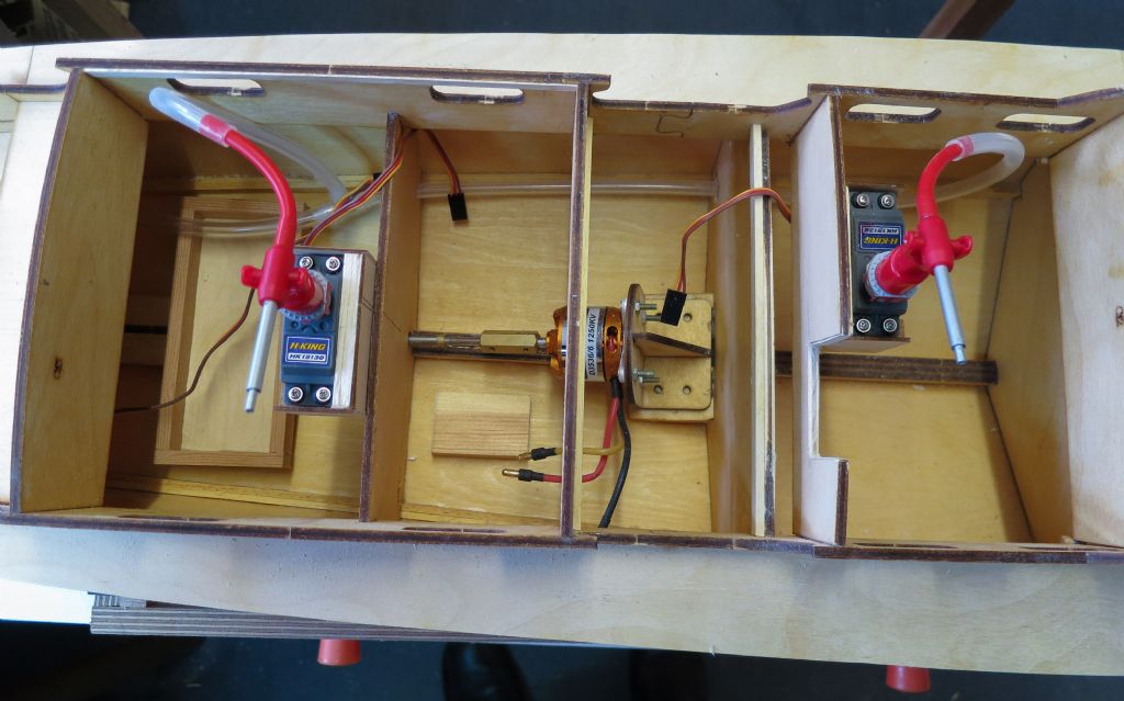
Turnigy servo speed regulator
Turnigy servo speed regulator
- This topic is empty.
Viewing 9 posts - 1 through 9 (of 9 total)
Viewing 9 posts - 1 through 9 (of 9 total)
- Please log in to reply to this topic. Registering is free and easy using the links on the menu at the top of this page.
Code of conduct | Forum Help/FAQs
Latest Replies
Viewing 25 topics - 1 through 25 (of 25 total)
-
- Topic
- Voices
- Last Post
-
- Fairey Huntsman 31 1 2 … 5 6
- 14
- 1 week, 2 days ago
Viewing 25 topics - 1 through 25 (of 25 total)
Latest Issue
Newsletter Sign-up
Latest Replies


