The world's leading magazine for all model boating interests
Shemarah II
Shemarah II
Home › Forums › Scratch build › Shemarah II
- This topic is empty.
-
AuthorPosts
-
8 January 2012 at 19:29 #32906
Gareth Jones
Participant@garethjones79649I forgot to add this bit. One of the features of the wheelhouse is that there are several free standing flat screen displays. Has anyone found a good method of simulating these with some form of internal illumination? I guess in real life these would be no more than 2 inches thick so, even taking a few liberties, the model items could only be 2-4 mm thick. Maybe there are some edge lighting LEDs that could be used – anybody know?
8 January 2012 at 20:37 #32908RJR
Participant@rjrYou could try micro LEDs thay are flat and not much more than 1mm thick I used them on a loco hereOr how about shoe lace lights that are cheap fibre opticsthey could be connected to the edge of a thick (2mm) clear plastic screen and would illuminate it I have used red ones but I think you can get white or blue12 January 2012 at 08:41 #32995Gareth Jones
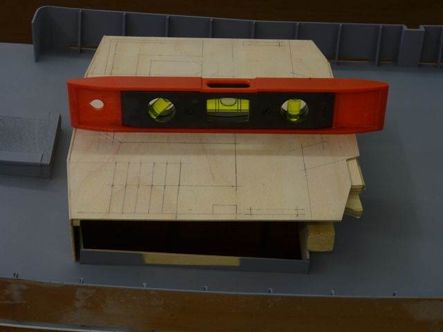
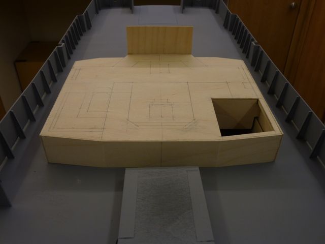
Participant@garethjones79649I have now started construction of the wheelhouse and in the process come up across a couple of confusing drawing errors. The picture below shows the wheelhouse floor with the front vertical panels to the deck already attached.The drawing has front and rear elevations of the wheel house which show the height from the deck to the wheelhouse floor to be the same front and rear. However because of the sheer on the deck the height of the panel at the back is greater than at the front. Fortunately I spotted this before cutting the parts out. I packed up the back of the floor so that it was level and parallel to the waterline and then measured the required height of the panels at the back and the tapered ones along the sides, as shown in the photo above.The picture below shows a view of the front of the wheelhouse base where a second error exists and this time I was not smart enought to spot it before building it in.The main front panel of the wheel house leans forwards and is tapered, being wider at the top because the sides also lean outwards. Unfortunately the plan view of the wheel house shows the top and bottom edges of this panel being the same length, the longer top edge length. This means that I have made the centre part of the floor, immediately behind the hatch about 10 mm too wide and the two side pieces 5 mm too narrow. I am currently pondering how to get round this but the thought of starting all over again does not appeal. Since the layout of the interior looks OK I will probably have to make the two outer windows slighly narrower than the original and the three centre windows slightly wider.Because all the upper sides of the wheelhouse slope and are tapered I have decided to cut templates from card and tape them all together before cutting and glueing the final ply parts. If there are any more confusing aspects of the drawing then this should show them up before reaching a critical stage.The Halfords grey primer has turned out a bit too dark so I have subsequently given the deck a final coat of Humbrol Grey (Matt 64), which fortunately went on without any problems. I dont like mixing different paint suppliers materials but in this case it worked OK. The next step in painting is masking off before spraying the inside of the bulwarks gloss white.13 January 2012 at 08:53 #33041Gareth Jones
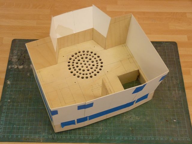
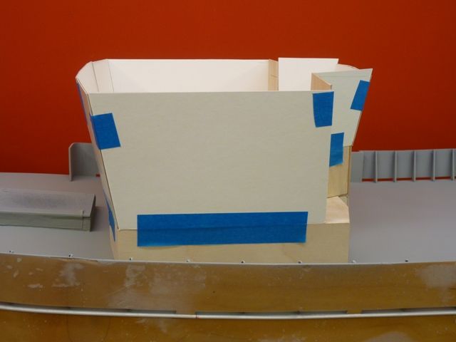
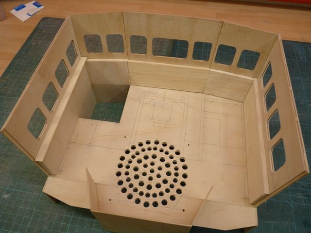
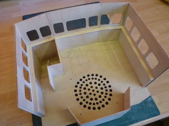
Participant@garethjones79649Here’s the cardboard cutout wheelhouse assembled on the bench. The circular pattern of holes are where the sound system speaker will sit under the floor. The rectangular hole in the corner is where the steps lead down to the main deck. Making the cardboard assembly should save a lot of trial and error with plywood sheet.I dont know how model boat designers go about creating the drawings for their plans but I guess in most cases they dont have access to detailed engineering drawings of the real thing. For an assembly like the wheelhouse, where there are few right angles or parallel lines it must be difficult to produce an accurate drawing from photographs. As a result its probably unreasonable to expect to be able to simply scale all the dimensions from the drawing. Some degree of interpretation and judgement has to be applied to get a good result. However I think that’s where the builder can gain a lot of satisfaction from saying I created that, not just I copied the drawing.I plan to laminate the sides from two outer sheets of 0.75 mm ply with a further 0.75 mm sheet of ply in the middle, cut away to allow 0.75 or 0.50 mm clear plastic sheet to be slid in from the top for the windows, stealing the principle from RJR’s Westral Chief. (thanks very much for the idea)Here’s the wheel house sitting on the deck after the deck had been reprayed a lighter shade of grey (wasn’t that the title of a Procol Harum song?)15 January 2012 at 10:06 #33109Gareth Jones
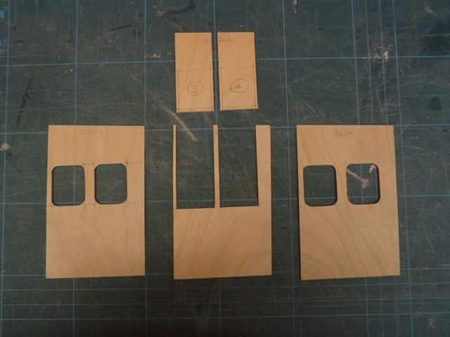
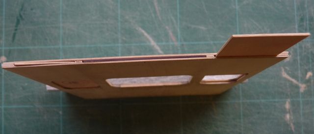
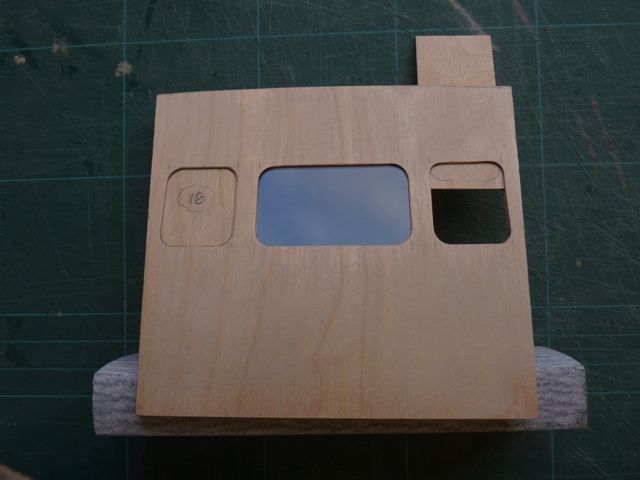
Participant@garethjones79649RJR’s idea for fitting windows worked beautifully when adapted to plywood. It’s particularly good on Shemarah because the wheelhouse windows are recessed in to the structure with no visible external frames. Here’s a picture of one of the front/side panels in its three main component parts in 0.75 mm ply. The window apertures have been cut from the front and back component and a slot 2 mm wider and deeper from the middle section.The front and back pieces were then clamped together with a couple of bulldog clips so that the window apertures could be finally trimmed to match. The middle section was then glued to the front and left to dry flat under a couple of batteries. Any surplus glue was around the edges of the slots was wiped off and then the back panel glued in place. Aliphatic resin was used to allow time to slide the panels together in the correct register. Here’s an end view of one I made earlier, showing the slots where the windows slide in. The original ply pieces cut from the centre sheet were sanded smooth and the edges also sanded and chamfered so that they can be inserted back into their original positions to mask off when painting.The picture below shows the finished effect with a trial piece of clear 0.75 mm thick PVC fitted in the centre position. It slides in easily, does not get scratched in the process and does not end up with glue marks which are impossible to remove. All the PVC window panels can be fitted after the whole wheelhouse has been finished up to roof level.Edited By Gareth Jones on 15/01/2012 10:10:30
16 January 2012 at 07:28 #33116RJR
Participant@rjrGlad to have been of help, They look good!
27 January 2012 at 08:31 #33197Gareth Jones
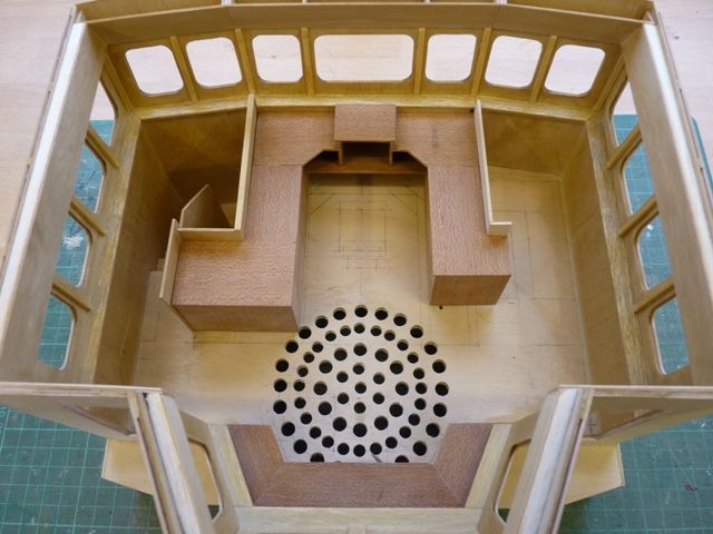
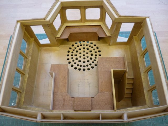
Participant@garethjones79649The wheelhouse is progressing slowly with three sides assembled and the interior beginning to take shape.The lower part of the sidewalls are thicker than the window area and there is a shelf all the way round just below the windows. The lower sides have been built up with some 3/16 balsa and will be covered in 1/32 ply. The shelf is being made from some 8 mm wide wooden strip. The sidewalls will be stained a light oak colour before varnishing. The main control consoles at the front and back are darker and will be made from some 1/16 mahogany sheet.The lower sidewalls have now been fitted and the stairwell, stairs and partition tacked in place with superglue. At the top of the stairwell the real Shemarah has a large reproduction of an old map of the world lit by a lamp with a brass shade. I am considering trying to represent that in the model as one of those little details that make the difference between a good model and one that really impresses.
27 January 2012 at 09:11 #33199Bob Abell 2
Participant@bobabell2An excellent build, Gareth
The idea for the windows qualifies for a Eureka Moment!
There’s nothing worse than carefully painted window frames…..They never look right!I like the nicely drilled holes in the floor….any misalignment and the impression is ruined!
And it’ s nice to see you working in wood too!
Bob
21 February 2012 at 19:18 #33474Gareth Jones
Participant@garethjones79649I have to confess that I have been unfaithful to Shemarah for the last few weeks as I have been having an affair with Lady Jane, a very pretty but rather time consuming plank on frame steam launch. However I decided she was not the right one for me and so she has gone back to her supplier for someone else to play with.
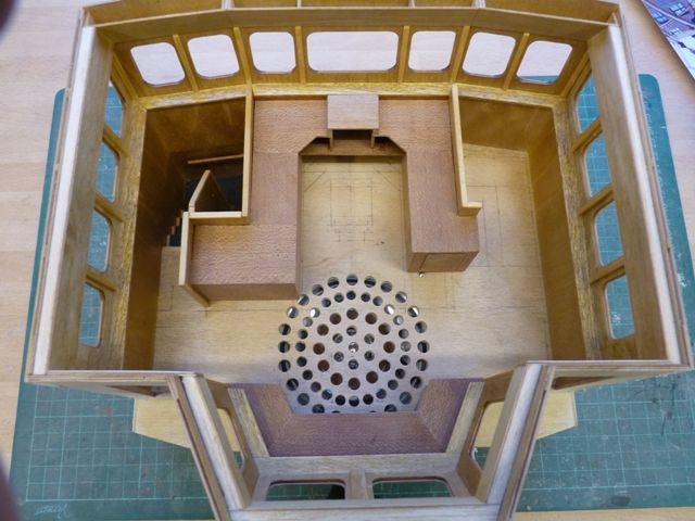
Shemarah's wheel house is coming along quite well with most of the control consoles now made from 3 mm mahogany sheet.
Now that some warmer weather has arrived I think I might make a start painting the hull as a change from woodworking (and especially planking).
29 February 2012 at 18:05 #33561Gareth Jones
Participant@garethjones79649One minor correction to the last post, the control consoles are made from 1.5 mm mahogany sheet, not 3 mm. I have added a bit more detail and fixed in the stairs, handrails and the simulated flooring in that area. I am not sure what the flooring should be like but on my narrow boat I found that black garden weed membrane looks quite convincingly like non slip flooring so I have used that again on Shemarah. It is stuck down on the floor using Scotch repositionable Spraymount adhesive. I found the best way to cut it to size was to cut an oversize piece of material and spray the back with adhesive. Lay this flat, glue side down on a sheet of clean glass. Cut out the required shape with a sharp scalpel, using a template or the appropriate measurements and then peel the membrane from the glass and fit it in place. The adhesive lets you have several attempts to get the material in the right place before it loses its tackiness.
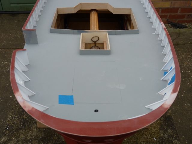
Before I could start painting the hull I needed to add the capping rail on the bulwarks. This turned out to be quite straightforward using 0.75 mm ply fixed with superglue. Around the bows I made a series of cardboard templates to shape the ply and scarfed the joints. It's a lot easier trimming the outside edge than the inside so I cut and sanded the inside edge to fit flush with the edge of the bulwark stiffners before fixing it in place. The rail was then glued in place and the outside edge sanded flush with the outer edge of the bulwarks.
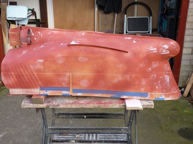
The deck area was then masked off and the majority of the hull has been sprayed with Halfords acrylic red primer with Shemarah upside down. After the first coat there were quite a few areas needing filling and sanding back smooth.
Even after the second and third coats I was still finding the odd bit needing filling but after the final 6th coat it looks OK. There is a lot of area to cover and it took two 500 ml cans to do 95% of the hull.
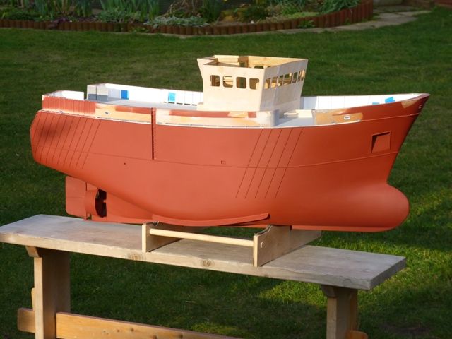
The next step is to mask off the deck again and complete the hull spraying in primer, this time with the hull the correct way up. The area above the water line then needs to be sprayed gloss red, for which I plan to used Halfords tool box red. There is a white stripe just above the waterline and a further shaped white area above that. At the moment I am not sure whether to spray these areas or use Solartrim which should give a much crisper edge. However I am not sure how waterproof and robust Solartrim will turn out to be. That job needs to wait till next week though, because Shemarah will be off to Goole this weekend to sit on the club stand at the annual Goole Hobbies exhibition. Goole MBC will be trying to retain the coveted Lord Mayors trophy for the best stand in the show which we won last year for the first time, after 18 years trying.
Edited By Gareth Jones on 29/02/2012 18:06:27
Edited By Gareth Jones on 29/02/2012 18:06:47
9 March 2012 at 20:38 #33657Gareth Jones
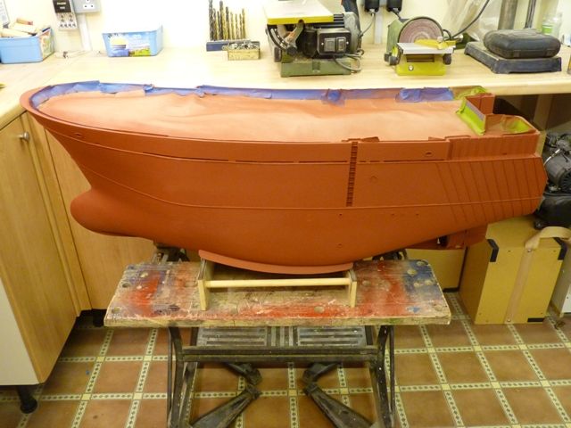
Participant@garethjones79649I have finished spraying the hull in primer and here is the final result.
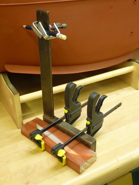
The next step was to mark the waterline using my usual method of adapting a set square as shown in the picture below. The stand holds the hull in the correct sailing attitude with a level waterline so its relatively easy to draw the line without having to mess about getting the hull at the right angle.
The hull has now been masked off and sprayed with Halfords tool box red acrylic gloss. I find that newspaper is a bit unreliable as a masking medium so I have been using some thick brown paper which we bought from B and Q where its sold as a lining paper for using under carpet underlay – its stops the rubber sticking to your floor boards. It works really well for masking and is much more robust than newspaper.The half round reinforcing bars on the sides and stern are a real pain to mask over as the tape tends to lift from the corners on each bar. Also I have found that the paint does not fill the joint along each bar very well, leaving a line along each each side of the pieces of half round plastic. These gaps didn't really show up when the hull was unpainted but once the first couple of gloss coats had been applied they looked awful. At that point I stopped painting and went back to filling. I also found that a fillet of paint applied with a fine brush along each strip made a big improvement so I have been working my way round the hull for the last few days. Another couple of coats of gloss produced a much better result and I have now left the hull to dry so I can have a good look in the daylight over the weekend. There are a couple of runs on the transom, a small area near the bow that needs rubbing down again and a few areas that are not very glossy. However I am going to spray the hull with satin varnish anyway so a few slightly matt areas is not too much of a concern. Hopefully I should get the final coats of gloss done on Sunday.
I am planning to use white Solartrim to create the waterline stripe and the white areas on the upper parts of the hull. I guess I will have the same problem with that where it crosses the reinforcing bars but at least I have had some practice with the masking tape so far.
23 March 2012 at 06:29 #33748Bob Abell 2
Participant@bobabell2Hello Gareth
What's the latest work in progress pictures etc?
Bob
24 March 2012 at 09:24 #33753Gareth Jones
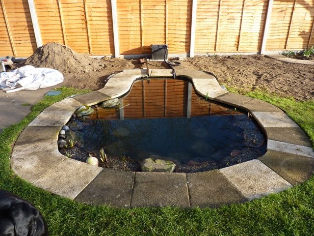
Participant@garethjones79649Sorry Bob, I have been diverted onto other springtime priority jobs for a while, namely finishing the back garden fence and digging a new and bigger pond. The liner had started to leak on the old pond and we decided to reposition the whole thing to a more suitable location, not far away and near enough to shovel some the soil straight out of the new hole into the old one. Now that its finished it also provides a bigger and more convenient test tank as well as a home for the fish.
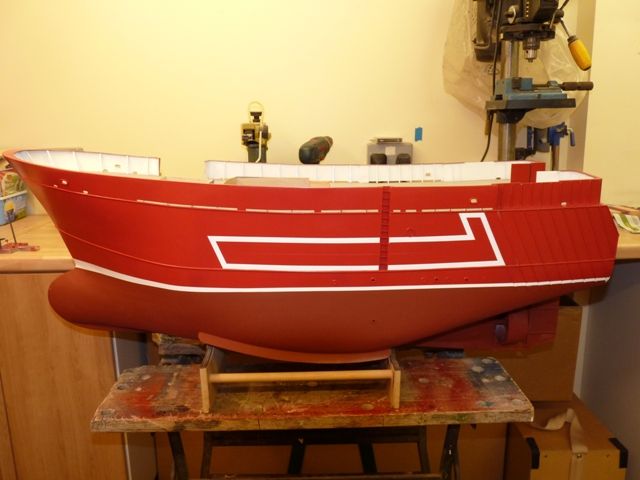
The main progress on Shemarah has been painting the hull. The top part has been masked and sprayed Halfords tool box red gloss. The white waterline stripe and the hull markings were a bit of a problem. Where the reinforcing bars cross the line its a real sod to mask off. Also in some areas of the bulwarks where there was the odd bit of overspray of red onto the white it was really difficult to touch up as the white seemed to melt into the red and just go pink.
I decided to try using white Solartrim for the waterline stripe as an alternative to painting. This gave a really crisp line but did not really look very convincing – it looked like a strip of plastic film rather than paint – not surprising really I suppose since that's what it was. I managed to peel it off by heating it with a hair dryer and apart from a few bits that had to be scraped off gently it all came off OK.
I then started again and masked the waterline stripe and the hull side markings and sprayed the stripes with Revell gloss white acrylic using an airbrush. This was my first attempt at airbrushing and I spent a while practicing and experimenting with the pressures and flow settings before I was reasonably confident. The paint was thinned with 1 part Revell acrylic thinner to 2 parts paint. This worked quite well. I think that because the coats are so thin and dry so fast it covered the red much better and did not seem to soften the lower coat of red and turn pink. It was still a bit fiddly with the airbrush and if I left too long between coats, more than about 10 minutes, the brush was clogged up with dried paint and had to be cleaned.
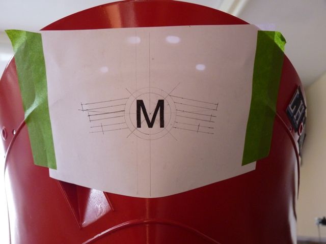
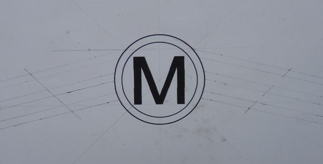
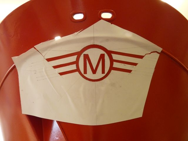
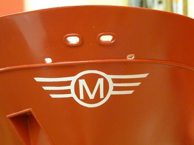
The next challenge was doing the markings on the bow which is a white M in a circle with 'wings' on. I guess the M stands for Moodie, the family which own and operate Shemarah II. Flushed with sucess from airbrushing the white stripes I decided to make a mask to spray the marking. I used a piece of inkjet vinyl paper I have had for some time but not used very much as I found my printer would not print crisply on to it and the result was always fuzzy.I first printed the letter M and drew a correctly sized circle onto a sheet of paper and taped it on the bow. Using my waterline marking method as described earlier I was able to mark the angle of the wings so that they lay parallel to the waterline.
I then printed the circle and letter M on a sheet of the vinyl and drew the wings in the required position.
I then carefully cut out the shapes using a sharp scalpel and stuck this on the bow. This was a bit tricky as the mask stuck on in the wrong places and tended to tear when I tried to reposition it. My biggest mistake was trying to use too large a sheet of vinyl as it was difficult to get it to take up the contour of the bow. I would have been much better off using a smaller sheet and then masking around the outside. However after a bit of fiddling and additional bits of masking it was stuck in the right place and could be sprayed white.
The mask was then peeled off and after a few bits of touching up with red, the final result was quite good, maybe not exhibition standard but I am quite pleased with the effect.
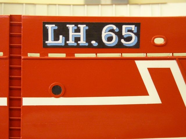
The next step is to put on the registration marks which will be done using Crafty Computer paper water slide decals. So far I have just printed off a set of paper copies to get the size of the letters right. I dont know what font was used on the real Shemarah but I have found one which looks reasonably close and should be quite convincing. Heres one of the trial markings temporarily stuck on.
25 March 2012 at 07:27 #33761Bob Abell 2
Participant@bobabell2Thank you, Gareth
When you float your boat…..There won't be much water left in your pond!…lol
I agree that a painted waterline is more authentic than plastic tape
Bob
31 March 2012 at 16:20 #33815Gareth Jones
Participant@garethjones79649I have spent the last few days making and fitting the registration letters and Shemarah lettering on the bow and stern.
The area of the bulwarks where the letters were to be applied was masked off and sprayed matt black. I had forgotten just how glossy the decals come out so I would probably have been better using gloss black.
The registration letters have been made using Crafty Computer Papers's inkjet waterslide decals. Essentially you design the graphic you wish to use on your personal computer. I usually use Print Artist which gives plenty of scope for graphics and lettering in a wide range of fonts, colours and styles. I could not find an exact replica of Shemarah's lettering but, apart from the figure 5 the rest is pretty close to the real thing. Having designed the graphic you print the image onto the special paper. There are two types of paper, a clear one for use on a light background and a white one for use on a dark background. Since you can't print white on a normal inkjet printer I used the white paper and printed the graphic with a black background. The advice is to set your printer on the normal print settings but I have found these tend to result in some smearing and blurring of the edges of the different colours. The best option I have found with my Canon printer is to set it on the colour photograph and glossy photo paper settings. Its best to print a few spares as the application process is a bit tricky, especially for larger decals which are rather fragile when being transferred from the paper to the model.
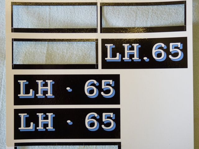
Having printed off the graphics and left then to dry for an hour or so the paper is then sprayed with a clear laquer or varnish, nothing special required. Here are a few of Shemarah's left over after the rest have been applied.
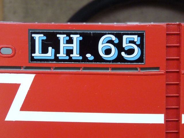
The decal is then cut from the sheet and trimmed to the correct size. I left a gap of around 1 mm all round between the edge of the black rectangle on the hull and the decal. The decal is then dipped in warm water with a drop of washing up liquid for a minute or so and then slid into position on the model. This is a bit tricky and the paint on the decal tends to crack and flake around the edges where it has been trimmed. Here is one of the decals at this stage and you can see where the ink has flaked around the trimmed edge.
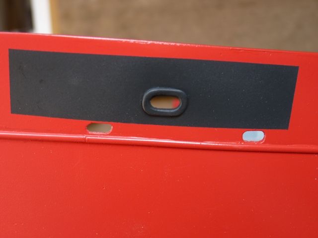
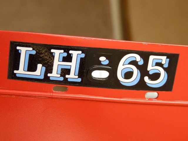
After leaving the decal to dry overnight the edges and any cracks can be touched up with the appropriate paint and subsequently varnished over. Here is one of the bow markings after touching up. Because of the opening for a mooring hawser I had to fit the front markings as three separate pieces.
The decals come out a little thicker than commercially available ones but have the big advantage you can tailor them and create pretty well exactly what you want.
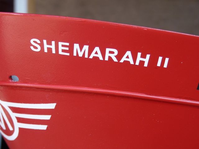
After fitting the registration letters I put the Shemarah II name on the bow and stern using BECC 8mm white letters. This turned out to be slightly trickier than those I have done in the past. Normally I print the name I wish to reproduce at the size of the letters, eg for the 5 mm ones Microsoft Word and Arial Bold font at 20 point size is a good match. For 8 mm I used 28 point size printed 115% bigger than standard. The printed name is then trimmed to a strip of paper that can be taped on the hull, directly below where you wish to fit the letters The vinyl letters are then pressed on, using the strip of paper to get a level line and correct spacing. The complication on Shemarah was that the letters were fitted on a curved area of the bow. Taping the printed letters gives a straight line if you are looking up from underneath but looks odd when looking from the side or above as it looks like the lettering sags down in the middle. I had to compensate for this by marking the hull a set distance down from the top edge and fitting the letters to these pencil marks rather than an arbitrary straight line along the piece of paper.
The finished result looks fine and the hull is now in the process of being sprayed all over with satin polyurethane varnish. In the next few days I will refit all the electrics back in the hull and Shemarah can go to sea again while work continues on the superstructure.
8 April 2012 at 19:52 #33907Gareth Jones
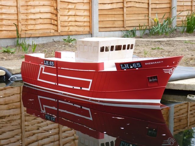
Participant@garethjones79649Shemarah is now seaworthy, or at least pondworthy again after being given three coats of satin polyurethane varnish. All the electrics in the hull have been refitted after a few modifications to the lighting circuit. There will effectively be three lighting circuits, one for the displays in the wheelhouse, one for the nav lights and one for all the floodlights and trawling lights. The default setting, if the lights master switch is on, will be for all three circuits to be on. This means if the boat is on static display at a show I can have all the lights on without needing to have a transmitter switched on. Two of the switches in an Action Electronics Quadswitch are then used to switch the nav light and flood light circuits on or off individually. Before fitting the two electrical panels I spent a day or so drawing out the final wiring diagram while I could see and remember, where all the connections are, and which wire goes where.
The model was then reballasted in the pond (without it overflowing Bob,) The total weight is now 60lb with 25 lb of removable ballast in 4 blocks, which are fitted once the hull is in the water, immediately prior to sailing. There is also 10-15lb of fixed ballast which is adjustable but not practically accessible when sailing. A trial sailing session at Goole showed this is quite a practical method of operation with the built in handle making lifting the 35 lb hull in and out of the water quite straightforward. However I am on the lookout for a suitable pram to convert, to make a trolley to move the model around on where parking near the pond is not possible.
I did come across a bit of a problem prior to taking the above photo. I have bought a suitably sized anchor for Shemarah but when I came to fit it I discover the shank would not fit up the 6 mm brass guide tube in the hull. Bit of an oversight there, should have bought the anchor and tested it before I fitted the tube. The tube has had to be removed (soldering iron poked down the hole to warm it and soften the araldite) and a 10 mm tube will need to be fitted in its place. The holes in the bow and deck have been opened out and temporarily the anchor is just held in place with a hidden bulldog clip while I get the ends of the new tube to fit.
8 April 2012 at 20:22 #33908Gareth Jones
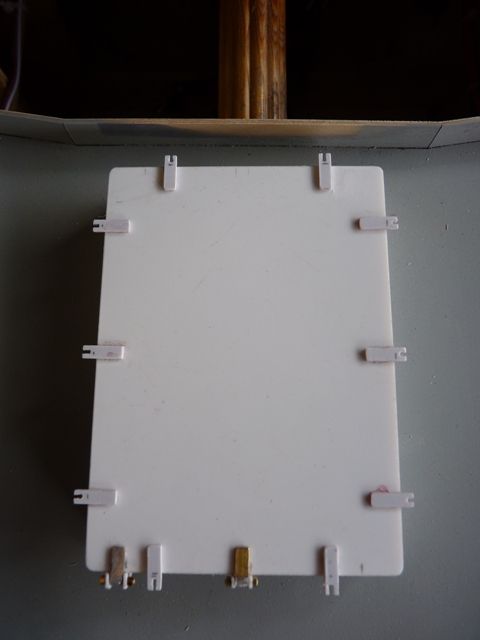
Participant@garethjones79649I have also come across another oversight as I will recount later in this posting. I decided that since Shemarah can be sailed again it would be a good idea to make and fit the hatch that covers the electrical switches and fuses just in front of the wheelhouse. In practice on the real ship, this is the hatch which is used to offload the catch when in port. I decided I would deviate from my normal custom and practice of using ply and make the hatch from 1 mm plasticard as a bit of a learning exercise.
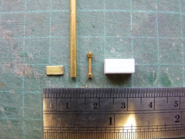
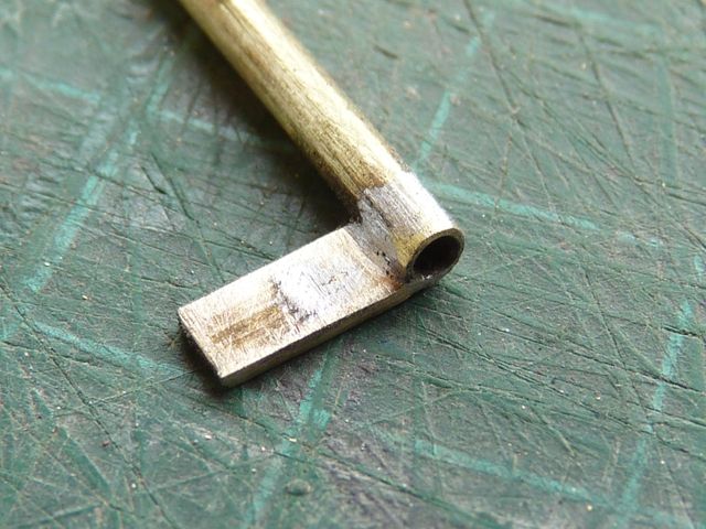
Heres the part finished hatch with the brackets for the toggle bolts fitted (but you will have to wait a week or so to see how I am going to make those). The hinges were made from 4 components, a short piece of brass strip, a length of 3/32 brass tube, a 1 mm bolt and a piece of 6 x 6 mm square section tube,
The brass strip was soldered to the tube before cutting the tube to length as this is much easier than trying to hold a 3 mm length of tubing while soldering it to the brass strip.
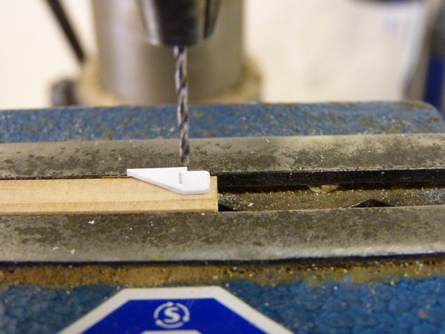
The box section plastic tube was cut away and drilled to form the part of the hinge which fixes to the hatch coaming. It was easier to drill the hole if the plastic part was fitted on to a piece of suitable thickness timber strip which allowed it to be clamped in the vice.
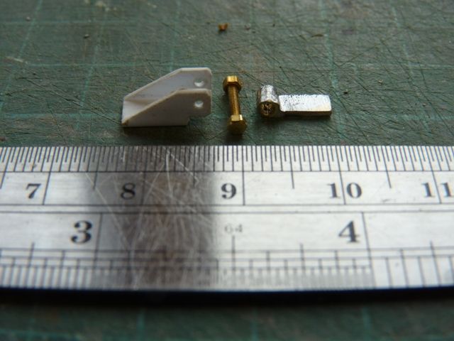
The parts were then assembled off the hatch as it was much easier to fit the nut on the bolt and crop the bolt at this stage.
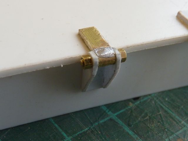
Heres a completed hinge glued on to the hatch with solvent weld for the plastic parts and thick superglue for the brass to plastic joint. As you can see the parts still need a bit of polishing and tidying up to remove the surplus solder.
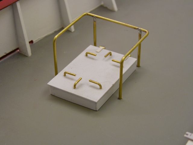
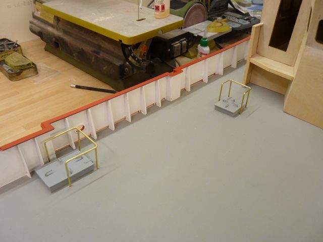
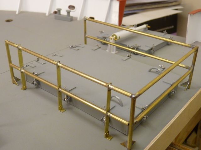
The next assembly was the hand rails around the hatch. These are fixed at the right hand side and back but the left hand side is of different construction and can be folded down on the deck to allow access to the hatch.
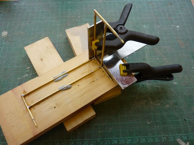
The rails were made from 3/32 brass tubing which looks about the right size, being approximately 2 1/4 inches diameter at full size. A short length of 1/16 brass wire was fitted into the bottom of each upright to act as a spigot and locate the uprights in holes in the deck. The picture below shows the railings being soldered together with metal set squares used to hold them at the correct angle and act as a heat sink and prevent the already soldered joints coming loose.
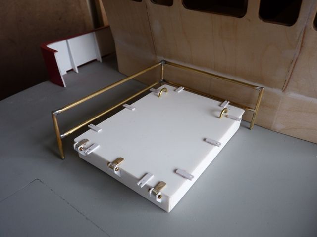
The railings were then fitted around the hatch and an error then became apparent.
The hatch is much higher, relative to the bottom rail than on the real vessel. The hatch was made to the drawing but I guess the height of the coaming was increased to protect the model from water ingress. On the model it is around 15 mm high but on the real ship I would guess around 8 inches, or 8 mm at 1:25 scale. However all is not lost, it will be reasonably straightforward to reduce the height of the plasticard hatch cover by cutting or sanding away the sides. I should be able to reduce the height of the coamings by around 5 mm so a reasonable compromise should be possible. Shemarah sits pretty high on the water so the risk of water overflowing a smaller coaming should be minimal. The soldered joints on the rails need a bit of tidying up again and then its on to the hinged rail on the left hand side and the toggle bolts on the hatch.
Edited By Gareth Jones on 08/04/2012 20:29:39
9 April 2012 at 20:16 #33919Gareth Jones
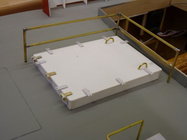
Participant@garethjones79649This morning I corrected my mistake with the height of the hatch cover and removed 5 mm from the coaming and sides of the cover. It now looks much more like the real thing.
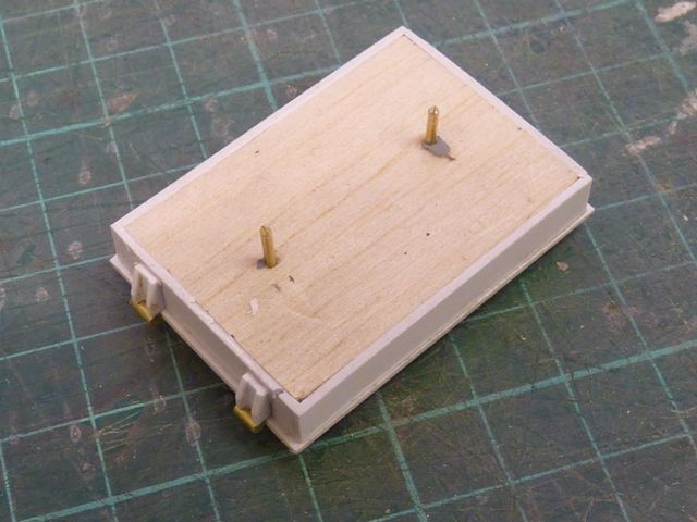
My next little project was the small hinged hatch to the left of the main one. This was constructed much the same way using 1.0 mm Plasticard but since it will just rest on the deck with no requirement for access underneath I built it around a 6 mm thick balsa core which supported the sides during assembly and holds a couple of brass pins which locate it on the deck.
The guard rails were made from 1/16"diameter brass wire soldered together and the locking handles were made from slightly thinner wire, I guess 3/64"
When I come to glue the hatch to the deck I am determined to avoid a problem I have had on my previous models. I intend to make sure there is a fillet of glue all around the deck interface so that the sides look as though they are really welded to the deck. In the past I have ended up with small gaps in this area which are difficult to fill afterwards and the component tends to look as though its just resting on the deck rather than properly attached to it.
18 April 2012 at 18:37 #34018Gareth Jones
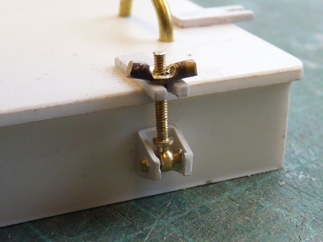
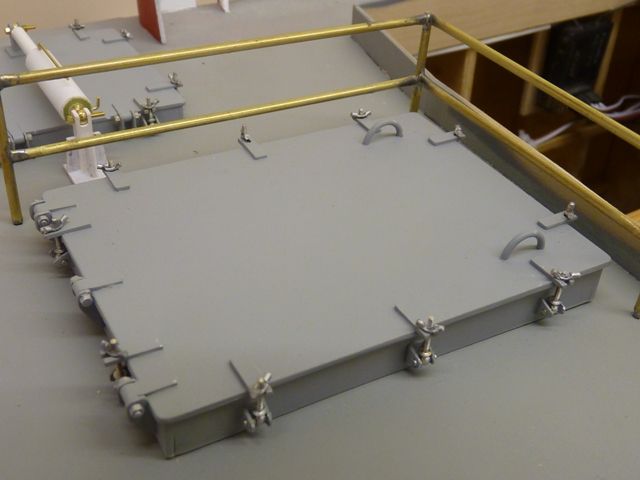
Participant@garethjones79649I have now made all the hatch toggle bolt brackets from 4 mm square styrene tubing. Its difficult to make these consistently identical by hand and I needed 18 of them. I find the best method is to make about 10 or a dozen, put them all side by side and then throw away the biggest, smallest and wonkiest and then make another batch till eventually after making about 25 I have 18 similar items.
The toggle bolts have been made from Modelling Timbers 1.2 mm eyebolts with a short length of brass rod to fix them in the brackets. The wing nuts were made from 1/16 brass rod which was softened by heating to a dull red and then punched flat. The flattened section is then softened again and then drilled to fit on the eyebolt before being cut off the length of rod. I suppose I could have gone the whole hog and tapped the wing nuts but that's getting a bit obsessive. The finished result with the wing nut secured by a smidge of superglue looks fine. The finished hatch is made up from 68 individual parts.
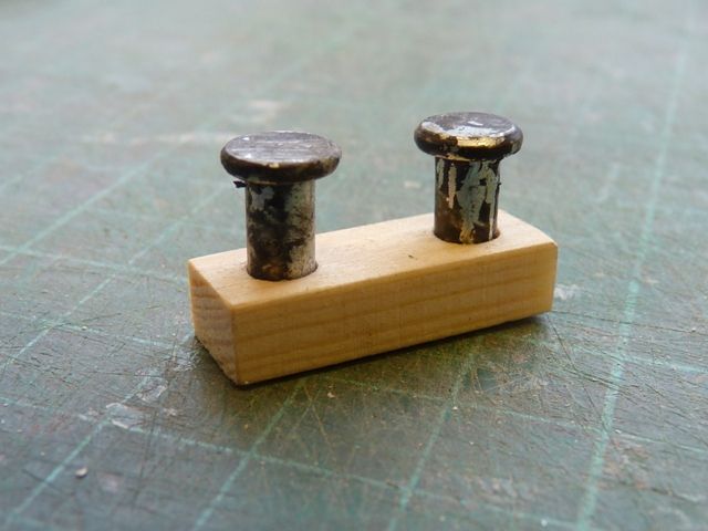
I have also made a start on the mooring bollards which are all double units, made from a short length of timber with a couple of cut down clevis pins to form the bollards. Only 7 of these to make and reasonably straight forward compared to the fiddly bits on the hatches.
Edited By Gareth Jones on 18/04/2012 18:38:44
26 April 2012 at 20:40 #34178Gareth Jones
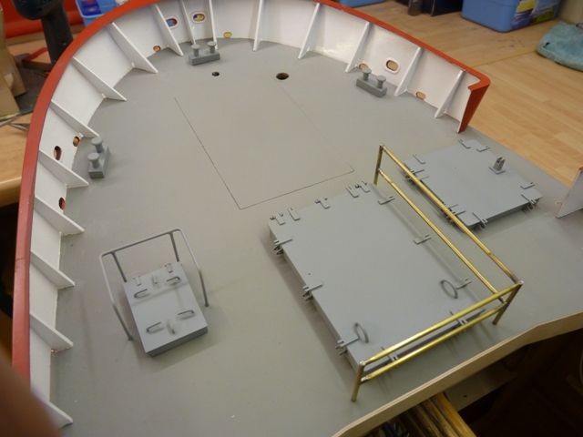
Participant@garethjones79649All the hatches have now been finished and painted. I just have about a dozen wing nuts to make and then I will be able to paint and fit the toggle bolts to the main offloading hatch and cod end hatch. They are not yet permanantly fixed in position, just held temporarily on the short brass pins that locate them on the deck. The mooring bollards have also been temporarily fitted at the front end.
The two hatches aft of the wheelhouse and their associated guard rails are also tacked in place.
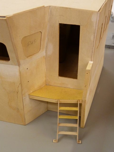
I have made a start on the wheelhouse steps and handrails. The steps are a bit fiddly and each of the treads is covered in a piece of treadplate made from an etched brass sheet. This was supplied by a company called Kit Form Services who specialise in 1:24 scale parts for trucks and miliatry vehicles. From the same source I have obtained some etched dummy nuts and bolts and some very fine windscreen wipers. The handrails on the wheel house steps are going to be pretty tricky as all the bends are at odd angles and they will have to be made by trial and error. I think I will start with a bit of soft garden wire to make a template or it could get quite expensive using 1/16" brass rod.26 April 2012 at 21:58 #34181graham mcrobert 2
Participant@grahammcrobert2Gareth can you explain what the stringers are for and its a nice looking build there
27 April 2012 at 08:07 #34182Gareth Jones
Participant@garethjones79649Hi Graham,
A good question, one that is not often asked.
When you start to assemble a plank on frame hull the frames, which run across the hull vertically, have to be fixed to a building board to hold them in the right relative position. Usually the hull is built upside down and the deck edges of the frames are fixed to the board, which provides a stiff flat reference platform. The keel joins all the frames together along their bottom centreline. However at this point the structure overall is not very stiff as the outer edges of the frame can flex and twist. Stringers usually sit in notches cut in the frames and tie the edges of the frames together to make the structure into a box which is much more rigid.
Although Shemarah is a 'plank on frame' construction it has large flat areas which are covered in ply sheets rather than long narrow planks. The stringers were positioned at points where these sheets join together so that there is a solid horizontal edge for the first sheet to attach to and be pinned or clamped while the glue dries. The next sheet can then butt up to this with the stringer bridging the joint behind.
Once all the skin is attached, whether it is sheet or planks its adds considerably to the overall strength of the struture. However if you get a sharp point load midway between two frames, perhaps because your precious model gets rammed by some idiot who is not looking where their boat is going, the skin is relatively thin and may buckle and split. The stringers reinforce the area between the frames to create a stronger skeleton to resist impact loads on the skin.
I hope that all makes sense without using too much jargon, if you have any more questions go ahead and ask, someone on here is bound to know the answer and be prepared to provide it.
Gareth
27 April 2012 at 13:30 #34186graham mcrobert 2
Participant@grahammcrobert2Thanks for the info Gareth as I have tried to build a plank on frame hull before but it kept snapping I will remember about the stringers this time
1 May 2012 at 09:37 #34234Gareth Jones
Participant@garethjones79649The main hatch has now had all the remaining toggle bolts and wing nuts added. It just needs a few paint chips and rust spots adding to give it a used appearance rather than a pristine new look.
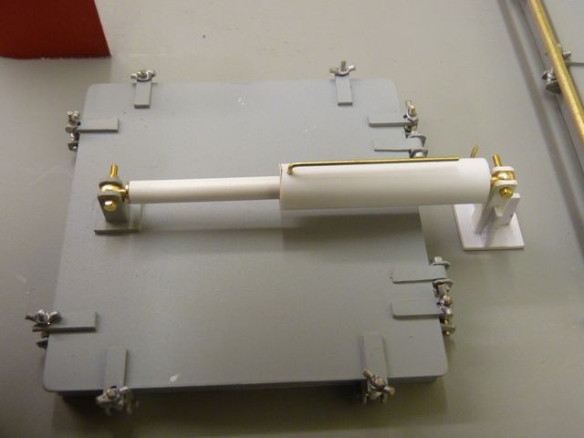
The next step was to add the hydraulic jack for the cod end hatch. This has been made from a few lengths of polystyrene tubing with Modelling Timbers tie downs for the eye ends. The pipes will be connected with some small bore black silicone rubber tubing to simulate the hoses. There is a selector valve block mounted next to the guard rails around the hatch and that will be the next but one task, after adding some supporting flanges on the bottom of the guard rails and fixing them in position.
I am tempted to keep on working on the front end of the model as I enjoy this sort of detailing work but really I should complete the roof of the wheelhouse. However that is one of the difficult bits with lots of complicated angles and curves to fashion so I suppose I have been putting it off to some extent. As long as the model is progressing, nobody can complain. Its not as though I have a fixed contract programme to meet.
Edited By Gareth Jones on 01/05/2012 10:03:02
2 May 2012 at 21:21 #34250Gareth Jones
Participant@garethjones79649Todays little task has been to add the corner gussets/brackets on the main hatch guardrail posts and then assemble and fit the fold down guard rail on the left hand side. Soldering the gussets was a fiddly job as there are two on each post at right angles to each other. Soldering the first one was quite easy but doing the second was much more awkward. Just at the point where the solder flowed, the heat dissipated into the first soldered area and the gusset flopped over. Eventually I managed to get all four corners done.
The fold down rails were more straightforward, being made from 3/32" brass tube and 1/64 x 1/8 brass strip. The final result looks quite good with some photo etched brass nuts and bolts on the hinge brackets which attach the folding guard rail to the deck. This section now needs painting before moving on to complete the hydraulic selector valve and piping to the cod end hatch actuator. After that its definitely back to working on the wheelhouse roof (perhaps).
Edited By Gareth Jones on 02/05/2012 21:23:24
-
AuthorPosts
- Please log in to reply to this topic. Registering is free and easy using the links on the menu at the top of this page.
Code of conduct | Forum Help/FAQs
Latest Replies
Home › Forums › Scratch build › Topics
-
- Topic
- Voices
- Posts
- Last Post
-
-
Aeronaut Mahogany Sheet issue
Started by:
floatmeboat2025 in: Beginners
- 3
- 4
-
2 hours, 20 minutes ago
 Colin Bishop
-
Melton & District Model Club 60th Anniversary Model Show
Started by:
Michael Campbell 2 in: Shows and Events
- 1
- 1
-
20 hours, 22 minutes ago
Michael Campbell 2
-
Fairey Huntsman 28
1
2
…
7
8
Started by:
 Chris Fellows
in: Build Blogs
- 2
- 197
-
1 day, 19 hours ago
 Colin Bishop
-
Vic Smeed’s Silver Mist
1
2
…
33
34
Started by:
Bob Abell 2 in: Scratch build
- 5
- 828
-
1 day, 22 hours ago
Tim Cooper
-
Building a hull.
Started by:
 mick east
in: Scratch build
- 7
- 16
-
3 days, 2 hours ago
 mick east
-
Fairey Faun
1
2
3
Started by:
 Chris Fellows
in: Build Blogs
- 7
- 60
-
3 days, 19 hours ago
 Ray Wood 3
-
superglue allergy
Started by:
 Alasdair Allan
in: All things floating
- 5
- 12
-
4 days, 20 hours ago
Tim Cooper
-
Model Yacht Racing – The future ??
Started by:
 Ray Wood 3
in: Sailing Models
- 4
- 4
-
5 days, 14 hours ago
 Richard Simpson
-
Vic Smeed’s Legacy
Started by:
 Colin Bishop
in: All things floating
- 6
- 15
-
5 days, 18 hours ago
 Colin Bishop
-
Eezebilt RAF Fire Boat
Started by:
Tim Cooper in: Build Blogs
- 4
- 9
-
5 days, 18 hours ago
 Colin Bishop
-
Feathered Friends
Started by:
 Chris Fellows
in: Soapbox
- 3
- 9
-
6 days, 13 hours ago
 Richard Simpson
-
4D Modelshop
Started by:
Keith Long in: Scratch build
- 6
- 9
-
1 week ago
 Colin Bishop
-
Fairey Huntsman 31
1
2
…
5
6
Started by:
 Chris Fellows
in: Build Blogs
- 14
- 139
-
1 week, 1 day ago
 Chris Fellows
-
John Cobb’s Crusader
1
2
…
7
8
Started by:
 Paul T
in: Scratch build
- 1
- 192
-
1 week, 2 days ago
 John W E
-
Complex Automata
Started by:
 Colin Bishop
in: Soapbox
- 1
- 1
-
1 week, 3 days ago
 Colin Bishop
-
RAF Fireboat ID
Started by:
 Dave Reed
in: Collectors’ corner
- 8
- 24
-
1 week, 5 days ago
Tim Cooper
-
TID steam tug 42″ – PN Thomas drawing enlarged
1
2
Started by:
 Ray Wood 3
in: Scratch build
- 8
- 33
-
1 week, 5 days ago
 Richard Simpson
-
Lady of Skye (puffer)
1
2
Started by:
 mick east
in: Build Blogs
- 9
- 43
-
1 week, 6 days ago
 Richard Simpson
-
Todays Boating
1
2
…
210
211
Started by:
 ashley needham
in: All things floating
- 84
- 5,252
-
2 weeks, 1 day ago
 Colin Bishop
-
Sea Rover Restoration
Started by:
harry smith 1 in: Collectors’ corner
- 4
- 10
-
2 weeks, 1 day ago
 Richard Simpson
-
WORKSHOP LIGHTING
Started by:
 John W E
in: All things floating
- 9
- 18
-
2 weeks, 2 days ago
 Colin Bishop
-
Mayhem Website Down
Started by:
 Colin Bishop
in: All things floating
- 4
- 10
-
2 weeks, 6 days ago
 Colin Bishop
-
MAGGIE M trawler
Started by:
 sammyk
in: Buy/Sell or Trade
- 2
- 3
-
2 weeks, 6 days ago
 sammyk
-
meter
Started by:
 Alasdair Allan
in: All things floating
- 5
- 16
-
3 weeks, 1 day ago
 Chris Fellows
-
River Queen 2”- 1’.
Started by:
Richard B in: Steam powered models
- 5
- 7
-
3 weeks, 1 day ago
Richard B
-
Aeronaut Mahogany Sheet issue
-


