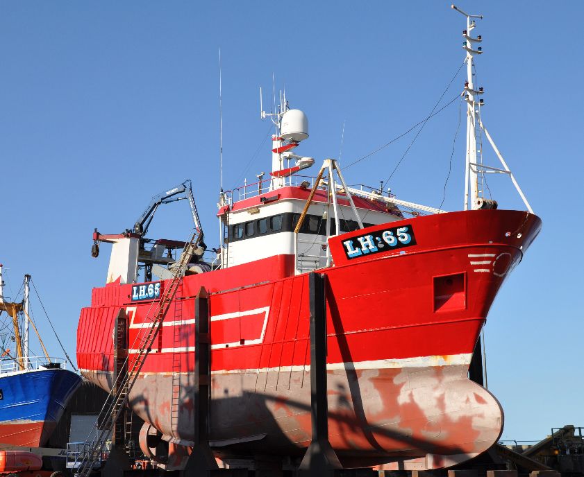
Shemarah II

Advert

Shemarah II

Home Forums Scratch build Shemarah II

  • This topic is empty.
Viewing 25 posts - 1 through 25 (of 371 total)
  • Author
    Posts
  • #29015
    Gareth Jones
    Participant
      @garethjones79649

       For the past few months I have been debating what to build next.  The choice came down to two possibilties, Shemara II (plans bought for me as a Christmas present by my wife last year) or the Spurn lightship (original builders drawings supplied by the Hull Maritime Museum).

       
      I like to work in 1:24 scale and both would be big models but they would fit in the back of my car (a Honda Jazz with magic seats!), although I will probably need a hand to lift either of them in and out.
       
      I have only built one previous plank on frame model (a TID tug) and in the end the decision was made on the basis that the Shemarah plans have all the hull sections so it will be easier to make all the frames accurately and quickly.  The plans are in 1:25 scale which will make the model approximately 1045 mm long but its very deep and wide so it will certainly be heavy when complete.
       

      I have been inspired by Paul Godfrey’s excellent built sequence of a Mountfleet Sir Launcelot, so hopefully this is the start of the Shemarah II story.  My personal target is to have the model on the Goole MBC stand at the CADMA show in 2012.  However my project manageress has just reminded me that I have a narrow boat model to finish, a porch to build, a GMBC newsletter to write and probably lots of other jobs as well so I may not meet the programme.
       
      First thoughts are that the motor will be a Graupner Speed 900BB torque driving an 80 mm 4 bladed prop via an  MFA 2.1:1 belt drive reduction gearbox. If anyone has any experience of this combination (or of building Shemara II from these plans) I would be interested to hear their views.
       
      Over the last few days I have traced all the hull frame half sections on to greaseproof paper, reversed the paper and repeated the exercise so that I have a full frame outline for each section.  I have 19 frames to cut out, the majority in 3mm ply but a couple will be in 6 mm.  These two thicker ones will be either side of the main hull opening to provide hand holds to lift the hull in and out of the water. 
       
      The centre section under the main superstructure and centre trawl winch will be removable to provide access to the inside of the hull.  Although its not a very long, its wide and deep so there should be plenty of room for the systems and the ballast.  The hull section for most of its length is around 13 inches wide and deep so I cannot cut the frames from the normal model shop pieces of 4 ft x 1ft ply sheets and will have to order some 4 ft x 2 ft from SLEC.  I made up a dummy 4 x 2 sheet from newspaper, laid it on the desk and then played around overlaying the traced frames to work out the best layout with the minimum waste.

      I have now ordered 3 sheets of 3 mm ply for the majority of the frames, 2 sheets of 1.5 mm for the skinning and 1 sheet of 6 mm for the thick frames which should give me plenty of spare stock to cover any mistakes.
       
      Not much is likely to happen for the next few weeks until Father Christmas will hopefully bring me a scroll saw and I will start cutting the frames – if he doesnt it could be a long job with my coping saw.


      Advert
      #6685
      Gareth Jones
      Participant
        @garethjones79649

        A shelter deck trawler – plans ref MAGM 2040

        #29740
        Gareth Jones
        Participant
          @garethjones79649
          Although I try not to start a new model before I have finished building the one before, I have had a bit of a Shemarah moment today. Having spent the last few days building a toilet and washbasin for my 1:12 narrow boat I decided I would do something different and start cutting out the frames for Shemarah. The tracings were laid out on the 4′ x 2′ sheets of ply and interlocked to get the maximum number of frames from each sheet.
           
          The sheet is then cut down to a size which is manageable on my scroll saw, in this case two frames, and the frame tracing stuck on with Scotch repositionable spray mount. I have found by trial and error that spraying the tracing rather than the ply means there is less glue left on the ply and its easier to sand afterwards as its not so sticky. Using repositionable adhesive makes it easy to peel off the tracing paper.
           
           
          Here are the first three frames cut out but I manged seven in total today so there are only another 12 to go.
           

          I have also spent a few hours looking for Graupner 900BB torque motors but most of the normal suppliers seem to be out of stock. Maybe I will have to risk an alternative motor which will be yet another step into the unknown.
           

          #29860
          Gareth Jones
          Participant
            @garethjones79649
            After sitting in the bath to consider the motor problem I have come up with a neat solution which looks as though it will work, but only just. I have a Graupner 900BB torque motor in my TID tug which is vastly overpowered. Consequently I plan to use that motor in Shemarah with an MFA 2.1:1 reduction belt drive to a 75 mm prop. I plan to buy a Graupner 720BB torque to refit in the TID driving its 55 mm prop directly. This has the added benefit of giving me another motor/prop combination to add to my data base (and also Colin Bishop’s). After ringing around suppliers I found 720BB torques are also in short supply but I have managed to find one and its in the post.
             
            All the frames are now cut out thanks to my daughter who decided she wanted to strip the wall paper in the dining room which gave me a bonus few hours in the workshop. The next job was to line them all up in packs of about 5 at a time and cut the slot for the keel.

            I had marked out the building board which is made from a piece of 18 mm MDF and the first frame, which is the transom was attached. At this point I realise I made a mistake in cutting the board a bit too narrow. Tightening the screws which hold the wooden frame supports to the board is a bit awkward, I should have made the whole thing a couple of inches wider.

            Too late now though I will have to carry on as is. Here are the next few frames together with the rough cut keel which is going to be a sandwich of two pieces of 3 mm ply since I have not got a big enough piece of 6 mm ply left.

            Just to give an inpression of how big and beamy this thing is going to be, here are most of the rest of the frames slotted in to their approximate position.

            The next job is to glue the keel sandwich together and then cut holes in two of the main frames for a handle, details of which will appear in a forthcoming episode. There is also quite a lot of titivating to do on the frames to tidy them up and sand them. I am not sure yet whether to have stringers in the tops of the frames at deck level. in which case I will have to cut slots for them, as I did for the keel.


            #29892
            DONALD MOODIE
            Participant
              @donaldmoodie32094
              Hi Gareth,
              My name is Donald Moodie and I am the skipper/owner of Shemarah II. I was pleasantly surprised when I came across your blog about building a model of my vessel. I am eager to follow the progress of your project and hear of any further ‘Shemarah moments!’
              Look forward to hearing from you
              Donald Moodie
              #29894
              Gareth Jones
              Participant
                @garethjones79649

                Hi Donald,.

                Its great to hear from you and I am delighted that you are planning to follow the progress of my Shemarah build. I have been considering building the model since I first saw the article in Model Boats magazine about 18 months ago. I have had a look around at quite a few model boat shows since then, to see if anyone else has built a model of Shemarah II but so far I have not seen one. I have seen some photos of a model on one of the trawler photo galleries but it looked as though it was a bit smaller than the one I am building.
                 
                The plans are very detailed so I don’t really have any excuses for getting anything wrong. However when I reach the stage of doing the wheelhouse and deck fittings, some photos of the real vessel would be very usefull. If you have any, or would be able to take some in the future I would be very grateful. Jim Pottinger’s photos in the original article will be a big help but they are pretty small and it is often difficult to understand the detail of the equipment. However I do not usually build my models very quickly so it will be at least six months before I get near that stage.
                 
                I hope you find the story interesting and the finished model does justice to the original. Having the real vessel’s skipper following the progress of the build will give me an added incentive to get on with the job,
                 
                Best wishes,
                Gareth Jones


                Edited By Gareth Jones on 19/02/2011 20:37:24

                #29898
                John W E
                Participant
                  @johnwe
                  hi there Gareth
                   
                  This looks a very nice build. I believe you are building from a James Pottinger plan?
                   
                  Some of his plans are very easy to work from. I hope you are finding this build easy.
                   
                  Looking at your build, may I please make 1-2 comments?
                   
                  It may pay you to add several stringers down each side of the hull, preferably one either side of the keel. One in the area where the bilge keels are located and one at deck level. The reason for the 3 stringers: The first stringers which are located next to the keel will give a greater area for glue, for your plank and give a stronger joint. The second one, in the area of the bilge keels will give added strength and thickness to locate the bilge keels too. Bilge keels are vulnerable and tend to be knocked / snapped off quite easily but using brass pins through the bilge keels into the stringer adds strength. The third one at deck level, gives you an area for your deck to the glued too.
                   
                  The other option I can think of, but requires far more stringers, roughly between 8-10 per side of the hull, would be to diagonally plank this hull – in 0.8 mm thick plywood, possibly covered with tissue matt and resin to give an extremely strong hull.
                   
                  Of the several hulls which I have built (plus I am busy building one of James Pottingers plans now/The Sea Lady beam trawler) I have diagonally planks 2 of them and found this method to be stronger type of build. My model of the Sea Lady I have planked longitudinally.
                   
                  Hope this helps.
                   
                  The choice is yours
                   
                  john


                  #29906
                  Gareth Jones
                  Participant
                    @garethjones79649
                    Thanks for the advice John, I am still pondering which will be the best way to plank the hull. There are some very large flat areas and my first thoughts are to cover those with 1.5 mm ply sheet. The rest I am not sure about yet but my original plan, based on a quick survey of the web, was to use 1.5 mm lime planking. Either way I will be adding a number of stringers as you suggest. I was also planning to cover the exterior with resin and glass cloth or tissue to waterproof and strengthen it. I will also coat the inside with resin. When you diagonally planked your hull with 0.8 mm ply did you use a single layer or two?
                     
                    The plans are by James Pottinger, redrawn by Dave Metcalf. They are very comprehensive and easy to follow in showing the details of the original vessel and the lines of the hull. There is no model construction information so I guess it would not be a project for a complete novice.
                     
                    I have reverted to my original profession today and done a bit of systems engineering. I have robbed the Graupner Speed 900 BB torque from my TID tug and mated it to the MFA belt drive reduction gearbox that I got for my birthday on Saturday (62 if you really need to know). This exercise was not without its problems, one expected, the other unexpected.
                     
                    The first picture below shows the motor and gearbox fitted roughly in the proposed position in the hull to get the line of the propshaft and the second is a close up of the motor.
                     

                    The gearbox instructions said mount the two bearing blocks loosely on the mounting plate and slide the output shaft through them. This proved impossible as the shaft was a hard drive fit in the inner race of the bearings. I measured the shaft and it was only about 0.001 inches bigger than a 6.0 mm drill (strange mixture of units I know but I have an imperial standard vernier calliper). The 6.0 mm drill fitted easily into the bearings so I put the output shaft in my pillar drill and polished it down with some fine wet and dry paper until it was a push fit the bearings. I then fastened the bearing blocks to the mounting plate. First unexpected problem solved.
                     
                    The expected problem was that the Graupner motor has a 6.0 mm output shaft but the pulley supplied with the gearbox is drilled 0.25 inches to suit an MFA motor. My original plan was to fit a length of 0.25 inch OD brass tube in the pulley as a sleeve and then drill it out to 6 mm ID. After three goes at this in my pillar drill I gave up – it was too difficult to align the drill and pully and I ended up drilling into the side of the tube each time. Really its a job for a lathe but I have not got one so I may eventually try and sweet-talk one of my club comrades to do the job. However as a temporary solution, which might actually be the permanent one, I tried an alternative method (i.e. bodge). I experimented with wrappping the motor output shaft in thick aluminium foil (Tesco extra thick kitchen foil) and found that a piece approximately 13 cm long gave a nice snug fit in the pully.
                     

                    To hold the foil in place as it is rolled on the shaft I first gave it a thin coat of spray mount. I then fitted the pully, tightened the grub screw and voila, a pefect fit. I then tried to fit the motor to the mounting plate and discovered the pully would not fit through the hole. Oh bugger, start again. Cut the foil, spray the foil, wrap it round the shaft, feed the shaft through the mounting plate hole and fit the motor mount screws, THEN fit the pulley. I then tested the entire assembly with the mounting plate clamped in a vice and it was fine, a bit noisier than a direct drive motor but not as noisy as a gearbox.
                     
                    The next decision to make is where to mount the motor, obviously on the end of the prop shaft you say but the photo below shows the problem area. The line of the propshaft is very shallow and gets closer to the keel the further forward it runs so the shaft has to be kept short to get the maximum clearance from the keel. However while the belt drive lets the output shaft be lower than it would be with a direct drive, the large pulley becomes the critical area. The picture below shows that either I need to change the line of the propshaft or cut away the keel and frame to get the motor lower down. The cross marked on the frame is where the line of the prop shaft should run. At this stage either is relatively straight forward and I will probably go for the latter approach when my propshaft arrives to finalise the motor longitudinal position.
                     

                    Edited By Gareth Jones on 21/02/2011 21:33:27

                    #29908
                    John W E
                    Participant
                      @johnwe
                      hi there Gareth
                       
                      I have been searching through my model books to see if I could find the plan feature – it is somewhere – I will keep looking. What I did find though was the Magazine which contains the plans for the Boston Blenheim which is the diagonally planked vessel which I used 0.8mm thickness ply for planking the outside – this isnt a James Pottinger plan.
                      The other vessel I planked was the Frederique Spashett – using lime wood for the exterior.
                       
                      You are considering using large sheets of ply to cover the side of the hull; where this is a good idea, the only downfall is ensuring that the resin doesnt crack off the exterior. So it is always well adviseable to ‘rough up’ the surface with some heavy grade sand paper. The only disadvantage of using plywood as a planking material is that when you come to cover it with epoxy/polyester the resins will not penetrate any further than the first veneer of plywood because of the bonding glue makeup to the plywood.
                       
                      The next tip I could give, unless you already know – the next time you assemble the motor gear box -stick the gear box shaft into the freezer for an hour to actually shrink the shaft and gently warm the bearings in a tin of warm oil. (NOT BOILING OIL) for approx 10 mins. This will allow the bearings to slide onto the shaft.
                       
                      Looking forward to seeing your build.
                       
                      aye
                      john
                      #29910
                      DONALD MOODIE
                      Participant
                        @donaldmoodie32094

                        Hi Gareth,

                        Hope you are getting on well with the Shemarah model, it will be no problem to help in any way I can when you need photos of inside the wheelhouse or close up deck fittings as the build progresses, please do not hesitate to contact me to help in any way I can. My email is shemarahlh@ocens.net

                        Best Regards Donald.

                        Sent from my iPad
                        Shemarah 11
                        MVRR7

                        Edited By DONALD MOODIE on 22/02/2011 19:50:06

                        #29911
                        Gareth Jones
                        Participant
                          @garethjones79649
                          Thanks very much for that John. I did try putting the shaft in the freezer but didnt warm the bearings up.
                          Also thanks very much for the offer of photos Donald, I will let you know which areas I would like in a few months time I hope.
                          Shemarah will have to take second place to our model narrowboat over the next few weeks as my wife has now finished all the soft furnishings and I am going to make a concerted effort to get it finished in time for a couple of exhibitions coming up soon. I will post some photos when it is complete.
                           
                          Gareth
                           
                          #30319
                          Gareth Jones
                          Participant
                            @garethjones79649
                            Having just about finished my narrow boat, Walbut Dream I have now been able to devote a bit more time to Shemarah again.
                            I spent a little time fettling the frames and realised attaching them to the base board with countersunk screws was not a good idea as its gives no scope for minor adjustment. Consequently I have added washers under their heads to give me a bit of scope to edge the frames backwards, forwards or sideways as required.
                             

                            I realised after my first trial installations of the motor that I would have to cut away a lot of the centre frames to get the motor low enough and close enough to the keel. I therefore decided to make two new frames with a slightly different internal profile and made them from 6 mm ply rather than 3 mm. I did try adding a 3 mm doubler to the existing frames but they tended to twist and would not lie flat after glueing.
                             

                            The prop shaft is a Raboesch sealed/self lubricating type but the large diameter end with the bearing and seal was difficult to locate accurately in the frame and just a bit too far aft for comfort. I therefore drilled a larger clearance hole in the frame and made a doubler to which the bearing housing can be glued. The doubler is bolted to the frame with clearance holes in the frame to give a bit of scope for adjustment.
                             
                            The next job was to mount the Kort nozzle which again has been done with a doubler bolted to the aft side of the frame.

                            The nozzle will be fixed and is not steerable. I will attach a section of brass strip, inset into the bottom of the keel, which will provide the bottom attachment for the nozzle and the bottom bearing for the rudder. The nozzle and propeller are both 3 inch/75 mm Prop Shop units and were delivered only a couple of days after they were ordered, pretty good if they are made to order, although being a common size maybe they were already in stock.
                             
                            The next step is to start cutting slots in the frames to take the 6 mm square stringers (or is it longerons – I am not sure – I was an aircraft engineer not a marine one) at deck level and several other locations lower down (still to be worked out) .
                             

                            #30382
                            Gareth Jones
                            Participant
                              @garethjones79649
                              I have decided where to put the slots for the stringers and spent the last few days cutting them in the frames. This morning i made the final adjustments to the location of the frames to get them lined up. I then spent an anxious hour or so trying to work out if there was anything else I should have done before I start gluing in the keel and stringers. Hopefully not as the first few are now in place starting with the shelter deck level and tomorrow I should get the rest in place.
                               

                              #30399
                              Gareth Jones
                              Participant
                                @garethjones79649
                                No skiving today to watch the royal wedding, its been a Shemarah day from morning till night. Most of the stringers are now in place, with just one left to do at mid height either side of the bow. The front ones are 6 mm x 3 mm to give a bit more flexibility on the curvy section of the hull.
                                 

                                Most of the bow has now been built up with diaphragms in the bulbous section and the upper part.
                                 

                                Just a few more diaphragms to add between the horizontal pieces which make up the shape of the bow. When you look at the full size vessel it has quite a tubby, pugnacious look about it but now with all the curvy frames and stringers on view its quite a sexy shape underneath.
                                 
                                I plan to build up the bow section with balsa before planking it. The spaces between the most forward five frames will be filled with polystyrene foam for emergency buoyancy. However I need to decide if I am going to fit a working anchor winch, in which case I will have to allow space for the mechanism and chain. I have a busy day tomorrow so not much more will be done till Sunday.
                                #30420
                                Gareth Jones
                                Participant
                                  @garethjones79649
                                  I have now completed the stringers and added the diaphragms to make up the shape of the bow to which the planking can be attached. The model now requires some serious sanding to chamfer the edges of all the curved frames so there is the maximum area on which to bond the skin.
                                   

                                  However sanding did not appeal to me today so I have installed the battery mount and motor mount while there is still reasonable access from the sides and bottom. A thin wooden strip was clamped to the side of frame 7 to locate the first battery floor bearing strip. A strip of 10 mm square timber was then glued and clamped to the frame to form the front support.
                                   

                                  This was repeated on frame 6 and the battery mount floor was cut from a piece of 6 mm ply. The floor will be attached to the supports using brass woodscrews to allow access underneath if any repairs are required at a later date. In any event the floor will need to be removed when the inside of the hull is varnished or coated with resin.
                                   
                                  A couple of pieces of 6 mm square timber were glued to the floor to locate the battery laterally. However a few minutes later, after taking the pictures I decided to remove the lateral restraints as I might need to slide the battery sideways, offset from the centreline to help correct any list in the model when it is complete. I remember when I built my first model, a TID tug, I was surprised how sensitive it was in roll, when I came to ballast it. I guess its not just the disposition of the internal components and their weight but also the shape of the hull and any discrepancies between the two sides. Being able to move the battery sideways and to a degree fore and aft gives me some scope for final adjustments.
                                   
                                   
                                  The next job was to install the motor mount and this needs a bit of carefull planning to get it in the right place. I attached the motor and gearbox to the prop shaft using a standard universal coupling and then hung the motor from the keel using a cable tie I adjusted the cable tie to get what I judged to be the best alignment of motor and propshaft, using a steel rule as a guide. All this is done with the model upside down on the building board.


                                  #30424
                                  Gareth Jones
                                  Participant
                                    @garethjones79649
                                    After a short break for Sunday tea here is the rest of todays progress. My eyesight is not very good. With my glasses on I can see from about 2 feet to infinity and with my glasses off I can see from about 4 inches to 8 inches. In between it gets a bit hazy. However the ruler helped me line up the prop shaft and motor to the best of my judgement..
                                     

                                    I measured from the baseboard to the motor mount at the front and back, both sides and took an average at each end. Having allowed for the thickness of the 6 mm floor and the 10 mm supports I marked lines across the frames where the supports would be glued on. I tried to set the mount about 1 mm too low. If its too low you can easily pack up the mount using shims or washers but if its too high you are pretty well stuffed and have to start again. Using a horizontal piece of wood as a guide, the same way as for the battery mount, I attached the suports for the floor.
                                     

                                    I then fitted the floor which has to be in two pieces because the gearbox layshaft runs through the middle. The two floor panels are each attached to the support beams using four countersunk screws and fit closely between the frames which means they can be removed and refitted repeatably in the same position.
                                     

                                    I refitted the motor and lined it up again, now with the metal mount sitting on the floor panels. I drew through the four mounting holes with a sharp pencil to mark where the mounting studs should pass through the floor. I then drilled these four holes, slightly undersize, and fitted 2 countersunk screws in each side to give me four studs on which the motor mount will sit. These will eventually be glued in to prevent them turning when the nuts are removed some time in the future when the threads may be dirty and rusty. Then I drilled out the holes in the motor mount, slightly oversize to give a bit of final adjustment. The whole lot was then refitted and I found I just needed a washer under each of the front studs to give the best lineup of the motor and propshaft. It might need a bit of tweaking when it comes to the final assembly but its fine now, the motor is easily accessible and removable.
                                    The outer part of each mount floor panel will be fitted with another stud in the centre and used to retain the ballast plates to the floor. These will be cut from a roll of lead flashing which I have stashed away under the bench in my workshop, having been left over from a long finished porch built on the front of out house about 20 years ago. I knew it would come in useful one day.
                                     
                                    #30605
                                    Gareth Jones
                                    Participant
                                      @garethjones79649
                                      The last couple of days have resulted in a bit more progress and a few minor setbacks. I have made up and installed the ladders which are set into the side of the hull. The rungs are 3/64 brass rod and the sides and back are 3 mm ply. When I did the first one I glued the two sides to the back before drilling the holes for the rungs. This did not work out very well as the drill tends to wander and the holes are neatly in a line on one side but not the other. For the second attempt I clamped both sides together before drilling them, then glued them on to the back with a few rungs in place to make sure the sides lined up – this worked out much better..
                                       

                                      The second mistake was to glue the assembled ladder to the side of the frame above the deck line (the stringer in the above picture). This bit of the frame will need to be cut off and discarded when the hull is removed from the building jig. Hopefully the top of the ladder will come unstuck without too much damage.
                                       
                                      The next job was to start sheeting the hull. I have been making up cardboard templates for the large relatively flat areas which will be covered in 1.5 mm ply. All the edges of each piece end in the middle of a frame or stringer or up against the keel.
                                       
                                       
                                      The first two pieces of ply sheet were pinned to the hull sides using 10 mm brass pins, pushed in about half way so they can be extracted afterwards. They have now been glued using aliphatic resin, as was the rest of the hull structure. I am working symmetrically gluing matching pieces on each side of the hull to balance the loads as it all dries out and hopefully does not distort.
                                       

                                      The triangular shaped area needs to be cut away from the frame and stringer as the top of the transom slopes forward. Exactly how much was a bit of a guess as the side elevation of the lines drawing and arrangement drawing did not match. The next few days will be spent progressively adding the rest of the ply sheets and then moving on to the individual 1.5 mm lime planks for the more tightly curved areas.


                                      #30647
                                      Gareth Jones
                                      Participant
                                        @garethjones79649
                                        Here’s the next area being sheeted under the aft end, plently of clamps and a few pins holding it in place till the glue dries.
                                         
                                        The next step is what I think of as one of the key steps in building a hull, where the propshaft is finally glued in position. It has to be done at this stage as the next area to be sheeted will restrict access to it. This is the first time I have used a Roboesch maintenance free sealed and ballraced propshaft and I did not find the instructions all that clear. The picture below shows the forward end where the bearing and seal housing sits. As supplied this is free to float on the shaft giving about 10 mm tolerance on the overall length of the tube. It has to be glued to the tube on or before installation to seal the prop shaft. However once glued, in this installation, there is no way of moving the propshaft assembly in or out of the model by more than an inch or so..
                                         

                                        I fitted the propeller and Kort nozzle and determined the correct axial position for the shaft and then glued the bearing housing to the outer tube using Araldite. The bearing housing is a close fit to the tube so not much glue is needed and the whole assembly stays in line. I then rotated the tube to ensure the glue sealed the whole perifery before leaving it to dry. When it was set I could then slide the assembly about an inch aft to put some glue on the outer part of the bearing housing which sits in the locating plate shown above, and at the stern where the tube enters the hull before sliding it back in and rotating it a few times to make sure the glue made a good seal with the hull. When the Araldite had set, I have to say the shaft does not feel as free as the type I am used to with brass or bronze bushes. This has a Delrin plastic bearing at the aft end and a ball race and seal at the forward end so maybe it should feel slightly stiffer or maybe more viscous would be a better description. However it rotates smoothly with no rough spots so hopefully its OK and with a bit of water in it to lubricate the bush and seal, it should free up a bit. Time will tell but it will be a real ****** of a job if it ever has to come out.


                                        Edited By Gareth Jones on 15/05/2011 21:52:12

                                        #30723
                                        Gareth Jones
                                        Participant
                                          @garethjones79649
                                          The two largest areas of ply sheet are on the sides of the hull whre there is a large flat area. I found it easier to make up the cardboard template in two pieces and tape them together before cutting out the ply sheet.
                                           

                                          I have attached this to the frames but left a gap of about 30 mm between the top of the sheet and the stringer which is at deck level. My theory is that this will enable me to cut off the surplus top of each frame easily when the hull is removed from the building board, but leave a reasonable area of the hull framework to attach the top part of the skin which will extend to the top of the bulwarks. I have had to add an additional stringer at this level but because it was difficult to slot the frames to insert it. I have just used short lengths of 6 mm square stripwood between each frame. A Colin Bishop has said in another area of the forum, B and Q now have quite a good selection of pine strips in small cross sections which are good quality and much cheaper than most model shop prices.
                                           

                                          The next step has been to start planking ‘properly’ i.e. with planks rather than sheets of ply. I am using lime strips 1.5 mm thick and in various widths of 10, 8 and 6 mm. I have started on the back end working in several areas at once, adding planks on alternate sides to allow the glue to dry and even out the stresses on the hull. I have a bit of an assortment of pins to hold the planks while gluing. However I decided to buy some more andd chose Amati 10 mm long fine brass pins which are only 0.5 mm thick. These have proved to be a bit too thin and sometime buckle when they are being pressed into a particularly tough bit of the ply frame. It is really annoying when the pin pusher slips off sideways at this point as you are pressing hard and then snaps the plank you are trying to fix into place. This usually happens right at the end when you have glue everywhere and have already attached it to about 10 frames – a good example of sods law I guess.

                                          #30957
                                          Gareth Jones
                                          Participant
                                            @garethjones79649
                                            Planking has continued with some slightly thicker pins which have proved more reliable. It is quite challenging to try and fit the planks in the best line where they will lie straightest. Provided that the planks are only bent in one plane, the edges stay straight and the next plank will butt up against it neatly. However if a plank is twisted as many inevitably are, the next plank has to be pulled or pushed sideways over part of its length to stay up against the first. I have mainly been using 8 mm wide planks and usually after three or four twisted planks it is necessary to insert a ‘stealer’ i.e. a plank which does not have parallel sides, in order to get the next plank edge to lie reasonably straight. It is impossible to plank the full length of the hull in continuous planks so I also had to try and work out the best places to start and finish groups of planks. All in all quite challenging but somehow satisfying. How well it will all look when its finished is a bit of a guess at present. Hopefully I won’t sand through the full thickness of any planks when it comes to rubbing the whole thing down.
                                             

                                            Lots of clamps of all shapes and sizes were used. As the gap between planks gets smaller it becomes more difficult to fit the clamps in place. The brass pins hold the planks in place laterally but its often necessary to try and fit a g clamp or bulldog clip to hold adjacent planks level between the frames.
                                             

                                            I had a go with a couple of ply planks at the front, which were 15 mm wide but it was very difficult to get the parallel edges to meet so I gave that up and went back to lime planks.
                                             
                                            To try and get the right profile at the bow I decided to fill the volume with balsa and then sand it down to the right profile. I included a couple of additional horizontal ply diaphragms to make it easier to hold the profile as it was sanded.


                                            I plan to cover the bow in two layers of 0.75 mm ply and heres a picture of my first attempt at making a template.
                                             

                                            The back end is now finished and looks pretty neat, a shame to cover it all in fibreglass really.
                                             
                                             
                                            Heres the final state with just the bow and the bulwarks area to skin over.


                                            The next few pictures show the hull after removal from the building board at last. Its much lighter to move around now,


                                            A look inside gives a good impression now of how much space there is and where the working systems and ballast will be able to be fitted. To my relief there were no big gaps visible between the planks and very little glue dribbled through to the inside. I wonder where it all went?

                                            I have spent an hour or so sanding down the hull but I then decided to fit the motor and Kort nozzle so the hull could go on display at the Goole MBC open day on 5th June and at the CADMA show the following weekend. As a bit of a change I have decided to start on the rudder next so I will be putting away the woodworking tools and getting my blowtorch out soon.


                                            #30958
                                            John W E
                                            Participant
                                              @johnwe
                                              hi Gareth
                                               
                                              I have to say that hull looks really impressive – and nice planking job. I am just wonder have you taken the hull off the building board a little prematurely though? I myself find that leaving the hull on the building board until I have finished filling the planks with car body filler and then sanding smooth to fill any gaps/small indentations in and also fibre glassing the hull is much easier on the building board. It gives you a stable base to work on as it prevents the hull from moving about when you are working air bubbles out of the resin either by rolling or stapling. Also, when you come to finish off the fibre glass by sanding and polishing the board will hold it steady then too.
                                               
                                              It looks a really impressive build mate…look forward to seeing how you progress.
                                               
                                              I would myself leave the rudders/motor assembly until you have finished the hull and then there is no fear of covering them with fibre glass/debris/resin etc. by accident.
                                               
                                              aye John
                                              #30961
                                              Gareth Jones
                                              Participant
                                                @garethjones79649
                                                Hi John,
                                                 
                                                Thanks for that advice. I am planning to leave the extensions on four of the frames, one at each end and two either side of the middle section, so that I can re-attach the hull to the board when it comes to rubbing down and fibreglassing the hull. However I wanted to remove most of them at this stage so that I can build up the side skins to the top of the bulwark level without worrying about how I would be able cut off all the frames at deck level afterwards, when they would be butting up against the bulwarks. I am going to cut partially through the outer area of the 4 remaining frames so they can be removed more easily at the end with the bulwarks in place
                                                 
                                                The motor and Kort nozzle were only fitted for show at the weekend to give people an idea how they look. Similarly the rudder will not be installed permanantly at this stage, just fabricated as an assembly and trial fitted.
                                                 
                                                I am planning to fill and smooth the hull with Isopon before fibre-glassing. I did toy with the idea of fibre-glassing first as I thought it might bond better to the bare wood than filler but I have subsequently changed my mind. What’s your expert opinion? I have never done this before.
                                                 
                                                One idea that did work quite well at the weekend was the built in provision for a carrying handle (see photo below). It was quite easy to carry around but the hull only weighs 5.4kg at the moment, it will be a bit different when its finished and weighs about 20 kg. Still, I think it will be more manageable than trying to get my arms around the hull and carry it that way.


                                                #31000
                                                John W E
                                                Participant
                                                  @johnwe
                                                  hi ya there
                                                   
                                                  Gareth, personally with you using a plywood along with the rest of the planking – the first thing I would do is to rough up the plywood to allow you to get a good bond to it. ~Then give the hull one coat of resin and hardener mix – allow this to soak into all the planking and you will find this will stiffen the planking up and aid you with further preparation of sanding and filling with car body filler. When you are happy with the profile, then you could fibre glass the hull – personally I would use tissue matt on the exterior along with three coats of resin with hardener mixed, allowing each coat of resin to go off before the next coating of resin is applied.
                                                   
                                                  Apply the tissue matt on your 2nd coating of resin.
                                                   
                                                  Leave it for a day or two to harden and then sand and finish to your heart’s content 
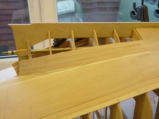
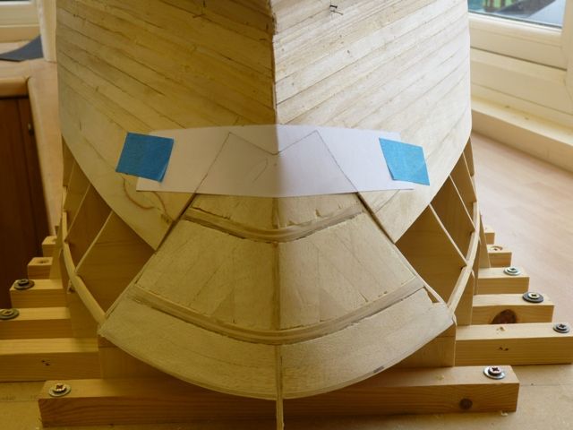
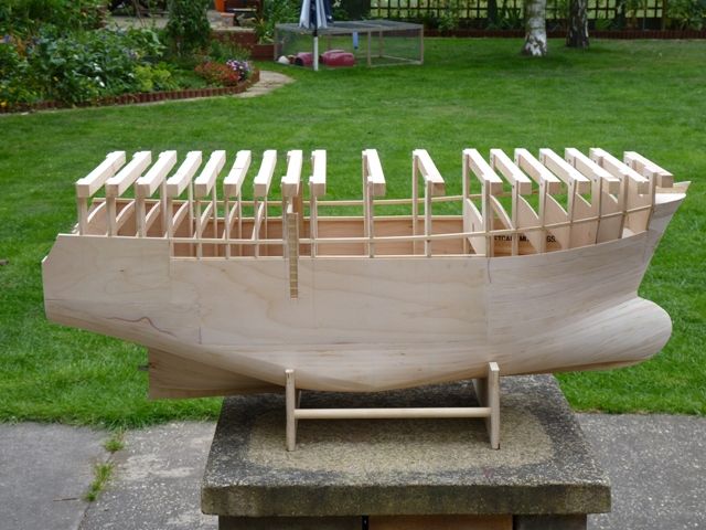
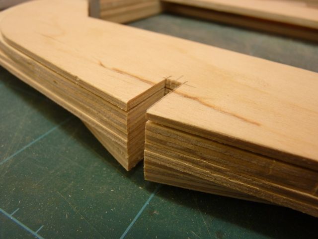
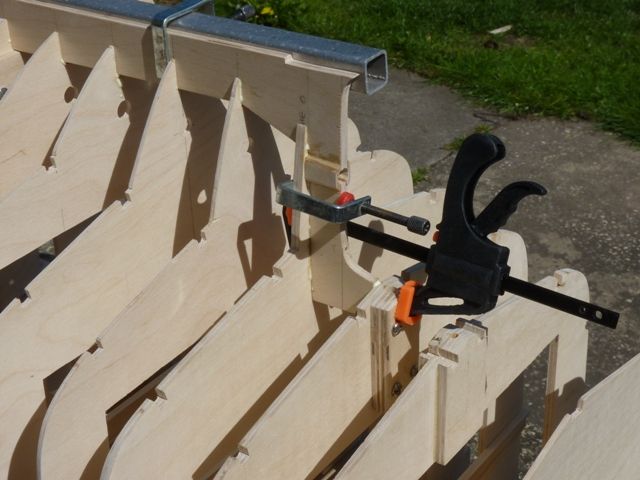
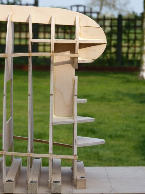
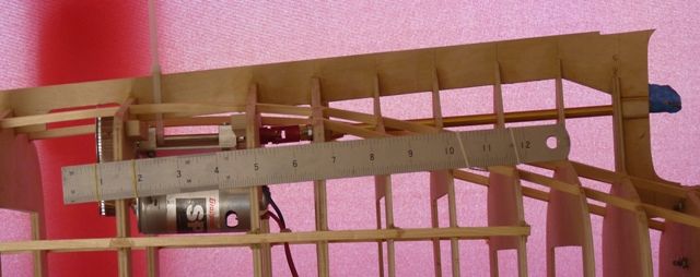
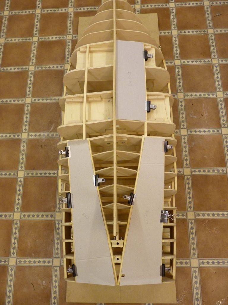
as long as you dont rub all the way back to the planking.
                                                   
                                                  I have used this method many a time on many of my planked hulls and its never let me down yet – ooooops fatal words I have just typed.
                                                   
                                                  aye
                                                  john

                                                  Edited By bluebird on 11/06/2011 21:49:11

                                                  Edited By bluebird on 11/06/2011 21:51:39

                                                  #31019
                                                  Gareth Jones
                                                  Participant
                                                    @garethjones79649
                                                    Thanks for that John. I think I will try it that way. The only possible variation at the moment is that I have a suitably sized piece of woven glass cloth which I bought years ago to cover an aircraft wing. I might try draping that over the hull to see how it follows the shapes and use that in place of tissue if it seems OK,
                                                     
                                                    Shemarah had a few days out this weekend on the Goole MBC stand at the CADMA show. It attracted a lot of interest, so much so that on the second day it was moved to the corner of the stand so it was more accessible to the visitors. If I had a pound for every person that fondled its bulbous bow and bottom I would be a rich man now,


                                                    #31031
                                                    John W E
                                                    Participant
                                                      @johnwe
                                                      hi ya there Gareth
                                                       
                                                      May I give a word of caution when using woven glasscloth. A friend in Australia used this on a diagonally planked hull which had been planked with plywood and it began to delaminate – so – my advice to you, if you are going to use this – do a test on a bit of plywood first of all and make sure that it wont peel off after you have sanded it. Also, with you sanding and finishing, if you havent sealed the fibres in the cloth properly with resin – water may penetrate and a capillary action may take place. So just a word of caution – you may be lucky and have no problems – I hope you are. Keep on building.
                                                       
                                                      aye
                                                      john
                                                       
                                                    Viewing 25 posts - 1 through 25 (of 371 total)
                                                    • Please log in to reply to this topic. Registering is free and easy using the links on the menu at the top of this page.

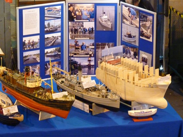
                                                    Code of conduct | Forum Help/FAQs

                                                    Advert

                                                    Latest Replies

                                                    Home Forums Scratch build Topics

                                                    Viewing 25 topics - 1 through 25 (of 25 total)
                                                    Viewing 25 topics - 1 through 25 (of 25 total)

                                                    View full reply list.

                                                    Advert

                                                    Newsletter Sign-up