How to design a new model.

Advert

How to design a new model.

Home Forums Beginners How to design a new model.

  • This topic is empty.
Viewing 25 posts - 26 through 50 (of 55 total)
  • Author
    Posts
  • #47937
    Paul T
    Participant
      @pault84577

      Dear All

      Whilst Andy goes off and starts drawing it might be a good time to explain how this particular drawing system works.

      I should stress that this is my own simplified version of Third Angle Orthographic Projection and that other variations of the same system are available.  

      Start at the beginning and get the drawing tools that you will need:

      Right angled triangle, flexible (bendy) ruler, drafting compass, pencil and eraser….all of these can be found in a school students basic drawing kit so you don't need to spend massive amounts on expensive equipment.

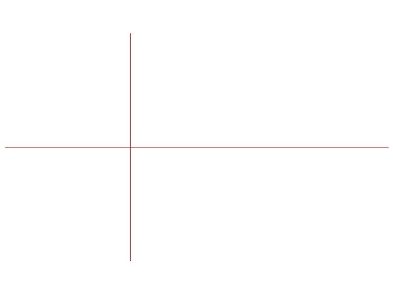
      The next step is to draw 2 lines on a piece of paper, the posh term for these line are the X and Y axis but I never bother with this as it sounds to much like algebra. Its far easier to think of them as the Up & Down line and the Side to Side line 
      3rd angle 1.jpg

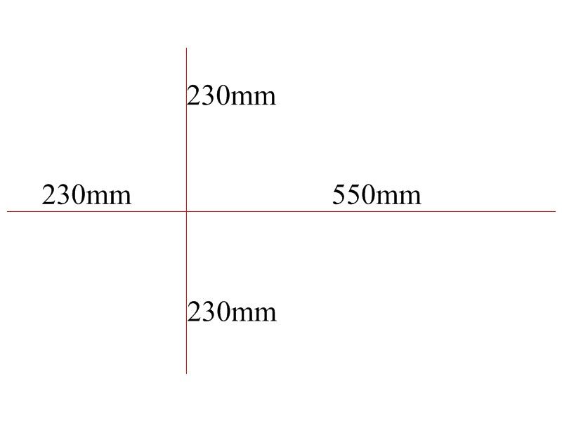
      The lines do need to be at right angles to each other and as we know the rough sizes of Andy's model we can set the length of each line. The measurements are taken from where the two line cross.

      These are called Base Lines and everything on the drawings will be set out from these lines….it sounds far more complicated than it actually is so please bear with me
      3rd angle 2.jpg

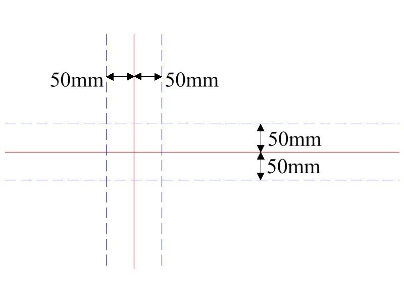
      To make the drawings less cluttered and easier to understand I always add some construction lines, you will see what I mean about being cluttered as we progress. I usually place these lines 50mm away from the Base Lines.
      3rd angle 3.jpg

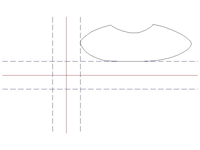
      We can now start to draw by copying our outline drawing of the side view onto the sheet. It is important to draw this image butted up to the construction lines (as can be seen on the image below). This first drawing gives us the critical dimensions from which we can build up the rest of the details.
      3rd angle 4.jpg

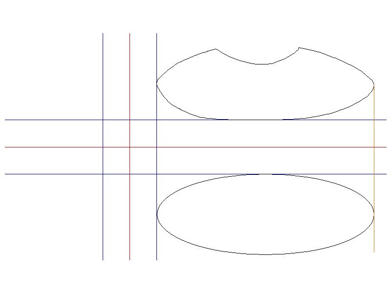
      By adding a single temporary vertical line we can transfer the overall length of the model to the lower section of the grid. With this dimension we can start to detail the overhead or plan view.
      3rd angle 5.jpg

      So far with only using a few simple right angled lines we have managed to start both the side elevation and plan drawings.

      More tomorrow.

      Paul


      Edited By Paul T on 31/03/2014 16:14:28

      Advert
      #47946
      Paul T
      Participant
        @pault84577

        This is the point where things start to get a little more complicated as we have to begin incorporating actual material sizes within our drawings.

        As everybody has their own favourite materials and method of working it would be unfair to second guess what Andy will choose to use or to try and predict how he will approach the detailing.

        However for the purposes of this exercise and to explain the process I will follow my usual methods with the following basic specifications.

        Frames, stringers and keel from 3mm birch ply, Frames at 57mm centres, Stringers at mid height on either side, Interlocking keel, Skin 1mm aircraft grade birch ply. Solid nose.

        Model access through the cockpit base, Single 300 size motor driving a single concealed propeller.

        Paul

        #47947
        ashley needham
        Participant
          @ashleyneedham69188

          Paul. I can see how you are progressing.

          In this instance, might the use of thicker balsa strips be more appropriate for the skin, simply in order to be able to blend the skin curves together a bit more (ie you can do a bit more sanding and not break through. This would also enable a nice smooth surface to be obtained using Eze-cote and glass cloth.

          I see from your initial drawing you intend a solid nose??

          It would in fact be fairly simple to get a good seal in the body-dome department if using the EMA acrylic tube, as this stuff is very stiff and a greased neoprene "gasket" could be used (closed cell rubber foam, obtainable in strip form).

          Ashley

          #47968
          Paul T
          Participant
            @pault84577

            Ashley

            In some respects balsa is a perfect substitute for the 1mm ply, the reasoning behind my choice is the extra strength that the ply provides (you cant poke your finger through the ply) I always try to build as much strength into my designs as possible so that when built they can withstand some rough handling.

            Paul

            #47969
            Dave Milbourn
            Participant
              @davemilbourn48782

              Paul
              I'm in the process of building a 30" long Boothbay Lobster Boat from the Midwest kit. The hull skin is 3/32" balsa sheet, about which I initially had an unhealthy dose of scepticism. However the instructions then call for the application of TWO layers of lightweight glass cloth and epoxy resin. After this – which is a surprisingly easy process if you thin the resin out with isopropanol – the balsa is very resistant to poking fingers. I have to say that I'm impressed, and I reckon I can get a really beautiful finish on well-sanded epoxy laminating resin with the usual Halfords rattle-cans.
              Don't lose sight of the fact that this weird little model which you and Andy are designing is only 20" long i.e. it's not one of your usual petrol-powered two-storey brick outhouses.
              Dave M

              #47972
              Paul T
              Participant
                @pault84577

                Having established the basic specifications we can proceed to work up the detailed drawings.

                As the only access is via the cockpit we have to give some thought as to how the frames are set out especially as we don't want any obstructions in this critical area.

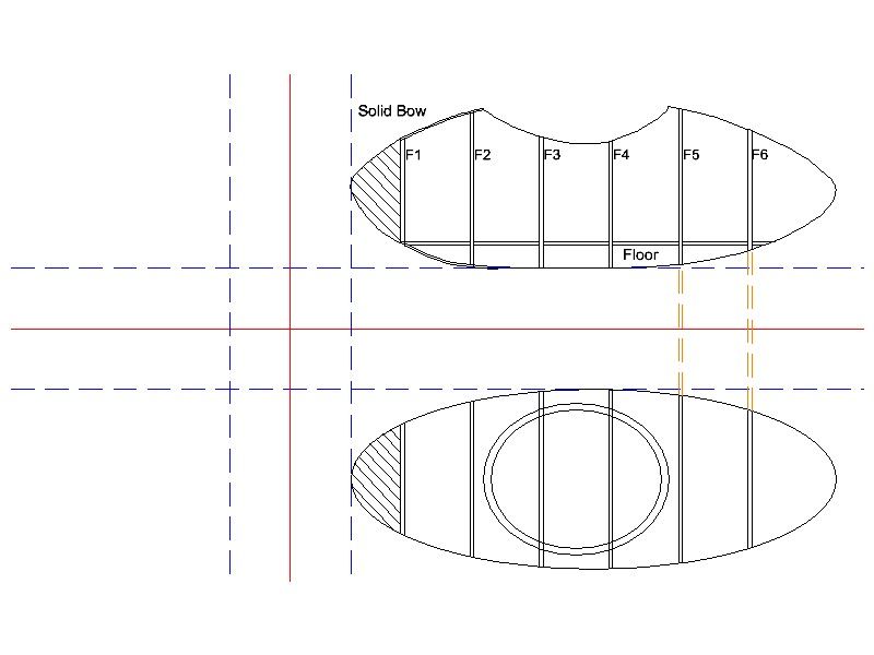
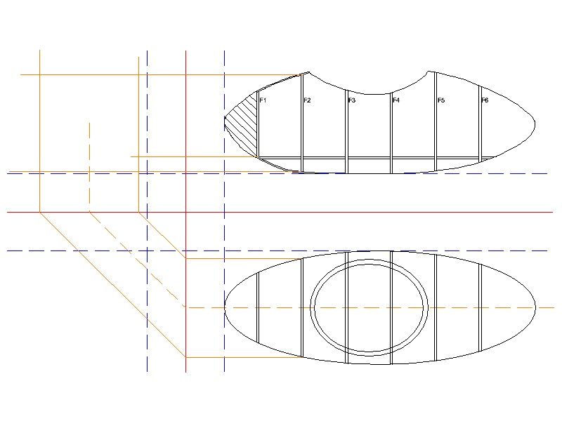
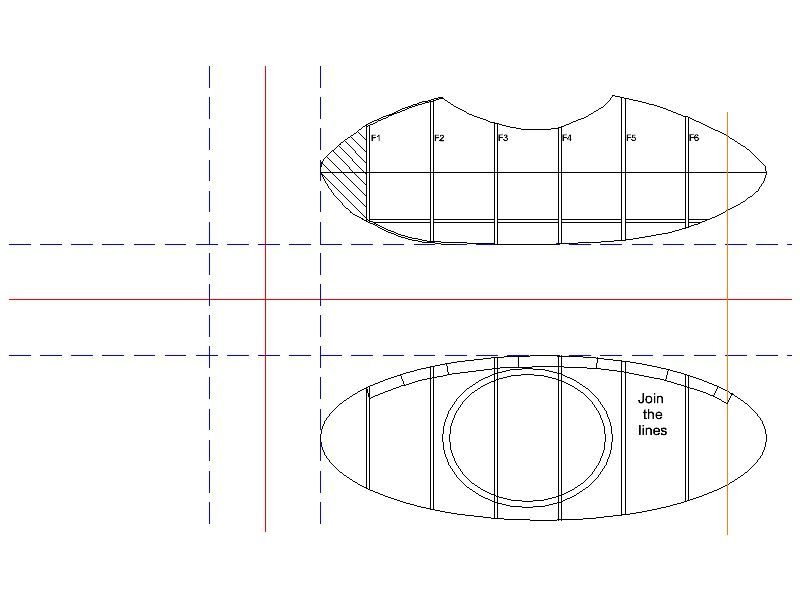
                Using the temporary vertical lines we can easily transfer the frame locations from the side elevation to the plan view. I have also included some extra details in the side elevation showing the frame numbers, extent of the solid bow and floor.

                Readers will note on the plan view how big the intended frame for the cockpit base will be, this is to allow a large enough surface area with which to establish a water tight seal.

                3rd angle 6.jpg

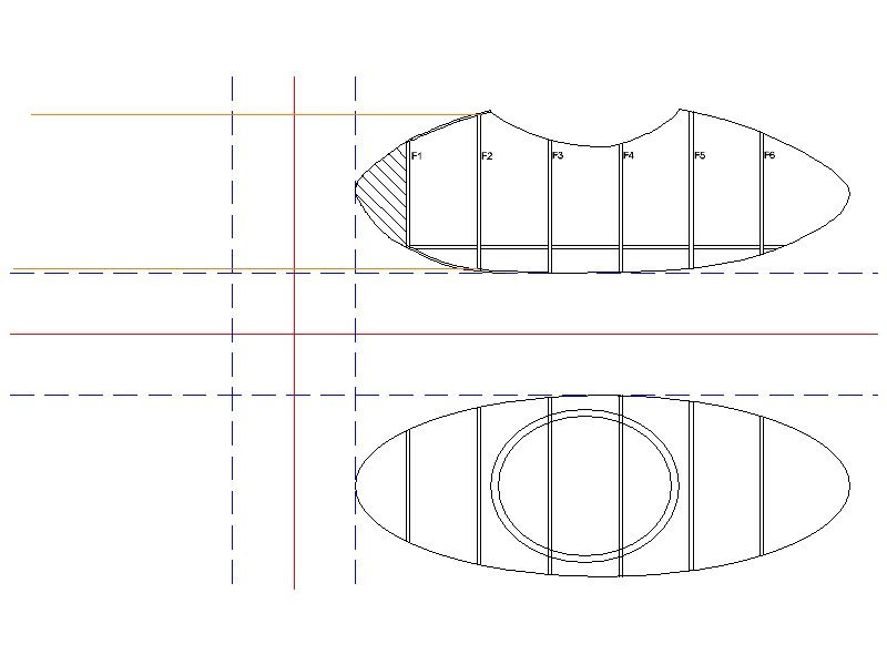
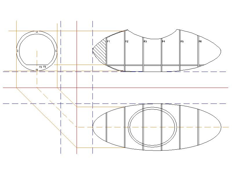
                Using the side and top elevations we can now start to 'plot' the sections through the boat. To show how this works we will concentrate on Frame 2 (F2)

                Draw two temporary horizontal lines from the top and bottom of F2 (as shown below)

                3rd angle 7.jpg

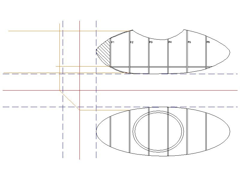
                Now on the plan view draw a temporary horizontal line starting from the side of F2 and ending at the vertical base line, continue by drawing the line at 45 degrees until it meets the horizontal base line and finally draw the line vertically until it passes the uppermost temporary horizontal line. Look at the image below and it will help you to understand all of this waffle.

                3rd angle 8.jpg

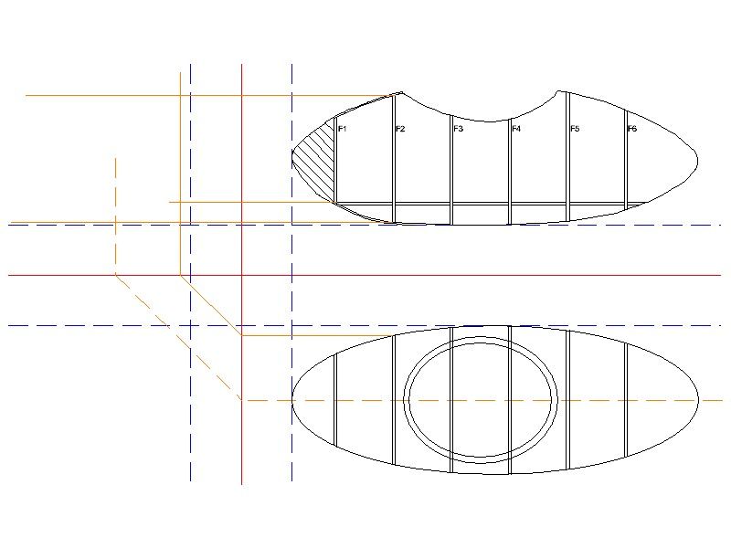
                Following the same procedure we can establish the very important centre line (as below)

                3rd angle 9.jpg

                And to complete the trio of line we follow the same procedure to draw the outer line, as below.

                In the top left corner of the drawing we have now established four lines that outline the maximum size of F2 and the crucial centre line.

                3rd angle 10.jpg

                Using the centre line as the spring point we can use compasses to plot out the curved outer and inner edges of Frame 2 (F2) we can add in the 5x5mm cut outs for the stringers & keel and floor.

                As they are identical we have now drawn F2 and F5

                3rd angle 11.jpg

                Paul

                #47980
                Bob Abell 2
                Participant
                  @bobabell2

                  Hello Paul

                  You have a mixture of 1st and 3rd angle projection

                  It's not a problem

                  I prefer 3rd angle only…..You could mention it?

                  Bob

                  #47984
                  Paul T
                  Participant
                    @pault84577

                    Hello Bob
                    I know its a mixture of styles, like I said at the beginning this is my own simplyfied version which beginners should find easier to follow.

                    #47991
                    Andy C
                    Participant
                      @andyc56856

                      Hi Paul

                      I have some of the lines drawn now. Although I need a longer T-square. Off to the shops tomorrow. Then back to the drawing.

                      Thanks for the pictures, really helps.

                      Regards

                      Andy

                      #47992
                      ashley needham
                      Participant
                        @ashleyneedham69188

                        Andy, coming back to my first post, although Paul is delivering the goods on getting a drawing up yes I think you need to get the dome sorted out before drawing too much else as the frame positions may have to be adjusted, or even the size of the whole thing !!

                        Ashley

                        Edited By ashley needham on 02/04/2014 19:32:36

                        Edited By ashley needham on 02/04/2014 19:35:11

                        #47993
                        Paul T
                        Participant
                          @pault84577

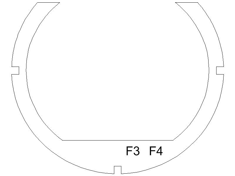
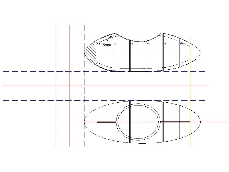
                          Using the same procedure that we used to draw F2 and F5 we can produce F1 & F6 although it should be remembered that these frames have solid centres as these are bulkheads.

                          F3 & F4 are produced in the same way but the tops are cut down to accommodate the cockpit base.

                          gup b w1.jpg

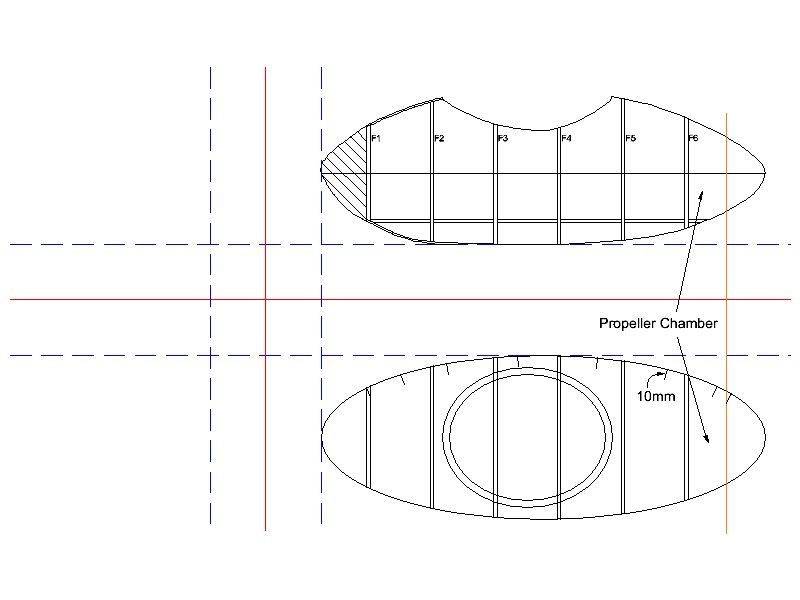
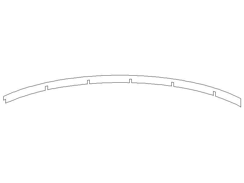
                          Moving on now to detailing the stringers, start by drawing some 10mm temporary lines as shown on the plan view below, these lines are drawn at 90 degrees to the shape of the outer hull and cover the area between F1 and the end of the propeller chamber.

                          gup b w2.jpg

                          Simply connect the ends of the lines together with a curve following the same profile as the outer hull.(see image below)

                          gup b w3.jpg

                          Remove the temporary 10mm lines

                          Now draw 5mm deep x 3mm wide slots in the stringer where they intersect with the frames, these will eventually form the cut outs that will slot into the Frames.

                          When all of the temporary and structural lines are removed you are left with a detailed drawing of the stringer which can also be used as a template

                          This drawing can also be flipped over to produce the template for the port side stringer

                          gup b w5.jpg

                          Paul

                          #47996
                          Andy C
                          Participant
                            @andyc56856

                            Hi Ashley.

                            I am working on the dome front, and will make sure the size fits.

                            Andy

                            #47997
                            ashley needham
                            Participant
                              @ashleyneedham69188

                              Rock on Andy. It is one of the defining features of the build…. Ashley

                              #47999
                              Paul T
                              Participant
                                @pault84577

                                Andy

                                Looking forward to seeing the results of your labours and hopefully these scribbling's are helping you.

                                Although it goes against the grain I have come to the conclusion that Ashleys methods might produce a better model. (but don't tell him)

                                Paul

                                #48002
                                ashley needham
                                Participant
                                  @ashleyneedham69188

                                  I will pretend I didnt read that!

                                  There is always more than one way to build a model.It must be said that it is not the way I would do it, but I have much experience of building things "on the hoof" as it were.

                                  This method will deliver. It is exactly the same method one would use to design a "normal" boat hull, and can therefore be used to design any number of things.

                                  The method I would use would be suitable for this one model only and not particularly suitable for much else, hence I am not expounding any theories.

                                  Andy, if you can understand and get the hang of this, you can build ANYTHING.

                                  Ashley

                                  #48015
                                  Paul T
                                  Participant
                                    @pault84577

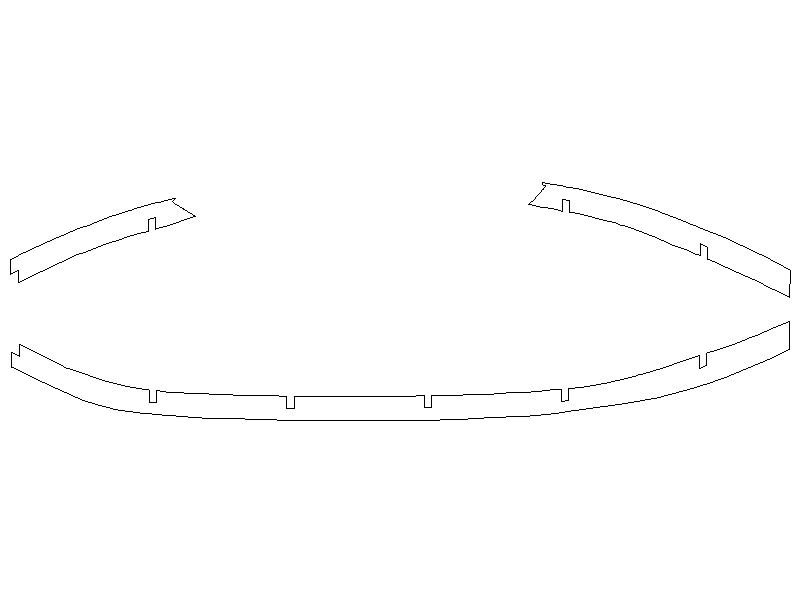
                                    Moving on to detailing the keel and upper frames

                                    By using the same method that produced the port & starboard stringers we can detail the slightly more complicated keel and upper frames.

                                    gup b 2001.jpg

                                    These parts look like this when drawn, you can see the connecting ends where the upper frames meet and lock into F1 & F6 bulkheads and the cockpit base assembly.

                                    gup b 2002.jpg

                                    Paul

                                    Edited By Paul T on 03/04/2014 19:08:20

                                    #48028
                                    Paul T
                                    Participant
                                      @pault84577

                                      Dear All

                                      I have monopolised this thread for too long so I will back off and let others explain the basic principals of design.

                                      Paul

                                      #48061
                                      Andy C
                                      Participant
                                        @andyc56856

                                        Hi Paul

                                        I have the drawings at work, had to buy a T-square, so had a go at doing some in my lunch break. I must say it is actually quite tough drawing the plan view by hand to get the curves right. Is there a drawing tool you can buy to make curves easier to draw?

                                        Andy

                                        #48062
                                        Bob Abell 2
                                        Participant
                                          @bobabell2

                                          Try cutting a piece of card

                                          Or use a flexible rule

                                          Bob

                                          #48064
                                          Andy C
                                          Participant
                                            @andyc56856

                                            Thanks Bob, forgot about a flexi rule. Will also investigate the card.

                                            Andy

                                            #48065
                                            Andy C
                                            Participant
                                              @andyc56856

                                              Or should i be trying to master a cad program. I have downloaded a free version called Draftsight. Seems complicated but i can find tutorials online.

                                              Andy

                                              #48066
                                              Bob Abell 2
                                              Participant
                                                @bobabell2

                                                Hello Andy

                                                I've had a look at Draftsight and it looks ok

                                                But when you try to print the drawing, the programme will ask for payment

                                                Don't know how much it costs

                                                Bob

                                                #48067
                                                Keith Long
                                                Participant
                                                  @keithlong89920

                                                  Bob

                                                  If you're being asked for payment by Draftsight for printing there is something wrong with your copy. If you've downloaded from the official Dassault site then Draftsight is FREE and printing is FREE – I've just tried it with my copy.

                                                  You WILL be asked to re-register every 12 months but that isn't such a big deal as any drawings that you've done will be on your computer and the newly registered or downloaded copy will open them.

                                                  Draftsight can look a bit daunting at first, but take things slowly and it will soon become a lot clearer and seem more straightforward. It is a well respected and versatile package and well worth persisting with.

                                                  Keith

                                                  #48069
                                                  Bob Abell 2
                                                  Participant
                                                    @bobabell2

                                                    Thank you Kieth

                                                    There are several versions of Draftsight…..Free download, Professional and another version

                                                    The Professional version costs….£192 per annum

                                                    Bob

                                                    #48071
                                                    Paul T
                                                    Participant
                                                      @pault84577

                                                      One of the major problems with any Cad system is that the people who wrote the software assume that the users will have more than just a basic knowledge of drafting techniques.

                                                      For example the processes of learning the complexities of plotting three dimensional curves can take months to master whereas drawing the same curve using a pencil and a curve drawing tool (or a flexi ruler) will only take a few minutes.

                                                      Paul

                                                    Viewing 25 posts - 26 through 50 (of 55 total)
                                                    • Please log in to reply to this topic. Registering is free and easy using the links on the menu at the top of this page.

                                                    Code of conduct | Forum Help/FAQs

                                                    Advert

                                                    Latest Replies

                                                    Home Forums Beginners Topics

                                                    Viewing 25 topics - 1 through 25 (of 25 total)
                                                    Viewing 25 topics - 1 through 25 (of 25 total)

                                                    View full reply list.

                                                    Advert

                                                    Newsletter Sign-up