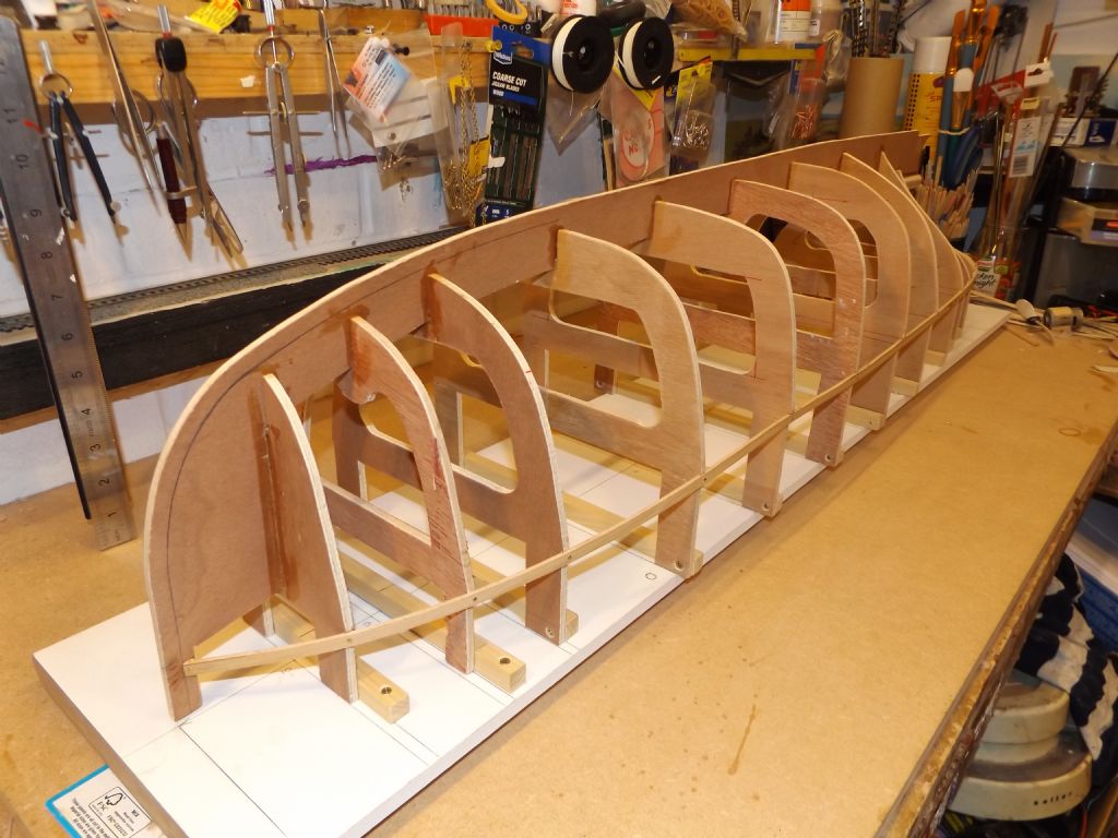
Building Jig

Advert

Building Jig

Home Forums Scratch build Building Jig

  • This topic is empty.
Viewing 25 posts - 1 through 25 (of 81 total)
  • Author
    Posts
  • #80674
    Paul T
    Participant
      @pault84577

      Dear All

      I am tasked with designing a multi-purpose building jig for model boats, which on the face of it should be a fairly simple and straightforward undertaking but the more that I think about it the more complex it becomes.

      Coming up with a jig that can work on all the different styles, shapes and sizes of hull is proving to be very difficult so I am going back to basics and asking the forum members what they deem as essential on a building jig.

      Such as:

      Should the hull be built upside down or upright?

      Do you think that a jig should have the ability to rotate the model for ease of planking or painting?

      How big should it be….my thought is that it should be 1m long x 300mm wide but this could easily be to big for a typical work area.

      I am open to all suggestions.

      All the best

      Paul

      Advert
      #7144
      Paul T
      Participant
        @pault84577
        #80677
        Chris Fellows
        Participant
          @chrisfellows72943

          Hi Paul

          Have you seen the one in the latest mag? That's for 1m. long keels.

          In fact it covers most of what you list!

          Chris

          #80681
          Paul T
          Participant
            @pault84577

            Hi Chris

            Yes I have seen it and thank you for pointing it out.

            Whilst it answers some of the needs it also fails in others, it seems fine for models with an external keel but would struggle to hold something as big as a Perkasa MTB or for that matter any kind of planing hull.

            All the best

            Paul

            #80682
            Tim Rowe
            Participant
              @timrowe83142

              Paul

              This is a tricky one as you point out. Sometimes tools that can do everything are not the best for doing anything.
              I have a Billings building slip which comes in kit form.

              I built it and that was it. I have never used it and can't see myself doing so. The channel for the keel fits one size only and has to be packed out for thinner keels. Likewise the support for the stem. The sliding piece that is used to locate frames can only do one at a time and is not that accurate. Click here to see a picture.

              I have a SLEC fuselage building jig which for those who haven't seen one, is supplied as a roll of printed vinyl to stick on a board of your choice. There are adjustable plastic supports and these are held by machine screws into captive nuts in the board. When I ordered mine I double the number of supports and added many more fixing points. I was glad I did.
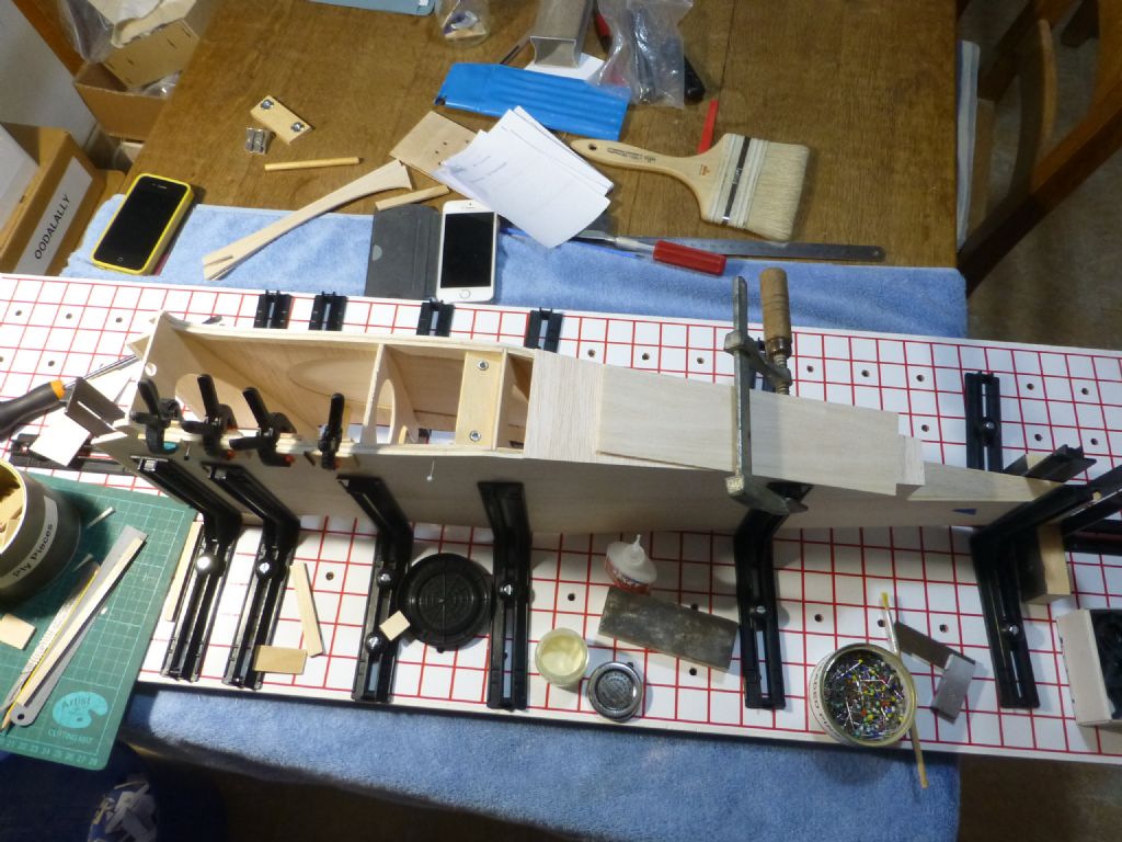
              p1280674.jpg

              Here is an aircraft fuselage in the jig and you can see that the supports can be used in any direction you like.
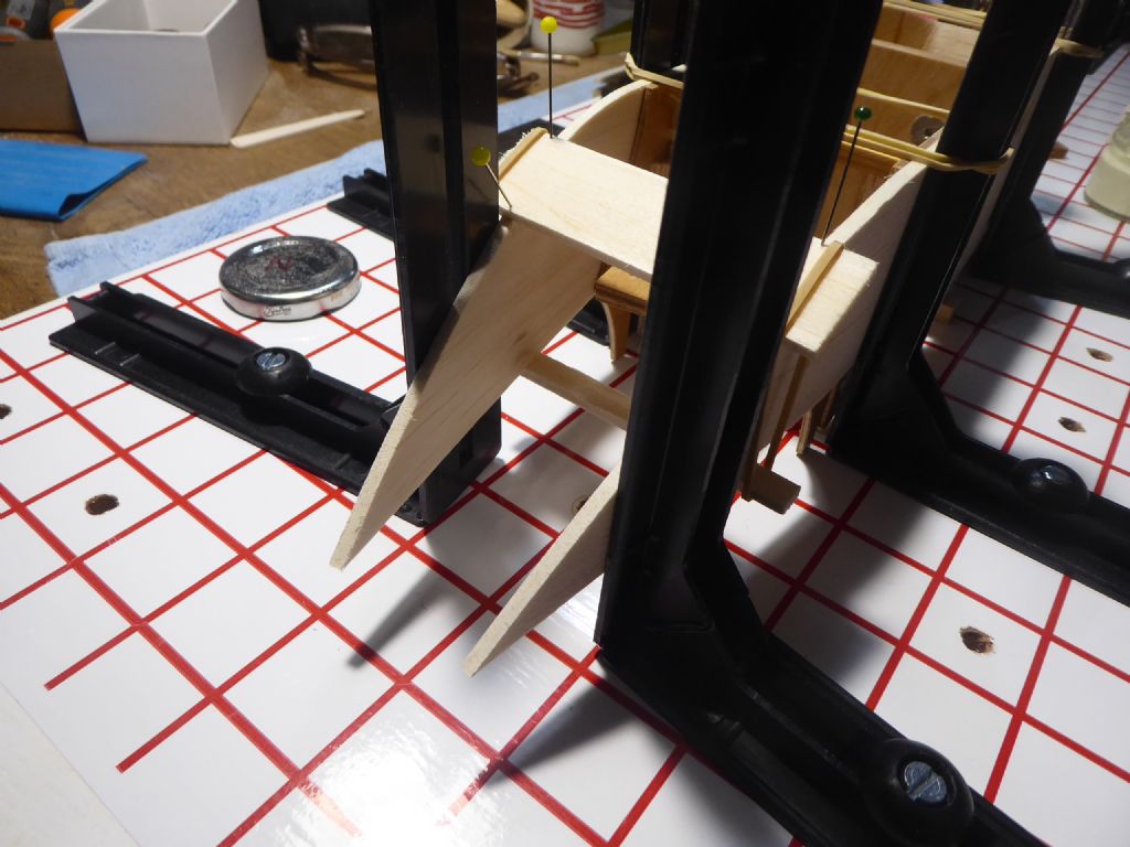
              p1050624.jpg

              Here a nacelle is under construction which ended up quite boat-like.
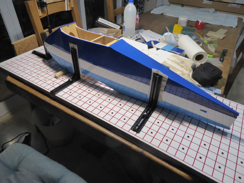
              p1040414.jpg

              And here the finished fuselage is back in the jig so I can line up the wings and tail plane exactly at right angles before fixing. So is it quite versatile.

              The basic requirement has to be a good flat board and my biggest board is 1200mm x 370mm as this is the size of the SLEC jig. Of course the printed material could be cut down. I have lots of smaller boards for sub assemblies all faced with two layers of 4mm cork which seems to last forever.
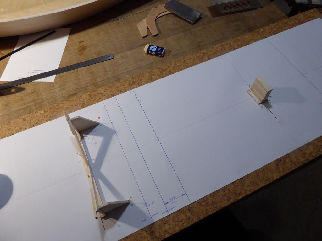
              p1010118.jpg

              My current project "Galileo" is on this board. I made a cradle to much a chosen frame station quite well forward where there is a pronounced V and the aft, flatter section of the hull rest on a set of blocks adjusted to the correct height. With the bow exactly over the line drawn on the paper and the centrelines matched up, the model can be registered easily and with good repeatability. The cork allows me to pin other supports in place.
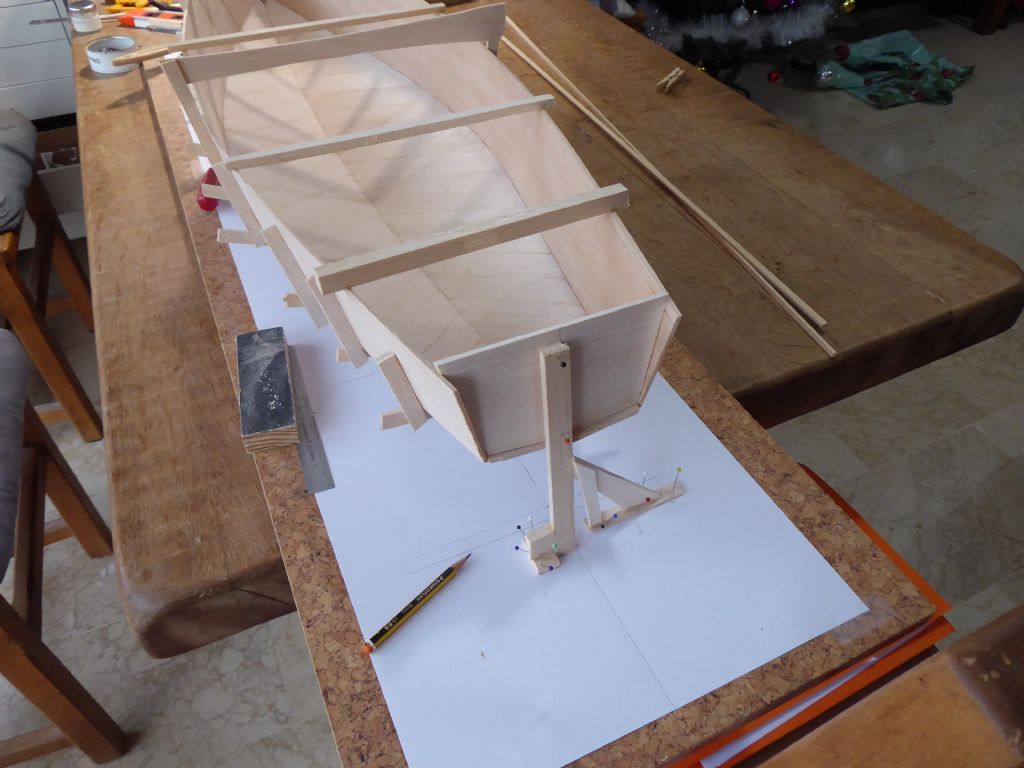
              p1010087.jpg

              Like here for instance where I had to take out a bit of twist.

              I suppose for me the best solution would be a good board and a "kit" of parts that I could adapt to make the necessary supports. Once the shape of the boat is stable you can move it around as much as necessary.

              I suppose most boats are at least started upside down.

              Tim R

              #80683
              Paul T
              Participant
                @pault84577

                Hi Tim

                I like the adaptable idea as it seems to offer the best prospects.

                Thanks for your help

                Paul

                #80684
                Ray Wood 3
                Participant
                  @raywood3

                  Hi Paul,

                  My multi use building board is the DIY version of Tim's SLEC fuselage jig, but consists of MDF 20mm thick window board comes primed, and the holes securing the bulkheads are easily filled after the first build and a coat of white emulsion and a centre line off we go again, usually comes with a rebate on one side and rounded on the other, put a G clamp on one side to to get 45 deg hull to make access for planking or sheeting easier.

                  I would think anything designed to have multiple uses will always be a compromise compared to a bespoke jig?

                  Regards Raycullamix 06.jpg

                  Edited By Ray Wood 2 on 16/01/2019 15:13:00

                  #80688
                  Paul T
                  Participant
                    @pault84577

                    Hi Ray

                    You are right about a multi use jig being in danger of becoming a 'jack of all trades' and a collection of half hearted compromises which is probably why such a piece of kit doesn't exist.

                    Your bespoke board is ideal for building an inverted hull and a method that I have used for years but now I find increasingly difficult to hold my models in 'fixed positions' whilst I work on them so I want to explore the options of a multi angle, multi purpose jig that is strong enough to hold the model in any position.

                    At the moment I am looking at using an aluminium T Slot based system.

                    Woodworking-DIY-Tools-Miter-Track-Stop-For-T-Slot-T-Tracks-Manual-Durable-In-Use Metal-Quick-Acting-Hold-Down-Clamp-Set-for-T-Slot-T-Track-Woodworking-Tool Woodworking-Miter-Track-Stop-Chute-T-slot-Track-Accessory-Tool-Durable-Useful

                    But there is a long way to go

                    Paul


                    Edited By Paul T on 16/01/2019 18:59:24

                    #80689
                    Tim Rowe
                    Participant
                      @timrowe83142

                      Paul

                      What is your preferred size of model and how heavy are they likely to get during the time you want to manipulate them?

                      Tim R

                      #80690
                      Ray Wood 3
                      Participant
                        @raywood3

                        Hi Paul,

                        Many model engineers building locomotives mount the chassis via the buffer beams on a pivoted frame so it can be turned over to any angle, mainly because of the 75 – 80 lbs for a 5" gauge loco. Similar could be done with a hull between stem & stern ?

                        regards Ray

                        #80693
                        Chris Fellows
                        Participant
                          @chrisfellows72943

                          You've certainly got a project to tax the brain cells there Paul!

                          I thought about getting a building jig for my first build but couldn't find anything really suitable. I adopted the temporary spine at deck level suggested to me on Mayhem and adapted the method by adding fingers to the spine and keel so that the hull could be worked on right way up or upside down and it worked really well with the fingers either screwed to a substantial batten on the baseboard or held in my Workmate. For a future build I'm going to use the extended frames/bulkhead method.

                          Obviously your design is complicated by the need to securely hold the hull once skinned or even completed and can't be done as per Ray's example as there isn't a chassis to fix to and is of a shape that is difficult to clamp. I think Tim's example has mileage if the side supports could slide from side to side and also be adjustable for angle and so clamp to the hull sides which would suit different hull shapes. For building the hull structure you would need to have the side supports move fore and aft and have some sort of tie between opposing pairs to position and square up the frames etc. Both of these requirements could be difficult to satisfy and be of a reasonable cost.

                          Add in being able to rotate the model and you have a real challenge. How do you attach to front and rear in a secure way and how to do it so that it doesn't get in the way of the work required?

                          Chris

                          #80694
                          Chris Fellows
                          Participant
                            @chrisfellows72943

                            Just to add to this, once I've removed the temporary spine and fingers I use a piece of non-slip drawer material on my work top which stops the hull etc. moving around. This could be supplemented with a small cushion, old pillow or piece of soft foam etc. if you want to support at an angle. Depends on the type of boat though and what you are doing and if the superstructure and other vunerable parts can be removed if working on the underside of the hull.

                            Chris

                            Edited By Chris Fellows on 16/01/2019 23:23:03

                            #80697
                            David Marks 2
                            Participant
                              @davidmarks2

                              Paul – When I first saw your posting, two things immediately came to mind. Firstly your "customer" needs to define a specification within which you need to comply. The `requirement' cannot be open ended. Secondly my idea would be to design something along the lines shown by Tim Rowe. My models are scratch builds and each build jig is bespoke to the model. My jig is a piece melamine chip board raised and braced to give a convenient height and a rigid base. The attachments which I use are blocks of soft wood, pieces of extruded aluminium angle of suitable size, cast iron angle plates etc. The choice of attachment being dependent upon the model. A Swiss Army Knife is fine, as is an adjustable spanner, but far better to have the correct tool for the job i.e. if you wish to tighten/loosen a bolt with a 17mm head, then use a 17mm spanner and not an adjustable spanner.

                              #80700
                              Paul T
                              Participant
                                @pault84577

                                Tim

                                For this project to work there can be no pre-set overall size or style of model, the adaptable jig must be able to cope with any size or shape, although I don't envisage anything larger than 4ft (ie Perkasa MTB) I think that the maximum weight capability should be around 22kg.

                                Ray

                                I had been thinking along the same lines as your buffer beam suggestion but the wide ranging differences in boat shapes and styles make this very difficult so I am looking at designing a multi finger rotating head [a bit like the old test tube clamps] that can be adjusted to grip any shape without damaging it.

                                Chris

                                I think that everyone is starting to grasp the scale of this project and the points that you raise have confirmed my own thought process but I can now see the light at the end of this particular tunnel (I just hope that it isn't the express train coming the other way) I do like your idea of using foam/sponge/pillows.

                                David

                                Your point is well made as you echo my own thoughts about the jig either being over complicated or, worse still, a fudge of half baked ideas that fail to meet the criteria.

                                Please keep your thoughts coming.

                                Paul

                                #80705
                                Tim Rowe
                                Participant
                                  @timrowe83142

                                  Hi Paul

                                  22kg! That's nearly a statutory bag of cement. With the sizes and weights you mention, safety is going to be a major factor as well.

                                  At 4' long you are going to need something that will go past each end of the boat so you are looking at something that has the capability of stretching to maybe 1500mm.

                                  Manipulation something safely at that size and weight will need some serious engineering so here's something of an idea. Think along the lines of a hog roasting spit.

                                  Description:
                                  Two frames or tripods that can be spaced apart at any interval up to 1500mm with a adjustable and lockable bars between them. Thinking welded steel angle for the frames and a hollow squares sliding inside larger hollow squares for the spacers.

                                  An horizontal axle at each end to create the "spit" like device. One end could have an indexing plate so the axle could be locked at various angles.

                                  The axles fitted with brackets that a building board can be bolted to. Long boards would almost certainly require some bracing. When the board has served its purpose as a building board you could then cut out the centre in the shape of the waterline and the boat will then sit "in" the board and clamped or strapped for rotating wherever you want. Ok, you cant get to the waterline in one go but you could pack the rim of the cut-out with hard foam or similar and the boat would sit slightly higher to vary the access.

                                  Alternatively you could keep the frames or tripods at a fixed distance to take the largest model and make a rectangular frame that could take boards of fixed width but vary the length. Crikey, you could even build two smaller boats at once. smiley

                                  Footnote:
                                  A variation of Chris's idea of foam etc is to use a collection of bean bags or bags filled with the sort of rounded grit used in aquariums. I got this tip from a fellow aero-modeller and the great thing is they have some weight for stability and can be shaped go fit around almost anything.

                                  So to end. I think you are going to end up with a basic machine and a "kit" of various universal and bespoke parts.

                                  Tim R

                                  #80706
                                  Colin Bishop
                                  Moderator
                                    @colinbishop34627

                                    I have never used a building jig although maybe that reflects the type of models I usually make. A flat piece of contiboard usually does the trick for me.

                                    Colin

                                    #80707
                                    Ray Wood 3
                                    Participant
                                      @raywood3

                                      Hi All,

                                      Looking at the more humorous side of this quest, I was involved with installing Boeing flight simulators at Gatwick, maybe the hull should be mounted in a fully gimbaled platform mounted on hydraulic rams? Or maybe a zero gravity environment where you could float around the model boat for access 😆

                                      Sorry could' not help myself

                                      Ray

                                      Edited By Ray Wood 2 on 17/01/2019 18:39:39

                                      #80708
                                      Chris Fellows
                                      Participant
                                        @chrisfellows72943

                                        Not so much for existing models, but to add to Tim's idea of a spit for rotating the models, threaded inserts could be incorporated in the bow and stern into which threaded rod could be inserted.

                                        This does throw up a further problem of how to plug the holes when the model is completed and then removing them for future work/refurbishment. Perhaps an insert to protect the thread and then filler?

                                        Chris

                                        #80709
                                        Paul T
                                        Participant
                                          @pault84577

                                          Tim

                                          I should explain that 22kg is the design load and that the actual maximum safe live load will be rated at 14kg. Like all engineers I like to add a generous safety margin to my designs.

                                          But you are correct that it has the potential to be a hefty piece of machinery and as such will probably, just as you surmise, comprise of a basic system of parts that can be formed into a range of different shapes to suit any particular project, In many ways it should mimic Legos ability to form different shapes and just like Lego be easy to strip down and reassemble.

                                          You have hit upon one of the fundamental problems facing this design with your comments about a hog roast spit in that the spit represents the X axis of a typical X / Y axis calculation but unlike the spit, which is firmly fixed in a level plane, the X axis of a model boat is very much a 'movable feast' and solving the mechanics of this conundrum is currently occupying my mind.

                                          All the best

                                          Paul

                                          #80710
                                          Colin Bishop
                                          Moderator
                                            @colinbishop34627

                                            Paul,

                                            You are clearly going for the 'one size fits all' approach but most of us humble modellers simply produce something simple to accommodate the current model.

                                            Isn't there a risk that you could end up putting more effort into the building jig than into the model itself?

                                            What is the basis of demand for such a mechanism?

                                            Colin

                                            #80711
                                            Paul T
                                            Participant
                                              @pault84577

                                              Colin

                                              Yes the idea is to produce an infinitely adjustable piece of equipment that will encompass the widest range of models.

                                              Yes it will take some effort to assemble the jig in the correct manner to suit any particular model but ultimately it should be worth it to ensure a firm and secure mounting.

                                              Why bother with designing a potential white elephant? How many people you know with dexterity problems to whom the challenge of building any sort of model is just a dream then multiply that across the UK.

                                              Perhaps I'm chasing rainbows but its worth the effort.

                                              Paul

                                              Edited By Paul T on 17/01/2019 19:23:18

                                              #80712
                                              Colin Bishop
                                              Moderator
                                                @colinbishop34627

                                                It is certainly an interesting project Paul but my recent projects have included a plastic Queen Mayt 2, a 1:48 scale 48 inch fishery cruiser, a 1/16 scale Fairey Huntsmant kit and currently a 1:150 scale 40 inch liner model. I really cannot see a universal building jig being applicable to this variety of models.

                                                Colin

                                                #80713
                                                Tim Rowe
                                                Participant
                                                  @timrowe83142

                                                  Hi Paul

                                                  Tongue in cheek I know but you did say all ideas welcome. If your Y axis is the problem so if you stick to paddle steamers ……………wink

                                                  Tim R

                                                  #80729
                                                  Paul T
                                                  Participant
                                                    @pault84577

                                                    Colin

                                                    If I could design and produce a jig that suited all types / sizes [inc those that you have specified] could you see the benefit and would you use one? wink

                                                    Tim

                                                    Trust you to put your 'oar' in smiley

                                                    All

                                                    The design has progressed to include an overhead clamping facility.

                                                    Paul

                                                    #80731
                                                    Colin Bishop
                                                    Moderator
                                                      @colinbishop34627

                                                      My building rate is too slow to justify it Paul and there would be a space probem in using and storing it in my small workshop.

                                                      Colin

                                                    Viewing 25 posts - 1 through 25 (of 81 total)
                                                    • Please log in to reply to this topic. Registering is free and easy using the links on the menu at the top of this page.

                                                    Code of conduct | Forum Help/FAQs

                                                    Advert

                                                    Latest Replies

                                                    Home Forums Scratch build Topics

                                                    Viewing 25 topics - 1 through 25 (of 25 total)
                                                    Viewing 25 topics - 1 through 25 (of 25 total)

                                                    View full reply list.

                                                    Advert

                                                    Newsletter Sign-up