Turnigy servo speed regulator

Advert

Turnigy servo speed regulator

Home Forums R/C & Accessories Turnigy servo speed regulator

  • This topic is empty.
Viewing 9 posts - 1 through 9 (of 9 total)
  • Author
    Posts
  • #5348
    Jeremy
    Participant
      @jeremy15845
      Advert
      #54581
      Jeremy
      Participant
        @jeremy15845

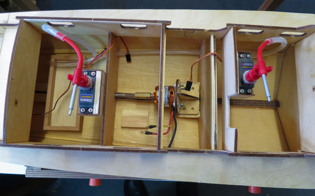
        I have got a Turnigy servo speed regulator which I hope to use to slow down the rotation of the fire monitor servos on my Vosper 1/16th scale crash tender. The problem is that I have no idea how to wire it up and the supplied manual is to put it generously somewhat lacking in detail. Normally I would connect the two servos using a Y lead from the appropriate receiver channel. I imagined that the regulator would be inserted between the receiver channel output and the Y lead, thus controlling the speed of both servos. I would very much appreciate on how this should be done. As a relative newbie to RC, an idiot's guide would be idealsmiley.

        Jeremy

        img_0802-1.jpgturnigy006.jpg

        #54587
        shipwright
        Participant
          @shipwright

          Jeremy,

          I have not used one of these devices but I have found a potentially useful diagram :

          **LINK**

          Ian

          #54590
          Jeremy
          Participant
            @jeremy15845

            Ian

            Thank you for the link which is very helpful. The connection to the receiver looks clear enough, using an extension lead with a female connector on both ends. However, I still don't understand the links from the regulator to the servos. I will be using a channel on the transmitter with the spring loaded control stick centred at the mid point with left or right rotation above or below. Do I therefore ignore CH3 on the regulator which only has direction adjust and use channels 1 and 2 for the two servos, with the change of direction coming from the transmitter? Alternatively, as I have a Y lead for the two servos, can I just use one output channel from the regulator? In the diagram, it shows one flap servo connected to CH1 and the other to CH3. I am totally confused.

            If someone can tell me exactly what to connect to what, I would be very grateful!

            Jeremy

            #54591
            shipwright
            Participant
              @shipwright

              Jeremy,

              Firstly what are the colours of the servo lead eg white – red – black (these are the colours used for Futaba servos). See :

              **LINK**

              In terms of the Turnigy diagram, the connector pins are labelled "-" , "+" and "s". These represent negative wire, positive wire and signal wire. So if your servo lead consists of white, red and black then the white wire is "s", the red wire is "+" and the black wire is "-". If your servo lead has different colours then refer to :

              **LINK**

              All 3 channels have rate of rotation adjustment but only channel 3 has facility to reverse direction of travel. Furthermore it would appear from the Turnigy diagram that clockwise rate of rotation can be adjusted to be different from rate of rotation for anticlockwise.

              But bear in mind I am unable to check my interpretation of the diagram as I don't have a Turnigy servo speed regulator unit to test.

              Ian

              #54592
              Jeremy
              Participant
                @jeremy15845

                Ian

                My wiring harnesses use JR connectors. Compared to Futaba, orange = white (signal), red = red (power) and brown = black (negative).

                I am still not clear about which channels to use for the servos. Does the transmitter provide the forward/reverse function without using CH3 or does one have to use CH3? If not, do I use CH1 and CH2 for the servos or can I use just one channel split with the Y lead?

                What throws me from Tom King's diagram is that he shows the flap servos connected to CH1 and CH3 with CH2 unused face 3.

                Maybe someone else reading this thread has used one of these regulatirs and can reveal its secrets!

                Jeremy

                #54594
                Keith Long
                Participant
                  @keithlong89920

                  Bearing in mind that I've never seen or used one of the devices, my take on the data sheet is that you can use any or all of the outputs as you need. CH1 and CH2 are effectively in parallel so the servos connected to them will work in the same sense as each other. if you connect a servo to CH3 (not compulsory as far as I can see) then you can either have that servo working in the same sense as any servos on CH1 and/or CH2, or by setting the reversing switch you can have it work in the opposite sense to the other CH1/2 servos. The speed pots set the speeds for all 3 channels together and you can have different speeds in the 2 directions.

                  I think the diagram is simply showing you that you can have the servos set so that one turns "clockwise" while the other turns "anticlockwise" – it's just illustrating an option, not suggesting that you HAVE to connect them that way. Connecting to channel 1&2 with 3 left open looks to be perfectly acceptable – there isn't anything telling you that you can't

                  Edited By Keith Long on 27/12/2014 18:28:50

                  #54601
                  Jeremy
                  Participant
                    @jeremy15845

                    Keith

                    Thanks for the explanation. That makes it a lot clearer.

                    Jeremy

                    #54960
                    Jeremy
                    Participant
                      @jeremy15845

                      Speed regulator wired up and works well. Thanks to Ian and to Keith. Note, however, that the polarity on CH2 and CH3 is opposite to that shown on Tom King's diagram. I only realised this when wiring it up as shown in the diagram and it didn't work. Fortunately, no damage was done.

                    Viewing 9 posts - 1 through 9 (of 9 total)
                    • Please log in to reply to this topic. Registering is free and easy using the links on the menu at the top of this page.

                    Code of conduct | Forum Help/FAQs

                    Advert

                    Latest Replies

                    Home Forums R/C & Accessories Topics

                    Viewing 25 topics - 1 through 25 (of 25 total)
                    Viewing 25 topics - 1 through 25 (of 25 total)

                    View full reply list.

                    Advert

                    Newsletter Sign-up