HMS Hood powering the gun turrets

Advert

HMS Hood powering the gun turrets

Home Forums Beginners HMS Hood powering the gun turrets

  • This topic is empty.
Viewing 25 posts - 1 through 25 (of 31 total)
  • Author
    Posts
  • #2214
    Eric Millar
    Participant
      @ericmillar30796
      Advert
      #38129
      Eric Millar
      Participant
        @ericmillar30796

        I have just tken delivery of the Graupner HMS Hood and have bee in touch with David McNair-Taylor regarding some information on the model.

        David tells me he wrote an article for the magazine about powering the gun turrets on the Graupner Graf Spee and stated this article would be useful in trying to power the turrets on the Hood.

        Does anyone remember the article or have a copy of it??

        Does anyone have any advise on trying this upgrade to give the already impressive model an even extra WOW factor.

        Thanks

        #38133
        Dave Milbourn
        Participant
          @davemilbourn48782

          **LINK**

          This uses a servo for each turret and a P96 Servomorph to both slow down and 'stretch' the movement of the servos. In this particluar case both servos are operated at the same time from one channel.
          Dave M

          #38197
          Eric Millar
          Participant
            @ericmillar30796

            Thanks Dave

            I'm sure I also read somewhere that HMS Hood requires 4.5k of ballast but I cannot find reference to this on the sheets that came with the ship. Putting the equilivent of 4.5 bags of sugar into the hull seems to me to be an incredible amount of weight.

            Can anyone please advise if 4.5k is really necessary.

            Thanks

            Eric

            #38208
            Malcolm Frary
            Participant
              @malcolmfrary95515

              The original displaced about 45,000 tons. Its a scale model about 1:150.

              Multiply 45000 by 2240 to get the weight in pounds, divide by 150*150*150 you get abot 32 pounds. Weigh the model without ballast, subtract from 32, thats how much ballast you need. I'll let you do the conversion to Kg.

              #38430
              Frank Wilson 4
              Participant
                @frankwilson4
                #38627
                Eric Millar
                Participant
                  @ericmillar30796

                  With regard to another model I am building – Deans Marine HMS Cossack – does anyone know what the corresponding Car Paint colour would be to get close to RN WW2 Battleship Grey.

                  #38827
                  Michael Jeenes
                  Participant
                    @michaeljeenes66772

                    Hi all. useful info all round. My partner bought this model for her grandson and has had it on display for 18months in her home. She has asked me to get it ready for the water and the gun issue has been raised. Dave M's solution appears to be a worthwhile option. I have another problem, three of the prop shafts are out of alignment and jam. I have asked 'Howes' of Oxford who sold the model to us for their advice but they have no answer other that to cut the tubes out and re-align them, question is, how? without having to remove the rear deck. They also tell me that these models are no longer made by Graupner. Any answers people?

                    Mike J

                    #38831
                    Eric Millar
                    Participant
                      @ericmillar30796

                      Having had a good inspection of my model I have decided not to power the turrets. The front turrets would be relatively easy as there is room to get to them but the rear turrets would be a nightmare.

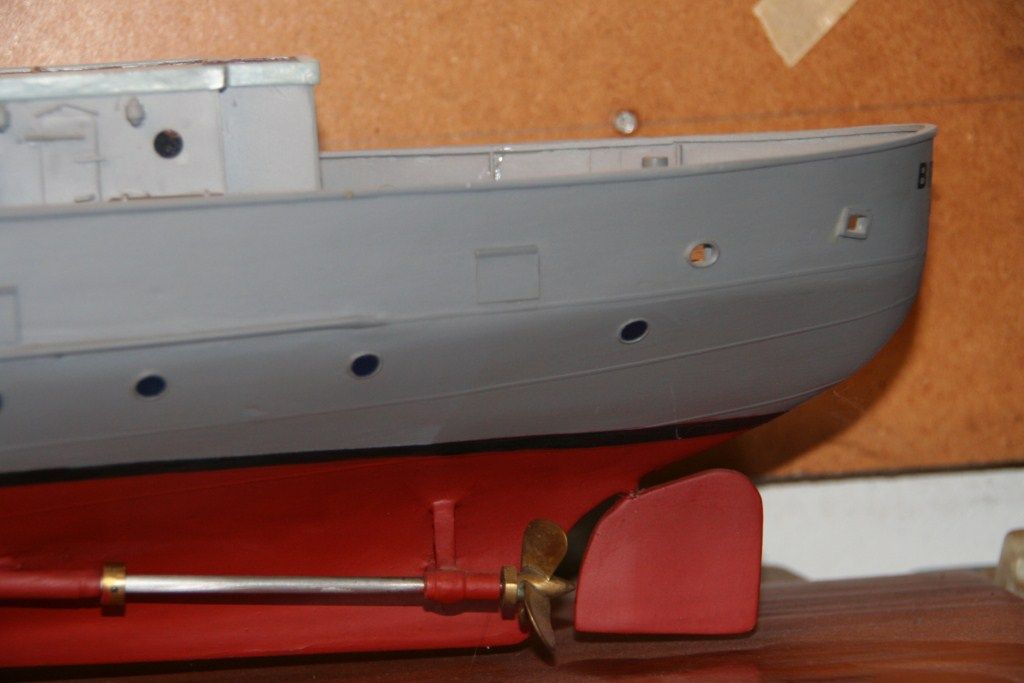
                      I also have a problem with my 2 inner shafts being out of align. This is a major dissapointment in such an expensive model from such a respected manufacturer. I have given this a lot of thought and discussed it with a fellow modeller who has the same problems with his model. We have concluded that the only option is to cut the A frames from the hull as close as possibe to the hull, allow the shafts to line up and using your modelling skills to reattach them to the hull.

                      I have yet to start doing this on my model as its to cold to go out to the workshop

                      #38851
                      Michael Jeenes
                      Participant
                        @michaeljeenes66772

                        I think that it will be possible to instal mini servos in the turrets and use 'Y' leads. It will mean that the guns will have to move in pairs unless you have a radio system with enough channels.

                        The shaft problem is not easy to resolve. I would not know how to re-attach the 'A' frames in a manner that will be secure enough to withstand the thrusts and any prop blockage that could put stress on them. Working from the inside is a non starter. What is the hull made of? GRP, Plastic, Epoxy? I have no idea and that would determine the adhesives used. Graupner don't want to know.

                        #38854
                        John Shire
                        Participant
                          @johnshire55937

                          Eric

                          I would advise caution and a lot more research into the problem of the shafts before making any changes, if Graupner can't answer the question then perhaps a search of the Internet might provide the solution.

                          Or can you take some photos of the problem and post them on here where the combined expertise of the members could be of help.

                          John

                          #38863
                          Dave Milbourn
                          Participant
                            @davemilbourn48782

                            Why not just try the models as they are? A few degrees out of alignment doesn't necessarily mean a violent, permanent turn one way. You can probably trim it out with a touch of rudder. If it proves too bad then think about surgery to fix it, but it doesn't sound broke enough to me yet. You stand more chance of doing permanent and unsightly damage by getting anxious at this stage.
                            DM

                            #38864
                            Michael Jeenes
                            Participant
                              @michaeljeenes66772

                              Hi John.

                              I have been trying to get as much info as possible on the net but keep hitting a brick wall. cutting the 'A' frames is a common solution but this is not my model and I am somewhat afraid of the potential damage and problems from the weakend frames. A photo would not show the problem, when the shafts are pulled into the hull and then pushed back towards the 'A' frames there is a 2.5 – 3mm missalignment. I have had the shafts on a granite surface table and they are running true. I will give graupner another try, may get someone else who will help.

                              Mike

                              #38865
                              Eric Millar
                              Participant
                                @ericmillar30796

                                Thanks for the info and interest.

                                I am not worried about the out of line shafts causing the boat to turn as you say this can be corrected from the transmitter.

                                When I power up the motors individually the 2 outers run smoothly and quickly, however the 2 inners run much slower and are obviously under great strain, this will obviously make the motors run very hot and potentially cause them to burn out quick quickly – Not ideal. When the shaftas are removed from the rear A frames the motors run quickly and smoothly and when pushing the shafts back into the A frame casings it is very obvious that they are out of line.

                                From what I have read so far, which is precious little about this problem, there is not much point in contacting Graupner as they apparently do not offer any help.

                                Incidently a friend also has this model and he is experiencing similar problems and has yet to make any repairs, so it is obviously not an uncommon problem.

                                I really am not keen to cut the A frames and do worry about their strength when reattached and even how to reattach then successfully.

                                I will take some pics and upload them soon.

                                #38867
                                Colin Bishop
                                Moderator
                                  @colinbishop34627

                                  From what has been said, one option might be to cut the existing A frames off flush with the hull and fabricate new ones. This can be done by using a short length of brass tubing around the shaft and then using brass strip for the support struts which locate into holes in the hull. You may be able to solder the struts in situ, but if not then metal epoxy could be used to encapsulate the struts and tube. As the whole thing will be assembled with the shaft in place you know it will be aligned accurately.

                                  If the existing A frames are misaligned I don't see any option but to remove them. If you are worried about the new ones taking the thrust of the prop instead of just supporting the shaft then the usual solution is to place a collet where the shaft enters the prop tube so that takes the thrust. The collet is usually held in place with a grub screw.

                                  Colin

                                  Edited By Colin Bishop, Website Editor on 24/01/2013 12:28:13

                                  #38871
                                  Eric Millar
                                  Participant
                                    @ericmillar30796

                                    Colin

                                    Your suggestion is similar to my thinking.

                                    I am considering cutting the A frames as close to the hull as possible but keeping them and the bearings intact,then using carbon fibre strip cut to the required length, epoxied to the inside of the A frames and then back on to the hull

                                    #38874
                                    Colin Bishop
                                    Moderator
                                      @colinbishop34627

                                      Eric,

                                      Yes something like that sounds viable but insert the ends of the carbon strip into slots in the hull for mechanical strength – I assume you were going to do that anyway. Make the holes a bit bigger than necessary so that you can be sure that the whole thing lines up right and then fill the gaps with epoxy so that it all sets in position without changing the alignment.

                                      I should think the end result would be barely noticeable.

                                      Colin

                                      #38877
                                      Michael Jeenes
                                      Participant
                                        @michaeljeenes66772

                                        Well, there are a great deal of ideas there. The 'A' frames would have to be re-attached from the outside as access to the inside is impossible through the small hatch and there is an inner moulded section containing the tubes and motors covering the location of them. My shafts stall the motors so your idea of running them and compensating with the rudder is a non starter in this case Dave. The collet idea appears to be good I will look at getting some once I pluck up courage to do the work needed.

                                        Hope semi retirement is suiting you Dave, your products are working well.

                                        #38881
                                        Colin Bishop
                                        Moderator
                                          @colinbishop34627

                                          I don't think that reattaching the A frames from the outside should be a problem if you use epoxy glue to ensure that they are firmly seated withing the hull thickness.

                                          Here is a photo of the collet on one of my (unfinished) models.

                                          brenda collet.jpg

                                          Colin

                                          Edited By Colin Bishop, Website Editor on 24/01/2013 16:34:48

                                          #38996
                                          Eric Millar
                                          Participant
                                            @ericmillar30796

                                            img_0573.jpgimg_0572.jpg

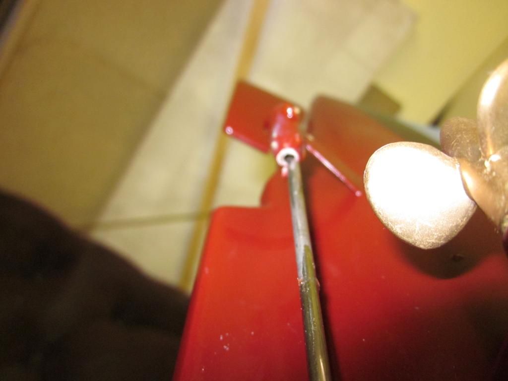
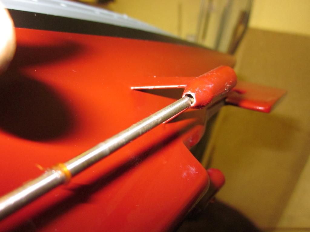
                                            These 2 pics show how far out the shafts are on the two inner A frame bearings. This is poor workmanship and definately not the quality you would expect from a company such as Graupner and on such an expensive model.

                                            Plan A was to cut the A frames close to the hull, remodel and reattach, however on closer inspection I think we need to move to Plan B.

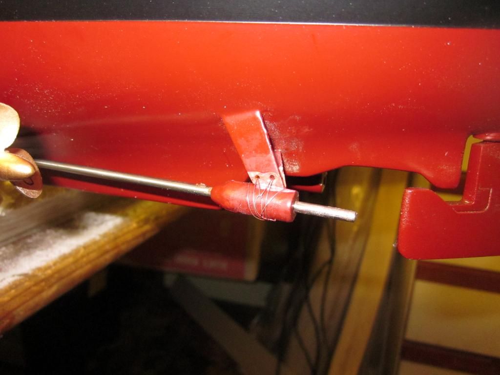
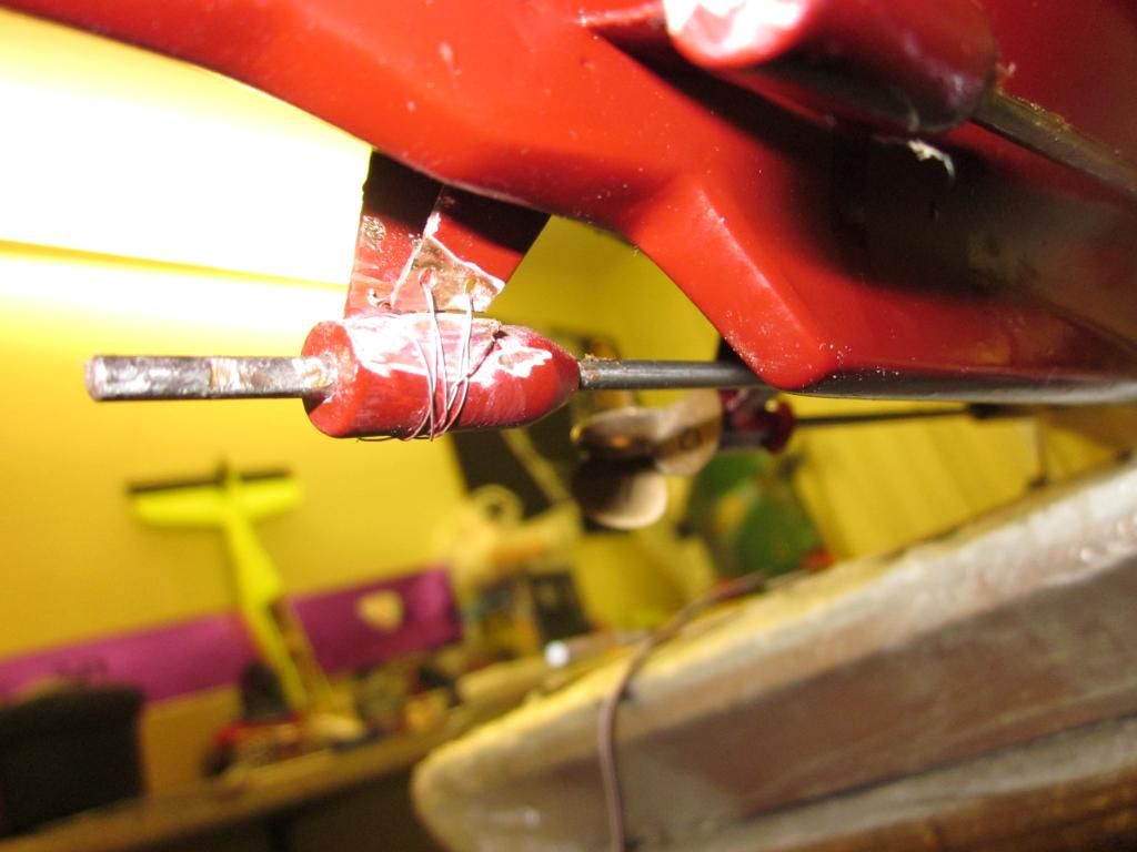
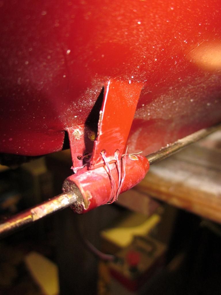
                                            Plan B – cut the bearings from the A frames and remodel at the bearing end for a smooth running fit. To reattach them drill 2 holes into the A frames and sew the bearings back on with 5 amp fuse wire for a secure fit before coating with epoxy.

                                            Any comments??

                                            #38998
                                            Michael Jeenes
                                            Participant
                                              @michaeljeenes66772

                                              Like the pics, three shafts are like this on my model. I refuse to butcher it because of the cost and once you have cut the 'A' frame you lose all rights against the supplier. Graupner are still refusing to reply but the company I bought it of have offered to have a look and attempt a repair, if it all goes wrong they will have to return the cost.

                                              #38999
                                              Colin Bishop
                                              Moderator
                                                @colinbishop34627

                                                I think you will find it was actually made in China…..

                                                Colin

                                                #39001
                                                Eric Millar
                                                Participant
                                                  @ericmillar30796

                                                  As I bought mine privately of a collector who had then for display purposes only I will not have any recourse against Graupner.

                                                  Colin it is immaterial where they were made, they are graupner models and as so graupner should have rejected them if they had done proper quality control checks. I have had other modelling equipment from China and have had no problems with them. Is this a case of Graupner having them made very cheaply then selling them at a premium price and when the problems arise virtually going into hiding.

                                                  Michael in order to get my ship into the water I have no choice but to do some remodelling. I believe you are in the same position.

                                                  #39002
                                                  Colin Bishop
                                                  Moderator
                                                    @colinbishop34627

                                                    Eric, Yes, i agree Graupner are responsible as they were selling the models under thier own name. It is also true that quality control can be a bit hit and miss in China and importers don't monitor it as well as they should. However it does mean the in a situation like this it is not possible for Graupner to correct the defective model. They should either replace it with a good one or offer a refund.

                                                    Colin

                                                    #39201
                                                    Eric Millar
                                                    Participant
                                                      @ericmillar30796

                                                      The Hood Repaired.

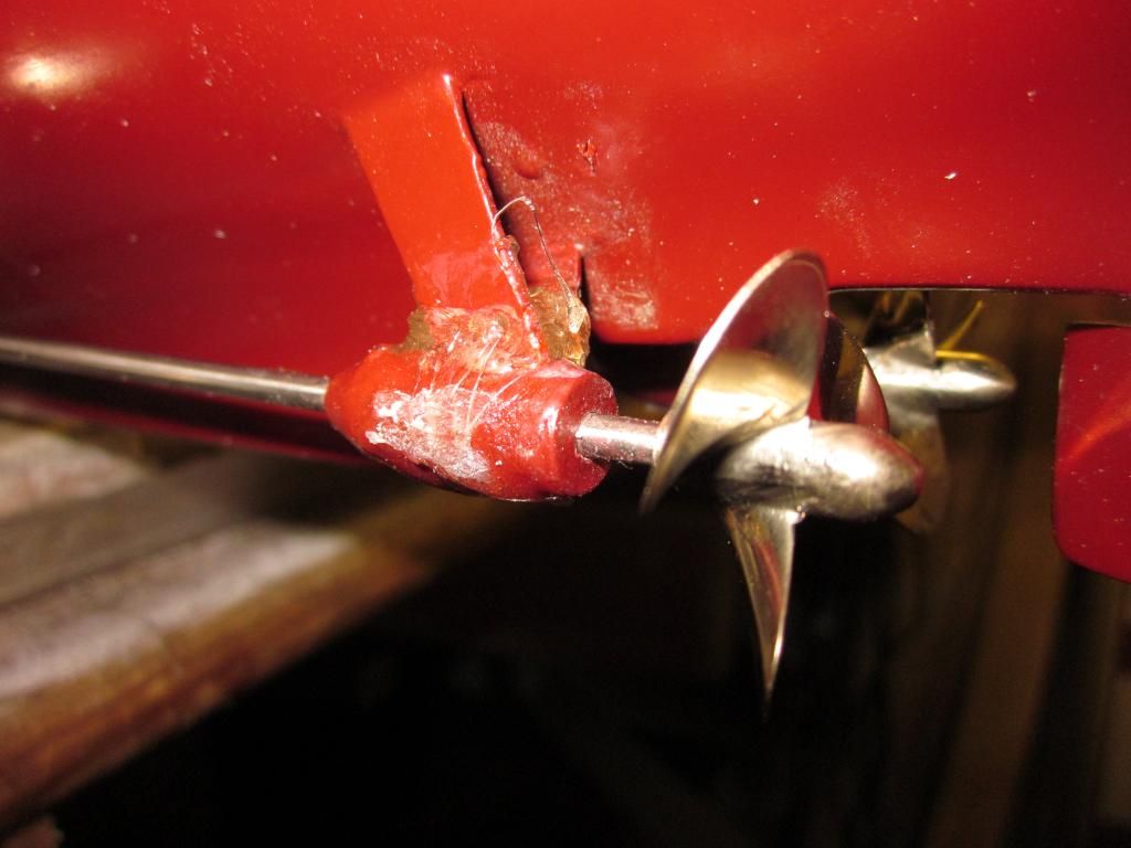
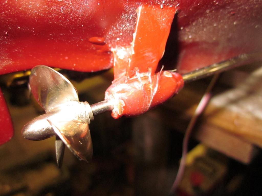
                                                      After an awful lot of thought and inspection I decided not to cut the A frames from the hull but to cut them at the bearing. So armed with my Dremel I set to work and discovered they are metal. On the port side the thickness of the Dremel disc was almost enough to line up the shaft so a little grinding and cleaning of the parts, the bearing sitting out of the way on the shaft, both were slide back into position and this resulted in a good fit. The A frames were drilled and the bearing sown on with some 5 amp fuse wire to hold firmly in place before being the complete bearing and A frame being coated in epoxy.

                                                      The Starboard side required a bit more grinding to get the desire fit but soon slide into place and received the same treatment for fixing as the port side.

                                                      I have considered repainting them but as I dont have the correct colour I had thought of painting them black but as the epoxy had dried almost clear I dont think painting will be necessary.

                                                      I must stress that very little grinding was required as the width of the Dremel disc and a little cleaning up grinding is all that was required.

                                                      A job that shouldn't have had to be done on this class of model but all in all not to arduous or difficult.

                                                      img_0590.jpg

                                                      img_0591.jpg

                                                      img_0592.jpg

                                                      img_0593.jpg

                                                      img_0594.jpg

                                                      Also sporting new Brass props

                                                    Viewing 25 posts - 1 through 25 (of 31 total)
                                                    • Please log in to reply to this topic. Registering is free and easy using the links on the menu at the top of this page.

                                                    Code of conduct | Forum Help/FAQs

                                                    Advert

                                                    Latest Replies

                                                    Home Forums Beginners Topics

                                                    Viewing 25 topics - 1 through 25 (of 25 total)
                                                    Viewing 25 topics - 1 through 25 (of 25 total)

                                                    View full reply list.

                                                    Advert

                                                    Newsletter Sign-up