When we moved to rural location some twenty years ago, I immediately started to spy out the land for modelling activities. The river flowing through the village had a small pool, the only remnant of a watermill I believe. It was rather on the small size and could be turbulent when the river was in full flow, but it was handy for testing stability and manoeuvrability. A local canal was only a couple of miles way and featured a turning bay. As this canal was little used by full sized boats it proved to be very convenient whenever I wanted to test a new or modified model. Perhaps the nicest thing about our new home was that I could quickly walk into some large open fields. Not much use for sailing a boat but ideal to rekindle my interest in R/C aircraft.
Like many of the readers of this magazine, I came into this hobby via model aircraft, plastic kits as a youngster followed by free flight and control-line models. Early attempts with R/C model aircraft were just a series of very short maiden flights, quickly followed by picking up the pieces and building the next one. After a while, R/C boats seemed like a much better idea. The idea of idea of trying R/C flying never quite left me and these large empty fields were just too tempting. Luckily, electric flight had developed since my last attempts and I soon became a reasonably competent flyer with Speed 400 powered models. In the early days, my landings were often sudden and unplanned. Amazingly, the models would usually be undamaged but the motor shafts of the motors could be bent.
Careful work with pliers sometimes straightened the shafts, but I was soon left with a number of working motors that could not be used in model aircraft but were usable in other models. They were used in small fast model boats; one even drove a large warship model but tended to get very hot. Building an airboat model thus seemed to be a very logical way of using up a spare motor and combining my model aircraft and boat experience.
Enjoy more Model Boats Magazine reading.
Click here to subscribe & save.
Design time
Having seen full size airboats on television holiday and wildlife programmes, I had the basic idea of what they should look like. A single person craft appeared to be the best option and a few layouts were sketched. My initial ideas were to use standard boating items including a six cell ‘subC’ NiCad pack. Upon checking the individual weight of all these items, it was clear that the model’s operating weight was heading for a couple of pounds, about one kilogram. This would make the model sit very low in the water and I could see the Speed 400 motor having difficulty in accelerating it to a speed where it was planing. So, what’s wrong with a bigger model you might ask? Well, a bigger model still might not be able to get across the ‘hump speed’ and start to plane. It looked suspiciously like I would end up in a vicious circle of more weight needing more power, which means more weight. It didn’t take long to realise that all I had to do to get out of this trouble was use the small battery packs from the R/C aircraft.
I usually fly with ‘AA’ sized cells. NiMH cells are now cheap and of sufficient capacity to give me up to 10 minutes powered flight with Speed 400 motors. Add a spare battery and it ought to be enough to make this model a practical proposition, especially if used a second fun model during a sailing session. Back to the drawing board and these battery packs made a model 15ins (383mm long) and 6 1/2ins (165mm) beam possible. Only now I had the worry of was it big enough to be stable!
The model was built in double quick time and tested on the local canal. The brisk acceleration and top speed took me by surprise but the handling was safe. The only thing that did catch me out was the wide turns. Using an air rudder on a flatbottomed hull made it behave more like a model aircraft. That is the rudder caused noticeable yaw before the turn commenced, unlike the immediate response of fast model boats. In fact, it is perhaps more like operating a hovercraft but without the complication of an aircushion.
 , |
Construction
This model only requires the minimum of materials. Thrifty modellers can probably build it from the content of their scrap boxes. Even if you have to buy the materials, one sheet of 1/4in (6mm) and two sheets of 1/8in (3mm) balsa will build the hull. I used a PVA wood glue for the balsa joints, the 30minute setting types allow for any adjustments before pinning the parts together without greatly slowing things down.
The first thing to do was to cut the hull parts from 1/4in (6mm) sheet. The two sidepieces had to be identical so I used the first one as a pattern for the second. The transom, bulkhead and bow pieces were glued between the two sides. It is probably best to work with the hull structure upside down on a flat surface and check that it is square before pinning the parts together. When dry, a sanding block was run over the edges to ensure that the deck and bottom sheeting would fit correctly.
The deck sheeting was then added with the grain running across the hull from side to side. The easiest way to do this is to cut the sheets slightly oversize and cut/sand back to match the sides later. You should start from the bows and stern and work towards the deck access opening. When the deck sheets reached this opening, the under deck support strips, from 1/2 x 1/8in (12 x 3mm) balsa strips were glued from the bulkhead to the transom. The hatch was cut to fit this opening and should overlap the support strips by about 1/4in (6mm). A ‘tongue’ was glued to the underside of the leading edge of the hatch and will secure it to the deck. The remaining deck pieces were added between the support strips and sides. A further support strip was then glued along the rear edge of access opening. This should produce a neat and secure fitting hatch that is reasonably water resistant.
The transom reinforcement piece had to be stuck to the inner face of the transom before gluing the bottom sheet in place. This process is the same as used for the deck sheet, without the complication of the access opening. After the glue had fully set the edges of the sheeting was cut and sanded beck to lie flush with the hull sides. The lower edges needs to be as sharp as possible to ensure that water breaks away cleanly when running at speed. The bowcapping strip was finally added and blended into match the hull. The deck and bottom sheets were examined and sanded to remove any ‘steps’ between adjacent sheets. Any gaps and dents also need correcting at this stage. A smooth bottom surface is essential for low drag and stable highspeed operation.
 , |
Surface sealing
It was found to be best to seal the exterior surfaces of the hull before adding any further items. As low weight was crucial for performance, I opted to go down the cellulose dope/tissue route. Experience has shown that with dope/tissue the model is noticeably strengthened with little increase in weight. The tissue also toughens balsa and localises impact damage, as proven by many of my ‘accidents’!
Having simple flat surfaces, it was it was easy apply the tissue in single oversize pieces. Before that the whole external surface was given a coat of thinned dope (50/50 dope/thinners) followed by a light sanding to remove the balsa ‘fuzz’. A second coat could be used if the surface is not totally smooth. The sides and transom were covered first by laying the oversize tissue in place then, starting at the centre, brushing dope through the tissue and working outwards. This method ought to avoid bubbles and creases forming. If any do occur then just peel back the tissue and relay it. The excess tissue can be trimmed off the edges with a sharp blade. The deck and hull bottom are covered in the same fashion. Light sanding and a couple more coats of thinned dope ought to produce a smooth surface.
 , |
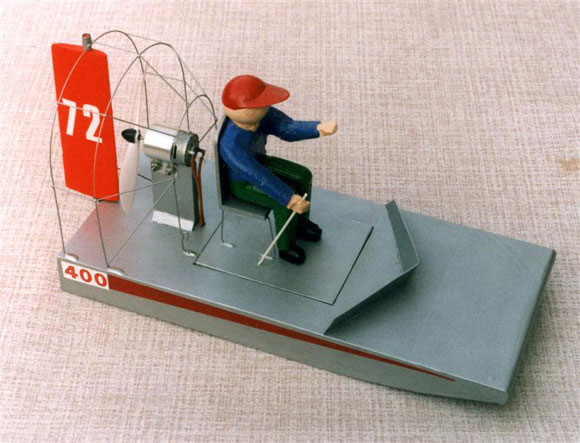
Motor pylon
This ended up being the simplest possible design I could achieve. A balsa pylon was glued to the deck with some triangular reinforcement at the base. It is important that the pylon is tall enough to allow clearance for the propeller. The pylon was then given a couple of coats of dope to seal its surfaces.
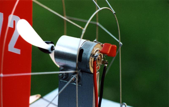
The motor was secured to the top of the pylon using a thin aluminium strap held in place by two bolts. The strap ought not to cover the cooling slots in the side of the motor case. If the motor appears to be loose within the strap then some tape can be stuck around the motor case to produce a firm grip. A loose motor can be pushed forward by the motor thrust and result in the propeller fouling the mount.
Prop guard
Full size airboats have prominent guards around their propellers for obvious reasons. Whilst not essential in a model, guards can save the fingers of inquisitive spectators and forgetful modellers. In this model, the guard also acts as the upper support for the airrudder.
The prototype’s guard was made from three arches using soft steel wire. The first arch was made smaller than the other two arches. Bending the wires around suitable cylinders made the curved sections, I raided the kitchen cupboards for cans and containers. The ends of the wires were bent into a ‘Z’ shape before epoxying into holes in the deck.
Five lengths of wire were cut and bent to join the three arches. Epoxy could be used but I found soldering to be more convenient. The guard seemed to be a little too flexible at this point so two diagonal braces were fitted between the first and second arches. Two small wire hooks were soldered to the bottom of the first arch. As designed, this guard gives reasonable protection but more wires could be added if desired. Even more protection could be achieved by covering the guard with an open plastic mesh. It’s up to you to assess the risk involved in where and how you plan to sail this model.
 , |
Air rudder
I decided to make the rudder a streamlined rather than flat plate section. This probably improves the airflow around it and was not any more difficult to make. The rudder was laminated from balsa sheet with length of dowel in the centre. After carving and sanding to a smooth section, it was treated with two to three coats of cellulose dope.
The rudder was secured to the model with two lengths of brass tubing in which the dowel would freely turn. The upper tube was fixed to top of the propeller guard whilst the lower one was held in the transom by an aluminium strap.
Driver figure
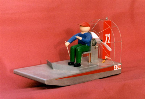
A simple seat was made from balsa sheet and wire, then glued to the removable hatch. The idea of using a commercial ‘toy’ figure to man this model was quickly discarded due to excessive weight. This lead me to make my own driver from scraps of expanded polystyrene. The torso, legs and arms were cut, carved and glued together to create a reasonable sitting posture. The head was made from a table tennis ball with no attempts at facial features although I did add a card visor to suggest a baseball type of cap. The figure was sealed with a couple of coats of domestic emulsion paint, which luckily suggested a flesh tone for the bare hands and head. The clothing was painted on. The result might not be anatomically perfect, but it weighs and costs next to nothing.
The final item added was a card spray deflector to the deck just ahead of the access hatch and sealed with a couple of coats of dope. This should avoid any water thrown over the bows from reaching the hatch.
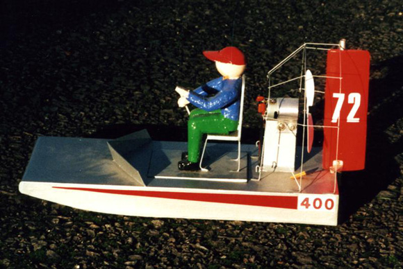 , |
Painting
From the photos of full sized airboats, they often seemed to be made from aluminium and left in their natural colour. I duplicated this by spraying the model with silver paint; two light coats followed by a clear gloss lacquer produced a good finish. For contrast, and to help me see which way the model was heading when operating at distance, the rudder was painted bright red. Some selfadhesive numbers and strips were added to avoid the model looking too bare.
R/C Installation
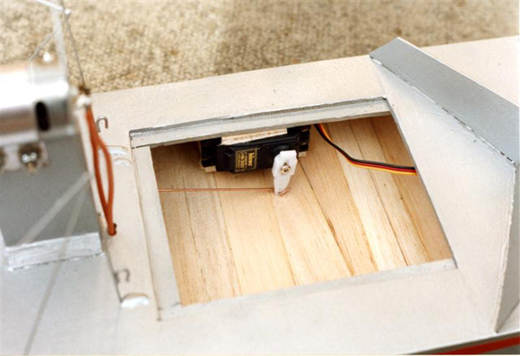
The plans show a suggested layout of the internal items. There is no reason why you have to follow this exactly, the only essentials are that the R/C equipment can function reliably and the model balances correctly. To keep the wire linking the rudder and servo arms as straight as possible I fitted the servo on its side. It was secured using packing pieces between the servo case and the hull deck/bottom sheets with spots of a latex based adhesive. This might sound odd but gives you a simple and secure mounting which can still be cut away if you ever need to remove the servo. The model currently has a small Hitec HS80 servo but a standard servo has been used successfully in earlier testing. The wire linkage runs through a hole made in the deck. To achieve some water resistance a length of plastic tube was fitted into this hole. The rudder movement required is about 20 degrees either way, a movement of about 1/2in (13mm) either way at the rudder trailing edge.
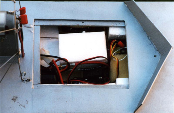
The receiver, speed controller and battery pack were secured into the hull using blocks of expanded polystyrene foam. This is a very lightweight method and provides some buoyancy in the event of any accidents. The installation of these items should be such that they are secure as any movement whilst running could seriously affect the model’s handling. Likewise, it is important to be able to easily remove and replace the battery pack. In early testing a standard speed controller was used, this featured reverse, which was found to be of little use. The model now uses a lighter ‘forwards only’ speed controller of the type used in model aircraft. Whatever type you use it must be capable of handling a continuous current of at least 10 Amps and have a BEC feature to avoid the extra mass of a receiver battery pack. The receiver aerial wire was run through a small hole in the deck just behind the spray deflector. Using a small elastic band, it can be attached to the top of the prop guard. This should give you adequate radio range provided the aerial cannot foul the propeller of course!
The best propeller to use on this model could need a little experimentation. Model shops stocked for the electric flyer should be able to offer a small two bladed Gunther plastic prop, which is perfect for Speed 400 motors. Failing that I would recommend a 5 to 6in (125 to 150mm) diameter by 3in (77mm) pitch plastic propeller. This will need a suitable prop adaptor to fit the motor shaft, the Gunther props being supplied with a neat pushfit spinner. By the way, do fit the propeller the right way around as the motor is used in pusher not tractor mode.
The hatch should still fit securely into the hull opening. To avoid it departing the model in highspeed manoeuvres I suggest using an elastic band as a ‘seatbelt’ around the driver figure. This band can be run between the two hooks shown on the front arch of the propeller guard. The model ought to run with the decks reasonably dry but for the first runs some selfadhesive tape over the deck/hatch joint might also be a good idea.
 , |
Battery packs
Commercial battery packs could be used but it is quite easy and economical to make your own packs. To get sufficient duration the Nickelmetal Hydride AA size cells take some beating. I started out using six 1200 mAH cells to achieve a powered run of some ten minutes. I’m currently using seven cell 1800 mAH packs, which naturally enough improve both speed and duration. To successfully make up your own packs you must be able to make sound soldered joints without damaging the cells and get the wiring exactly right. If there is any doubt about this, you ought to enlist the aid of someone who can (rather than claims) to be to do this or buy some readymade packs.
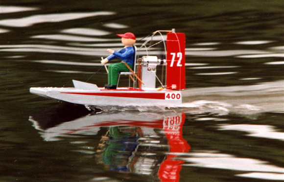
Sailing
Do not let the small size of this model fool you, it needs a lot of space to operate safely at full speed. It take both time and distance to turn this model and something like a 100 foot (30m) square water is a sensible minimum for the first runs.
Ideally, you should start with dead flatwater conditions, no wind or waves. In practice, you will probably have to settle for calm conditions with only gentle undulations moving across the surface. This model can cope with rougher conditions, but only after you have learnt to operate it first. The balance point needs checking first. The model ought to balance around the rear edge of the access opening so that it sits in the water with the stern lower than the bows. Every new model should be treated with care in its first run; to be honest we ought to start every sailing session the same way. Just advance the throttle stick half way and check the rudder response. It should do what you want but will almost certainly appear to be sluggish as it wallows around. If everything is OK, then aim it towards the middle of the water, away from other models, and hit full power. It might take a little time as the model accelerates through the ‘humpspeed’ and the hull lifts onto the plane, after which the resistance falls and speed dramatically increases.
The next thing to do is to check out the rudder control. Only apply about half rudder movement and note that the model yaws or slews in the desired direction but appears to keep travelling along the original path. The flat hull bottom has no keel with which to ‘grip’ the water and prevent this sideways motion, the model should however start a flat gentle turn. Experiment with turns in both directions and this characteristic of sliding around ought to become more comfortable. If too much rudder is applied for too long then the lower edge of the hull can ‘dig in’ to bring the model to a sudden stop in a shower of spray. So far, this has always been spectacular rather than dangerous.
The model will probably need some trimming to get the best handling. With the model running straight, it should be slightly bow high with perhaps a light slapping sound as the flat bottom hits any wave crests. If the model oscillates longitudinally (proposing), that is the bows noticeably rise and fall, then some internal weight must be moved forwards as the centre of gravity is too rearwards. If the model runs with the bows low, thus risking diving underwater, then some weight must be moved aft. Any list to the side at speed, probably due to torque reaction from the propeller, can be countered by moving the battery pack slightly towards the opposite side. If your controller has reverse then never use more than a fraction of full power. Moving astern to fast will push water over the transom and swamp the model. Steering astern is virtually impossible so reverse power is something best left for emergencies only.
Conclusions
Like many models built for some quick and cheap fun, Skimmer has proven to be far more successful than it deserves to be. The handling is different from the usual R/C model boat, no tight turns but lots of graceful wide sweeps across the water. If you were thinking of trying a hovercraft, this model would give you some handling experience.
One point to take note of is that if the motor is opened up whilst the model is on any smooth flat surface, it will try to move. It has tried to leap off my workbench and scoot across the carpet but so far with no damage. Which makes me think about trying it on some smooth snow? A final idea might be to try some club airboat racing. Several airboats tearing around a simple course ought to be exciting for the competitors and quite a spectacle for the general public.

