LEDs
GUY MORGAN illuminates us!
Enjoy more Model Boats Magazine reading.
Click here to subscribe & save.
This article is not going to tell you how I installed LED lighting in one of my boats nor will it tell you how to install LED lighting in
your boat. What it will do is to provide some background on what LEDs are, describe how to calculate the all important dropper resistor and offer one or two ideas on how they might be used.What are LEDs?
LED stands for Light Emitting Diode. The action of an LED depends on the fact that diodes made from certain compounds emit light when a current is passed through them. The physics is complex, but most LEDs use gallium arsenide in some way. The effect was first demonstrated in the infra-red region about 100 years ago but it didn’t come to public notice until 1962 when the first practical red LED was demonstrated. Since then the brightness of LEDs and the range of colours available has increased rapidly as in Photo 1, to the point where ultra-bright white LEDs are used in torches and for domestic lighting purposes to replace some filament lamps. In addition, special purpose LEDs can now be found with built-in flashing modes and multi-colours etc.
Early LEDs usually came in 3mm or 5mm diameter resin packages, but as well as smaller and larger ones of this type, please see Photo 2, surface mounted and square LEDs are now also common. Modellers will no doubt see uses for many of these types, although surface mount components are rather delicate and difficult to solder without specialist equipment.
A typical indicator LED has a forward voltage rating between 2 and 4 volts of direct current. A typical drive current for an LED, even a high-brightness one, is 20 milliamperes (mA). From this you can see that an LED dissipates a modest amount of power – just a few tens of milliwatts (mW) only. This is where the series dropper resistor comes in because it restricts the current passed to the desired figure. Passing excessive forward current is a good way of rapidly reducing your stock of useable LEDs!
Another important LED specification is the maximum reverse voltage. A diode conducts current when a forward voltage is applied, but will not conduct if a reverse voltage is applied, up to a point. This point is reached when the reverse voltage exceeds the specification and the diode fails – permanently. Given that your battery voltage is likely to be higher than the maximum reverse voltage limit for a LED, it’s vital not to connect LEDs the wrong way round. As supplied, all LEDs (except surface mount components) have the positive lead shorter than the negative one as a means of identification and many standard cylindrical ones also have a flat on the rim of the base on the positive side.
LEDs designed for torches and domestic lighting have different characteristics and if using one of these is contemplated, care should be taken to check the appropriate forward voltage drop and maximum current before use.
LEDs generally use less power and waste less of that power as heat than filament based bulbs. If not subjected to abuse they last more or less forever, so can be safely mounted in less accessible places in a model than for instance, grain of wheat (GOW) bulbs. However I would certainly soak test (leave it on for a sustained period) any LED for an hour or two and turn the power on and off a few times before fitting it anywhere that future access will be difficult. Most dodgy semi-conductor components fail on first use or soon afterwards, and often when switched on or off.
Types available
Standard LEDs are designed to radiate most of their light from the domed end, though the angle covered by the illumination varies and if critical this should be checked before purchase. All round illumination can be achieved by lightly frosting a standard LED with fine abrasive paper, Photos 3 and 4. Conversely, if a narrow beam is required, light wasted from the sides can be reduced by first painting the LED with white paint or wrapping it in aluminium foil, though to be honest it’s probably better to buy a narrow beam component in the first place. As well as these standard shaped LEDs, there is a range of ‘special’ shapes available and some of these are illustrated in Photo 5. The rectangular LEDs radiate predominantly from the diffused top surface as does another useful special type known as a Lighthouse LED. These consist of a base with a cylindrical extension which radiates from the top surface, almost like very short chunky optic fibre. I have found them in 2mm and 3mm diameters. Tower LEDs are rectangular but with a wider base and the light from them is not as diffuse as from the standard rectangular type. Two other potentially useful types are the sideways illuminating ones, which radiate from the flat side of a rectangular package and the tiny 1.6mm dome type as shown (please refer again to Photo 2).
The range of colours available has increased dramatically in the last few years. Red, green, yellow, blue, orange and white are common in both standard and ultra-bright types, though the price per unit varies a lot depending on the colour. The latest additions are pink, purple and turquoise. Some white LEDs are also made in separate warm and cool white colours as seen in Photo 6, which demonstrates the difference in a pair of tower style components. The warm white represents the colour of a filament bulb or oil lamp rather better than the normal cool white. Units with a built-in flasher and multi-coloured items consisting of two or more diodes in a single package are also easily obtainable.
Dropper resistors and supply voltage
All LEDs drop a similar voltage when passing the desired 20mA forward current. This current gives maximum brightness from the LED. If the current is limited to a lower figure, then the LED will glow less brightly, but unlike a filament bulb the colour will remain the same. The voltage drop or forward voltage is quoted as part of the LED’s specification and is around 2.4 volts for standard types. Ultra-bright ones drop about 3 volts. In the simplest case of one standard LED, the resistor must drop the difference between the supply voltage and 2.4 volts while passing 20mA, Diagram 1 . Those of you who have read my article on batteries will guess that I’m now about to use Ohm’s Law. The required resistor is found by the version of the Ohm’s Law equation, R = V/I where R (Ohms) is the resistance, V (Volts) is the voltage across the resistor and I (Amps) is the current passed. Taking a common figure of 6 volts as the supply, then the LED will drop 2.4 volts which leaves 3.6 volts to be dropped across the resistor. We know that the required current is 20mA or 0.02A so R = 3.6/0.02 = 180 Ohms. Resistors come in a fixed range of preferred values and we would normally choose the nearest larger value. However 180 Ohms is a preferred value so we can use the exact figure. Any number of LEDs with identical series resistors can be connected in parallel across the 6 volt power source up to the point where battery life is too short to be useful, Diagram 2. However, unless it’s vital to control each LED separately, there is another way. Starting with the same 6 volt battery supply, two LEDs could be connected in series and the resistor could be calculated to drop the remaining 1.2 volts, Diagram 3. I’ll leave that calculation to you.
This method saves a component and also halves the current taken. For maximum brightness, it is always advisable to limit the number of LEDs so there is at least one volt of headroom. Considering a 12 volt battery, a total of 4 LEDs could be connected in series with only one resistor or with a slight loss of brightness, 5 LEDs with no resistor. I have to say here that this method is not recommended professionally as if one LED should fail and short-circuit, then it’s likely that the over voltage will cause the others to fail as well. However there may be circumstances where the risk is justified. It’s also worth bearing in mind that if space where the light must be fitted is restricted, then the resistor can be placed at the other end of the feed wire, near the battery.
If the delights of Ohm’s Law don’t appeal, there are two dodges! In the first place dividing something by 0.02 is the equivalent of multiplying it by 50. If that still doesn’t help there is an online calculator which will do the work for you. The site also has information on LEDs and lots of other electronic stuff. See the online resources panel for details. As a last resort, Maplin and no doubt other suppliers, offer a range of LEDs with a built in resistor, designed to be connected direct to a 12 volt or 5 volt supply. Maplin also offer a small PCB unit intended to drive one or more LEDs direct from any voltage between 4 and 30 volts. This could be handy when testing secondhand LEDs and experimenting before making permanent installations.
Leaving aside the LEDs in the basic dome shaped packages, some of the others lend themselves to particular uses. For instance the rectangular ones would look particularly effective as the long tubular bulbs in the box-shaped floodlights seen in so many places these days. Both the tower and lighthouse styles offer the possibility of mounting through panels such that the top surface of the LED is flush with the surface of the panel or proud by any desired amount up to the height of the ‘lighthouse’ minus the panel thickness.
Especially for model boat builders
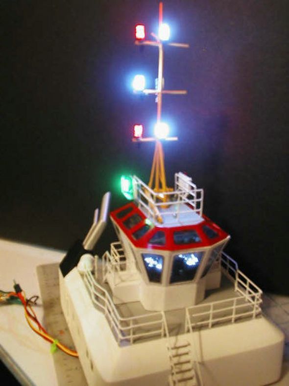
While researching for this article I came across a really clever idea. Some of you may well be familiar with the top notch modeller known as Umi_Ryuzuki who posts on at least one of the web forums. This idea is hers and I have her permission to share it with the readers of Model Boats. The basic concept could be adapted to a number of applications but in essence it involves casting lighting fixtures in a clear or coloured resin, Photo 7. That may sound like nothing special, but the clever bit is that the LED used to illuminate the fixture is included within the casting. Additional pictures can be readily seen on Umi_Ryuzuki’s website (see Internet Resources below). If you don’t want the bother of casting your own, then they and a number of other useful items are also available for sale via the same website.
LEDs are also the ideal light source when using optical fibre to get light to inaccessible places. I hope to write a short follow-up to this article in the next few months taking a quick look at this interesting application.
Internet Resources
Supplier of LEDs and optical fibre:
http://www.component-shop.co.uk/
Supplier of LEDs:
http://www.rapidonline.com/
Maplin LED driver board:
http://www.maplin.co.uk/Module.aspx?ModuleNo=47458
Resistor preferred values lists:
http://www.electronics2000.co.uk/data/itemsmr/res_val.php
A useful resistor code converter:
http://www.doctronics.co.uk/resistor.htm#convert
Umi_Ryuzuki’s Cast resin lights:
http://mysite.verizon.net/res1tf1s/id12.html

