LCM 3
John Elliott builds the 1:16 scale Speedline Landing Craft kit
Enjoy more Model Boats Magazine reading.
Click here to subscribe & save.
This is the latest release by Adrian Gosling of Speedline Models and is of a Landing Craft Mechanical 3 (LCM 3). I was visiting the Warwick Model Boat Show with our Editor in November 2010 and whilst passing the Speedline Models stand we saw the prototype LCM 3 model. Adrian explained the envisaged construction method and the various features of the model. He offered this magazine a model for review when it was ready for release and Paul Freshney took the opportunity to order one for himself at the same time. Since then a number of major changes have been made during the kit’s development, as initially the hull was to be assembled from laser cut plastic sheet, something that would be straightforward as most of the panels are flat. However during 2011, Adrian changed the hull to a more conventional moulded GRP hull which very cleverly features the ‘starved dog’ buckled panels from the welding process, common to many naval craft. The model has been designed from the outset with a fully operational bow door, controlled by a drum sail winch, with connecting cabling exactly as the full-size prototype. The two pre-production kits were finally available for us in November 2011 and were well worth waiting for. However, because Adrian had moved heaven and earth to get them ready, and of course in the interim a new master hull and mould had to be made, conventional full printed instructions were absent, but he provided loads of pictures of his own model, that some readers will have seen at the International Model Boat Show in November 2011. I needed to clarify a few details as construction progressed, but generally it was straightforward and with two brains (mine and Paul’s!) on the task, no problems of any significance were met.
It is difficult to classify any kit into a modelling experience category, but because there are etched brass components that definitely need assembly and soldering I would say the kit is suited to someone who possesses some existing model building skills.
What’s in the box?
Photo 1 is of what you get for your money. Remember that all the plastic parts are laser cut to exact size. There really is virtually no action required with the Stanley knife to separate parts from the carrier sheets or cutting to size.!
The biggest item is the GRP moulded hull which is well made and finely detailed with the aforementioned buckled plating effect. All the fabricated structural parts for the bulkheads, inner tank deck sides and floor are made from laser-cut ABS/styrene which have slots and tags to ensure accurate assembly. Smaller detailing parts are made from white acrylic sheet and these fine parts are cut exceptionally cleanly and I was amazed at the detail that can be imprinted into them using a laser. In addition, there are several hundred 1:16 scale nuts cut into one of the plastic sheets! The decks are covered in scale chequer-plate that has also been laser cut to fit exactly. In all there are 13 laser cut sheets and a moulded bow door front. All the detail castings are made from polyurethane resin and include two machine guns, cowl vents, imitation rope fenders and tyres etc. The quality was excellent with little work required apart from separating them from the sprues and cleaning up. Two large brass etched sheets contain a fold-up mount for the motors, winch and rudder servo; the rudders, keels, gun pedestals and shields, brackets for the door lifting mechanism, welding lines and many other detail parts. Running gear includes two brass tubes with bronze bearings and stainless steel shafts; two Huco type couplings, rudder tubes with O ring seals and a pair of very neat handed cast bronze four blade propellers. Other miscellaneous items included are nuts and bolts, brass rod, cord and a self-adhesive decal selection for pennant numbers and control dials. The LCM 3 was 50 feet long, so the model is 37.5 inches (95cms) long with a beam of 10.6 ins (27cms). Suggested motors (not supplied) are two 540/550 types and a Hitec type of sail winch with at least a 360 degree movement for the door mechanism. Production kits now normally include the instructions and photographs on a CD or USB memory stick.
Getting started
Normally you would read the instructions end to end and then do it again before starting, but this was not possible for the reasons already given, but to be truthful from the sequential pictures supplied it was quite easy to identify which part is which and many have identification numbers stamped into them anyway. So Bulkhead One is the first and Bulkhead Two is the second rather obviously!
I started construction with checking the GRP hull. This has been exceptionally well made with reinforcing strips moulded into its sides which help prevent the flat sides bowing inwards or outwards. Along the top there is a line above the panels which is the final trim line, Photo 2, and only 2 to 3mm above this had to be removed. The top of the hull is straight, which makes the task very simple. Coarse sandpaper was secured to a piece of 25mm x 25mm flat timber about 250mm and long run up and down the top edge, soon having it nice, straight and smooth, Photo 3. Since the central section of the hull bottom is parallel to the top edge, a spirit level and a straight edge are all that are required to confirm everything is just right.
A stand makes life easier, even though the hull will sit on a flat surface quite readily. Mine is just a milled base of MDF with two shaped bearers running lengthwise, just inboard of the skegs, to support the hull so that the deck is parallel to the base.
Etched brass skeg keels and rudders
These come next as it is best to complete the bottom of the hull work before constructing the upperworks and tank deck. This may seem daunting for a novice, but with a bit of thought and the right equipment it is not so difficult. So let’s first talk about the tools and methods required.
Like most joints of any sort, cleanliness of the individual parts is vital for a strong bond. For etched brass this is achieved by abrading with fine steel wool or an abrasive paper. The parts to be joined are then checked for fit with one another and usually a flux applied, which helps further clean the brass and prevents oxidisation during the soldering process. Normal solder wire can be used, but Carr’s 188 Solder Paste is ideal as it is solder particles suspended in a flux that is simply painted on to the joint before applying heat. Bear in mind though that its gap-filling properties are poor, so for that you will still need conventional solder wire or strip. To heat the joint a decent soldering iron (50w or more for larger items) or a butane micro torch will be needed, so one of the latter was purchased from eBay for approx. £6. With this solder paste, all that needs to be done is to apply heat carefully to the adjacent area and once the paste has turned into solder, allow it all to cool. Carr’s Neutralising Rinse will remove any ‘gunge’ that could affect the paint finish. Remember though, that all chemicals can be corrosive and hazardous to health.
The keel extensions, Photo 4, consist of two etched parts, one of which has to be folded plus a solid pre-drilled bar that will support the bottom of the rudder post. The sides of each keel extension piece were bent to shape using metal strip and wood blocks as a former, ensuring the folds were straight. These were then adjusted so that the propshaft support, which also helps hold the sides in the right position, fitted nicely in the middle. Both units were then soldered as in Photo 5.
The rudders themselves are of etched brass, folded around plain brass rudder posts (with a reduced diameter for locating in a bottom bearing) with a fold-up brass piece covering and securing the front edge of each rudder, all soldered together, Photo 6. Any gaps were subsequently filled with car body fibreglass filler.
An opening for each keel extension unit has to be made in the bottom of the hull using the part as its own template, and this process was very well illustrated by Speedline Models. Chain drilling, Photo 7, creates the outer edges of each hole and careful joining of the holes and sanding will ensure each skeg is a nice inward sliding fit.
With each keel extension and rudder support held in place with tape, the centre for the rudder shaft tube was checked by dropping a piece of straight wire through the bearing hole on the skeg until it touched the hull. This was checked in all planes for squareness and the centre for the hole(s) suitably marked on the hull which was then drilled to accommodate the rudder shaft tube. The nylon rudder shaft tubes are threaded externally, but even if the nut is screwed down as low as possible, the nut will not reach the inside bottom of the hull so a spacer will be required, Photo 8. A short length of domestic plastic plumbing pipe glued to the hull bottom and surrounding each rudder shaft tube filled with epoxy adhesive, will ensure a positive installation.
As designed, once the rudders are installed, they are permanently held in place by their skegs, so it is essential to get it right at this stage. Anyway, all was now ready for final assembly, but before that…..
Bow door access hole
My attention now went to cutting away the bow of the GRP hull for the working door. An idiot-proof template with slots for the hinge brackets, is supplied on one of the laser cut plastic sheets which when taped in position, Photo 9, enables the opening, and more important, the hinge positions, to be marked exactly with a fine permanent marker pen. A small circular saw connected to a flexible shaft on a Proxxon drill, together with files and sandpaper cut away the waste material, Photo 10. The hinge positions were checked against the dry assembled laser cut internal hull hinge bracket assembly and everything matched perfectly. A flat file, used thin edge, matched the width of the slots, so was used to remove the waste. The hull hinge bracket assembly was glued together and checked for its final position, but not glued in place just yet. All the openings had now been cut in the hull, so back to fixing the rudders, their skegs and the keel extensions.
Fixing the keel extensions
The sides of the etched brass keel extensions extend slightly into the hull and holes were drilled in the sides protruding into the hull, so that short lengths of brass rod would help hold everything in place. Masking tape was also used to keep everything square and seal the gaps between the hull bottom and keel extensions, Photo 11. The keels were glued to the inside of the hull using GRP resin and cloth/mat for reinforcement, Photo 12. This last picture also shows the supports around the rudder posts. Check and check again before going permanent, as to change things later will not be easy, BUT in truth everything is so well engineered, you will be hard put to get it wrong.
Once the glue was set, the hull was turned over, tape removed and any gaps filled in P38 filler, sanded and repeated as necessary, Photo 13. A light coat of spray primer will further reveal any minor imperfections, Photo 14. This rubbing down and filling can be labour intensive, but is worth the effort.
Rod supports extend from the bottom of each skeg into the hull bottom, Photo 15. Speedline Models provide some excellent pictures with all the measurements and precise locations. Apart from the locating holes in the GRP hull, ‘blind’ holes will be needed on the bottom sides of the keel extensions. Brass to brass joints should be soldered and where the rods pass through the hull, two part epoxy or fibreglass resin will secure those ends inside the hull. Do not allow the rods to extend more than 6mm or so within the hull, because firstly there’s little point(!) and secondly they could interfere with the internal motor and r/c installation arrangements.
Motors and servo mounting
This is a fold-up etched brass item that includes mountings for the rudder servo and drum winch as well as for the two motors. It is designed to be bolted to the hull bottom by four countersunk bolts in the underneath of the hull that are not seen in normal viewing. In addition, it is designed to align with the propshafts and makes allowance for the couplings. It also includes the brackets for the guides for the bow door raising and lowering cables and is of a very clever design, Photo 16. The downside is that it only allows for conventional direct drive to the propellers and access to the winch after installation is difficult, but not impossible. However, the concept is a ‘one stop’ installation for all the complicated internal bits, and this it does admirably.
With this assembly folded up and soldered, the propellers just fouled the keel supports as the propshaft angle was a bit too steep. This was easily solved by drilling two holes for each motor mounting screw a little lower down beside the slot for the motor shaft output boss, Photo 17 and Photo 18 shows the very nice cast four bladed propellers.
As mentioned earlier, the complete motor and servo mounting has to be bolted through the bottom of the hull, which seem unusual to many model boat builders. Speedline Models say that a smear of silicone sealant around the bolt holes will prevent water ingress and they are quite right. The holes are marked from the inside of the hull and carefully drilled, taking care not to damage the exterior hull gel coat. Before finally fixing in position, the propshaft tubes had oiling pipes added, Photo 19.
At this stage, all that needs to be done is to secure the propshafts into the hull, double checking alignment with the motor mounting, which is not permanently bolted in place just yet.
Tank deck and upperworks
Back to plastic bashing! All the parts for the main internal framework were laser cut with tag and slot location with etched numbers in each, so assembly errors should not occur. These parts only needed their edges lightly cleaned to remove any excess melted plastic from the laser cutting process, before a dry assembly run could take place. Clamps and tape helped hold it all together whilst checking everything that should be square, was indeed square, Photo 20. Gluing with Plastic Weld (or a similar liquid poly adhesive) came next. You could cheat a bit, and use blobs of glue from a heat gun in ‘hidden’ areas to initially hold everything together whilst gluing each joint with the liquid poly adhesive.
Once completely set, the structure was placed inside the hull to check its fit. Hand laid fibreglass mouldings can vary in thickness, so small tabs on the extremities of each frame may be trimmed as need be to ensure a good fit and to allow the whole thing to sit flush inside the hull with the frames not extending above the top edge of the GRP hull, Photo 21. This all proved to be a bit of a doddle, so full marks to Adrian again! It is essential to ensure that the outer hinge brackets which are part of the tank deck lower sides, align with the holes in the hinge bracket assembly, hence best to ensure everything aligns before gluing.
The main sub-deck fits over the frames and onto the top of the hull sides. It is in one piece, with cut-outs for the ribs that fit on the upper outer sides of the tank deck. The sub-deck fitted perfectly, Photo 22, so the main internal framework structure was now glued into the hull followed by the hinge bracket assembly. Masking tape will help ensure the hull sides sit up tight against the frame edges, Photo 23. Glue for this job? Well, a hot glue gun was used to initially tack everything in position and then strips of mat and tape soaked in fibreglass resin. I went a bit overboard on this…….
You may have notice the cut outs at the bottom of some frames. These are so that batteries can be installed beneath the tank deck and they allow for the passage of hidden wiring. The deck assembly drawing did not call for deck edge supports on the hull, but some were added anyway to provide extra surface area for gluing and to add some extra strength, Photo 24.
Engine room and stern area
The best access to the engine compartment is before the sub-deck is finally glued on, so I decided to take this opportunity to install the motors and servos on their etched brass mounting frame. Two 545 type motors were fitted with connecting wires and bolted to the frame using Allen key headed bolts to aid their later removal if needed (which was the case as it so happened). This was followed by the rudder servo around which two micro-switches were installed. These switch the inboard motor off when the rudders are at full deflection, thus the turning circle can be reduced without affecting performance at lesser rudder angles. The Hitec HS-78HB sail winch was fitted in position on the port side of the brass mounting frame which is etched to accept this size of unit. Speedline Models state the winch must have a minimum of 360 degrees of travel (one complete rotation) and you will note from the pictures that there is very little clearance between the drum and the hull. So it is worthwhile attaching and winding some of the winching cord around the drum before the deck is fitted. This is also a good time to explore the capabilities of the winch, noting its direction of rotation and amount of movement, so you can relate this to the bow door requirements and transmitter controls.
With everything mounted and bench tested the frame was bolted to the hull with some silicone sealant applied to the bolt heads. The supplied couplings were connected and the drivelines tested for friction free movement. GRP hulls are not always perfectly flat inside, so you may find a washer or two under the mountings of the etched brass motor mount to achieve perfect alignment. Nevertheless, this arrangement is unique in a model kit to the best of my knowledge as it is possible to remove motors and servos as a complete unit for maintenance.
Rear decking
With the running gear now fixed, the deck was glued in place. When gluing the deck to the inner framework, ensure the side decks do not go over the inner backing strip, as the top of the tank deck sides have to be glued to this strip and butt joint with the bottom halves of the sides. There are spacer strips, clearly numbered that need to be installed as well as a full across hull bulkhead that is also the rear of the engine room. All these sections are slot and tabbed and you would be hard put to get the assembly wrong. To finish off, there are longitudinal panels for the sides of the wheelhouse deck, also slot and tabbed, but make sure you get them the right way up. The hole in each is for the shaft that supports the pulleys for the door cables. Photo 25 is of the stern area thus far. We now have a basic rigid hull and the next logical item is the bow door.
Bow door
A model within a model best describes this. All the ribs and panels are laser cut and the shaped front lower section is a sturdy vac-forming, Photo 26. Once again, it is of slot and tab construction and the inner framework is built on the flat road track part of the door, Photo 27, and the vac formed outer panel then added, Photo 28. Etched brass fold-up lifting brackets need to be inserted from the inside before gluing everything together, but in truth this is a two evening job. The area that needs some thought are the door hinge supports and hinge tube, Photo 29 and the idea is simple. A tube is glued across the hinge supports on the bottom edge of the door and when the glue has set, it is offered up to the hinge brackets on the hull and marked where these will need to pass through the tube. These small sections are then cut away and a rod passed through both the tube and the hinge brackets on the hull, Photo 30.
The two end pieces of tube are unsupported, but act as spacers, so remember to keep these. As it so happened it all went together perfectly and more importantly, in line and hanging square, so full marks to Speedline Models once again. There are additional track guides to be added to the inner face of the door as well as a tube at the very top with curved matching side supports, Photo 31. This tube is machined from solid brass rod deliberately to give the door some weight when being lowered. The resin mouldings are best doubly secured with pins into the door itself and the brass rod. To complete the door all that remains are the tread plates. Once again all has been thought of and thin plastic overlay sheets represent these, but they have etched into them the positions of the welded on bars enabling vehicles to have a better grip. Included in the kit are these bars, all cut to length and they just need to be superglued in place. The overlay pieces are an exact fit, but care will be needed as they are ‘handed’. The rods are best glued with thin superglue, using its capillary action to run the whole length of each bar. With the door now complete, it was mounted on the hinge brackets, albeit temporarily, because the next task is fitting the port and starboard forward door pulley holders.
Door pulley holders
These are folded up from etched brass and are ‘handed’. The port unit, Photo 32, has three pulleys whereas the starboard side only has two, although they both look very similar These units have tangs which slide into slots pre-cut in the sub-decking. By bending the tangs in or out, it is possible to apply pressure to the tank deck sides to pull these in or out a little, because when the door is closed, alignment of the bow door sides is critical to the door shutting properly.
Chequer plate
Now is the time to fit these overlays. There are seven deck sections in all, which are handed and therefore only have one position. They fit together very well with virtually nil adjustment. In addition, there is a further single section for the conning position deck over the engine room, Photo 33. This last picture also shows the laser cut nuts added as well as part of the deck chequer plate. Gluing these chequer plate overlays requires some thought since you only really get one go after your initial ‘dry run’. It is probably best to start gluing at one end with liquid poly adhesive, applying more (in moderation) into the space between the sub-deck and overlay, then gently pressing the latter down as you proceed.
Tank deck side supports and capping rails
Capping strip (laser cut to size) for the top of the tank deck side panels is supplied and some rather nice laser cut 4mm wide hockey sticks that cover the outer edges of the external tank deck side support ribs. These must be added AFTER the chequer plate, as they pass through both the overlay and the sub-deck. Thin superglue, or liquid poly, or even a combination of the two, will hold everything together, Photo 34.
Engine room deck
This is a flat pre-cut piece of ABS that fits over the engine room and has the armoured conning position and two machine guns on top of it. The chequer plate overlay, mentioned earlier (please see Photo 33 again) is a perfect fit with no adjustment required. The laser cut nuts are only 2mm across the flats and each has been cut into a carrier sheet so will need to be removed individually and glued over the marker indents using a straight metal ruler edge as a guide. Each nut has two protective films on one side, one of the ‘carrier’ paper and the other a clear thin protective plastic. The paper is obvious, but the clear film isn’t. At first I removed these prior to gluing the nuts in place, but this became quite tedious. It became clear it was easier to glue them all in place with the paper and film uppermost and remove both a few hours later with tweezers, once the glue had set. There are cutouts in the overlay veneer for the conning position, vents and hatches, so these were the next items to construct.
The conning ‘house’ is basically much like an old style BT telephone box, but without all the windows, Photo 35, seen here awaiting the last side to be added. Brass etched weld strip is also supplied which is fixed along the vertical corners and top edges. Please note that the floor is set about 6mm up from the bottom of the sides and a finely marked line is included on the laser cut parts for this. An error by myself (and Paul) put the front panel at the back and vice-versa because we erroneously thought the etched-in panel was at the back and not the front. The viewing slits are identical however. None of this was helped by an examination of photos on the web that showed some 1:35 scale models like ours and others with the hatch on the front!
Inside is a control panel and steering wheel mounting that also includes the throttle levers and instruments, Photo 36. The control panel (dashboard) has etched brass panels and dial cases to which the supplied self-adhesive dials are stuck and they look really great.
Next were the four cowl vents and their bases, Photo 37. Each is assembled from six parts and 16 nuts in total. Each assembled base fits over a cutout in the chequer plate overlay. I found it was best to fit the scrap overlay back into its hole, so the cowl base had something to actually stick to. The resin cowls were exceptionally well moulded, but a tube inserted through the base and up into the cowl itself makes each look even better and also can be used as a locating post for the whole thing. Cross-checking with photos of the full size craft, the cowls sit upright with the opening actually leaning slightly back. The hatch and tank filler caps that are also on the this deck, are easy jobs.
The guns and their mounts were next. The pedestals are from etched brass that slot together and were soldered in the same way as other etched parts. A countersunk bolt was soldered to the centre of each of their undersides, Photo 38. This provided a proper invisible locating pin for each pedestal, provided an equivalent countersunk hole was drilled in the deck first. The guns themselves are of resin, with a stiffening rod down each barrel. They make fine models in their own right with their etched brass shields, Photo 39.
There are not really that many fittings on this boat, but in fact it still manages to look ‘busy’ once lifebelts, robes and fenders are added.
Drive battery location and tank deck
Paul has two batteries under the tank deck, but in the end I opted to put them in the stern section and just in front of the rudder posts. This meant the tank decks could all be permanently glued in place and thus be hopefully watertight. Scrap strips of plastic were glued to the tops of the lower frames and sides to give extra support and create a larger gluing area for the deck sections, Photo 40. The three tank deck pieces fitted perfectly and only required a chamfer at their butt joints. Laser marked into them are the positions of the inspection panels (with yet more nuts!) so do take care to get the tank deck sections the right way around. It is probably best to fit the overlay tread plates with their brass rods and all the inspection panels before gluing the deck pieces into the hull.
With an eye to the future, the rearmost inspection panel was made removable, so if ever additional battery capacity were required, a dummy container of some sort could be made to hide it and the battery wires passed down through the tank deck and back to the engine room, Photo 41.
Getting the door to work
With most of the major construction work completed, this task was next on he agenda. The pulleys were bolted in place and the port side slider rail assembled, Photo 42. Lifting/lowering cords were temporarily tied in place and connected to the drum and brass sliding splicing block. Putting a few turns of cord on the drum was very fiddly due to the restricted space, so do think ahead as I suggested earlier. Travel adjustment was easy to do electronically using the inbuilt software on a Spectrum DX6i Tx. A ServoMorph from ACTion R/C Electronics was handy to reduce the speed of rotation of the winch drum. It actually allows both the travel and speed to be controlled if you wish, but here it enabled the door to open and close slowly and in a ‘scale-like’ manner. For those with basic radios, a ServoMorph does enable the adjustments that can be done electronically on sophisticated r/c gear.
This test allowed me to note the movement of the splicing block in the slider rail which is critical to the success of it all and also so that its exact best position could be determined.
The brass door hinge rod looks a bit odd without ends, so brass nuts were added and drilled and pinned to make it look as though a retaining split pin was in place, Photo 43. Once painted, it all looks fine.
Finishing off
All that was left now were the fittings. Wherever possible, it is always best to pin them in place for positive location rather than just gluing. This gives extra strength and a precise location. Notable are the four side lifting brackets that are soldered together from etched brass parts, Photo 44. They could be just glued to the hull, but better to add some brass pins through the brackets and then into the hull to locate and secure them better. The holes drilled in the brackets were used as guides to drill matching holes in the hull. Hence each bracket was coded SB starboard back) etc. to make sure they were refitted in the right places.
The covers for the side pulleys at the stern were secured with two pins set into their sides so they can be removed if necessary, but they are still positively located, Photo 45.
The resin cast bollards, fairleads and other parts are very well made and require little attention, Photo 46.
Six hull exhaust and water outlets were made from two brass tubes, with piece of the larger forming the outer mounting plate, Photo 47. The insides of the outlet tubes were blanked off.
There are two dummy securing latches that on the real LCM 3 would secure the door, Photo 48. In practice, the door will remain shut for many sailing sessions. It is also not a good idea to rely on the sail winch to keep it shut as effectively the winch will be stalled with consequent battery draining, so a couple of sturdy non-scale, but not looking out of place, bottle screws help secure the door, Photo 49. They are easily removed prior to a door operating session.
Lifebelts are resin cast rings that are mounted on etched brass brackets that need to be bent to shape, then glued and pinned to either side of the tank deck and/or the sides of the conning position, Photo 50.
Sound and crew?
A sound unit from Technobots together with a matching speaker and its own power supply was squeezed into the engine room with the main on/off switches hidden under two oil drums on the stern deck. The speaker is underneath and between the motors, with the ACTion R/C Electronics ServoMorph on the port side and the Technobots sound unit on the starboard side, Photo 51.
An additional purchase from Speedline Models were the three resin cast figures, namely a coxswain, Photo 52, and two gunners, each assembled from a number of parts, but all basically the same to construct. The equivalent to 1:16 scale in military modelling terms is 120mm scale, so a search of the internet should produce links to resin cast soldiers of the right scale, but be warned as they are not cheap!
Cargo?
Well the LCM 3 could in theory carry a Sherman tank, but in practice smaller soft top vehicles were more likely. Salvation came in the form of an r/c half-track complete from Howes Models for £90. Honestly, you would be hard put to make an equivalent for less and indeed Trumpeter also offer a 1/16 scale static plastic kit version for around £140! The only snag is that both Paul’s and mine are both on the same 27Mhz frequency and there is no easy way to access the innards of the half-tracks for modifications. Okay, so we will both have to fight different battles at different times then, Photo 53!
Bath test
The model along with all its fittings, electrics and the half-track was placed in the bath to check its waterline. The model is remarkably stable, but ‘brick-like’. Anyway, it floated pretty much at the depth expected, so was duly marked.
Painting
I prefer to paint everything once construction is complete rather than as I proceed with building, so everything was now disassembled. The data provided by Speedline Models indicated a number of different possible paint schemes with blue, light grey and dark grey upperworks and below waterline colours of red, blue and black, or indeed an overall grey colour. In addition, some internet pictures showed camouflage versions. I opted for grey upperworks and a black bottom, surmising one couldn’t go far wrong with that combination.
Everything was cleaned and checked for imperfections before priming. Fittings were mounted on wooden blocks or stripwood. The first primer coats are almost sacrificial as they will show the blemishes and highlight areas that require further attention. There was a noticeable problem when spraying the tank deck ‘box’ area because one was spraying into a closed box and the ‘bounce back’ spray caused a grainy and hairy finish. Paul suggested I only spray one side at time, allow to dry and then do another and so on, or mask off the non-target sides whilst painting the others.
With a satisfactory primer coat finish, the main colour coats could be applied. As the bulk of the model is grey, this is all straightforward work. An airbrush is ideal for this task, but rather than use Humbrol enamel tinlets, a local car paint shop supplied me a 250ml tin of a suitable satin grey enamel for this model. This proved to be more economical than purchasing numerous tinlets. The paint supplier was able to match to a Humbrol colour using their own charts. I am not too sure though how many cars there are out there in warship grey! The purchased 250ml tin of paint performed exactly like Humbrol, needing to be diluted 50:50 and drying in roughly the same time span. Several thin coats were applied and lightly rubbed down between until a depth of colour was achieved.
Marking the waterline and then masking the rest of the hull was easy, since the sides and stern are basically flat and the line is parallel to the deck edge. Humbrol Satin Black No. 85 was used for the underwater part. This covers very well and no more than two coats will give a decent depth of colour.
The self-adhesive decals include pennant numbers in black, red and white, so you have a good choice. M543 was what went on this model and Paul chose the same, but reversed the 3 and 4 to make M534. Several light coats of satin varnish sealed everything nicely.
Weathering is optional on any model, but these landing craft cry out to be given the treatment, even if only in the tank deck area since tracks and wheels will mark the steel anyway. The degree of weathering is a personal choice, but expertly applied it will highlight the starved dog plating which can be no bad thing. The hull is steel, so rust is appropriate, but also remember that many of these craft were ‘use only once’, so might have been quite clean before their use. Lifecolor have a range of weathering paints that readers might like to consider?
The trick is not to overdo it all, so that from two or three metres the weathering is not too obvious, Photo 54.
Final assembly and on the water
Putting everything back together and gluing the fittings in place was only a couple of evening’s work, so with batteries charged and final checks completed it was off to the lake with our Editor for sea trials.
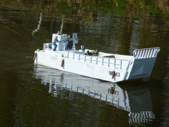
Performance was good and not too fast but with a realistic top speed. It manoeuvred well and with the aid of the micro-switches it could nearly turn on the spot. Because of the blunt bow, I thought water may have entered the tank deck through the small gap at the bottom of the door owing to the bow wave. Surprisingly there was absolutely nothing and we would conclude the design of the whole thing is such that the pressure of water is deflected away from the door hinge area. Now for the bad news!
Things were going fine for the first ten minutes when performance markedly declined and after another five minutes the model was removed from the water. On inspection, the motors were too hot to touch and the battery was flat. Everything was free turning, so it was the motors that were at fault. As it turned out, I had installed 545 type motors with a maximum efficiency drain of six amps. A couple of low drain Caldercraft CEM550s type, drawing only one amp on no load at 8.4amp and rated for 2.4v to 12v, were obtained from Cornwall Models and solved the problem. It was not an easy task extracting the high drain motors and replacing them, but it was done with a few curses along the way. A few days later we were back at the lake and this time also with Paul’s LCM 3. Speed was the same, but battery longevity much improved and after 40 minutes the motors were almost cold and the battery still had capacity, Photo 55.
Conclusion
This was a pre-production kit, so full instructions were absent, but the photo sequence supplied was easy to follow. I have now seen the draft final instructions (February 2012) which are a combination of text and pictures and they look fine to me. The quality of all the parts was first class and all the laser cut parts went together with great accuracy. There are some novel ideas included, such as the starved dog look of the GRP hull and the combination mount for the motors and servos. The completed model does looks superb on the water, especially with the crew. On the water performance is realistic and she is quite manoeuverable which might seem surprising for something shaped very much like a brick!
The price at the time of writing is £495 + £45 for the three figures. The kit is available direct from Speedline Models Ltd, Windsor End Cottage, Windsor Street, Burbage, Leicestershire, LE10 2EE, England, Tel: +44 (0)1455 637658 or 07983 578804.
The photos below show model detail, the finished model and LCM3 afloat.
Useful websites
Speedline Models Ltd: www.speedlinemodels.com
Action R/C Electronics: www.action-electronics.co.uk
Batteries: www.component-shop.co.uk
Cornwall Models: www.cornwallmodelboats.co.uk
Glues (5 Star Adhesives): wwwfivestardistribution.com
Howes Models: www.howesmodels.co.uk
Lifecolor (The Air brush Company) www.airbrushes.com
Micro blowtorch: www.tooltime.co.uk
Hitec sail winch: www.servoshop.c.uk
Solder: www.finescale.org.uk
Technobots: www.technobotsonline.com

