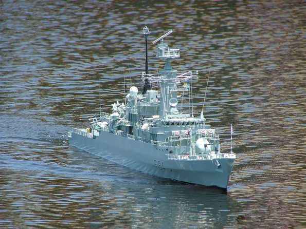
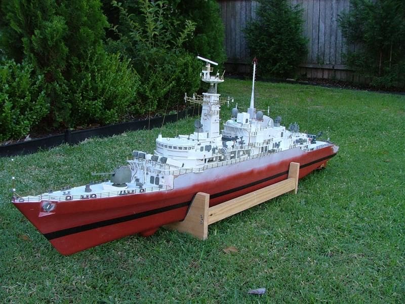
John Slater builds the APS Models 1/72 scale semi-kit of this Type 21 Frigate.
(This is not a step by step description of the building of this fine model, but more of a general description of the challenges faced and overcome. The model is based on a 1:72 scale semi-kit manufactured by Alan Pew of APS Models in Australia Editor.)
Why the Type 21?
Enjoy more Model Boats Magazine reading.
Click here to subscribe & save.
After many months of scratch building a 1/72 scale aircraft carrier and realising the need for a more portable project and not wanting not to build a hull again anytime soon, I decided to scan the APS catalogue for a new challenge, but what to build?
The answer came to me through my fathers attendance at the 2005 Task Force 72 Regatta in Australia. He was amazed at the models and having no excuses being retired and after some prodding, we decided that we should build something together. My father took a great liking to those vessels that seem to handle the conditions very well and to uses his words; handle like a sports car. With the words sports car, the RN Type 21 sprung to mind and after dad saw a few photographs, the semi-kit was ordered from Alan Pew at APS. In fact two were ordered, the original intention being that we would each have one.
On the subject of good handling, I was warned by quite a few Task Force 72 members that the Type 21 would prove a challenging build as those built thus far, had top weight problems, a bit like the real ships. Ian Howard, a fellow member of Task Force 72, stated that his model of HMS Avenger was extremely touchy, thus confirming this general view. However, he informed me that he had used timber decks and 1mm styrene for the superstructure and confessed that he just built the model a bit on the heavy side.
I like a challenge and to be forewarned is to be forearmed. My father and I really liked the lines of the Type 21 and so we were happy nonetheless with our decision. Our decision was reinforced when researching the class, which involved the purchase of the excellent book: Modern Combat Ships 5, Type 21 by Captain John Lippiett RN. I have high praise for Navy Books (www.navybooks.com), the Royal Mail and Australia Postal Service that had the book delivered to me in Australia by ordinary air mail just three days after it was ordered and this was four days before Christmas!
John Lippietts book is extremely informative of these ships, and I believe to be a most definitive source of information which it certainly was for us. That said, there are some areas of interest to the modeller that are lacking, such as specific paint colours applied in different areas and the timescale when the ships received particular upgrades, if any. The bottom line though is that it is an excellent book, written from a balanced positive personal perspective that clearly identifies some of their deficiencies as well.
In contrast, I soon found on the internet a plethora of scathing criticism of the ships, naming stability problems, aluminium superstructures that burnt very well, lack of room and top weight too excessive for mid-life upgrades. Much of this criticism failed to factor in the views of those who crewed these ships risking their lives and who came back time and again to serve on them. Their popularity amongst the crews for their generous living quarters, general working conditions and their effectiveness, seemed absent. So too was the fact that HM Ships Antelope and Ardent absorbed a tremendous amount of damage in the Falklands War of 1982 prior to their loss. Yes, the aluminium superstructures caught fire, but what might have happened if a contemporary ship were attacked in the same way?
The book assisted with actual ship choice for the model, as we liked the concept of a vessel equipped with a Lynx helicopter, Exocet missiles and to a fair degree the colour contrast of green decks and the colourful Cheverton launch. With those colours alone, we were looking at a late 1970s to just pre-Falklands era ship. The book revealed that HMS Ardent had Exocet missiles and a Lynx before the Falklands War. HMS Amazon had a Lynx for trials earlier and indeed HMS Arrow was actually the first to be assigned a Lynx.
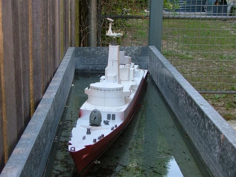
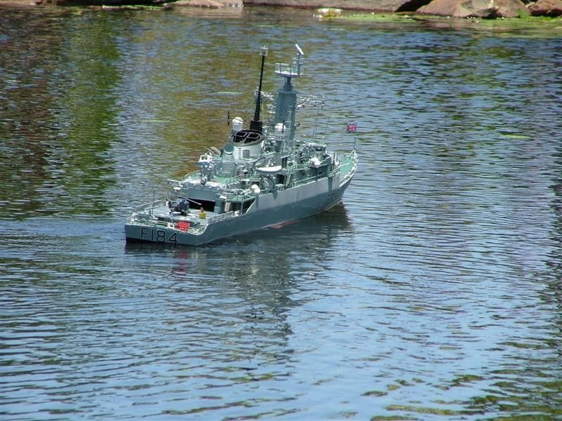
So we decided on HMS Ardent and furthermore as Task Force 72 operational Type 21s thus far consisted of HM Ships Active and Avenger, we would now be adding to this Type 21 flotilla. I should point out again that we initially intended to build two Type 21s, the second being HMS Arrow and both scheduled for basic construction by me with this second model then being detailed, fitted out and finished by my father. He (my father) unfortunately then fell head over heels for model yacht racing, so HMS Arrow was paid off prior to her completion to another Task Force 72 member. This article therefore focuses on my HMS Ardent.
Ian Howard very kindly gave me his plans for HMS Avenger, a similar ship of the class. One perplexing issue that we had to resolve was what masts and mast equipment were on HMS Ardent circa late 1970s. The mainmast, just in front of the funnel had gone through some noticeable changes, and the foremast, just behind the bridge, had electronic countermeasure sensors (ECM) additions that were quite noticeable features. I am very grateful to Michael Brown of Task Force 72 for supplying me with a good number of date assigned photographs for all the ships of this class, which with the many photographs in the book made recognition of relevant features for the year of build of my model much more accurate. Michael also provided some great on board shots of HMS Amazon and of a model of HMS Active that he photographed on one of his frequent UK visits to Portsmouth Historic Dockyard. Michael is our local RN painting expert and was also very quick in giving me exact colour formulas for the decks and hull.
The APS semi-kit
Allan Pew of APS Models does great work in all the various 1/72 scale kits and semi-kits he supplies. What you get is all of very high quality and at a reasonable price. The kit came with:
GRP hull
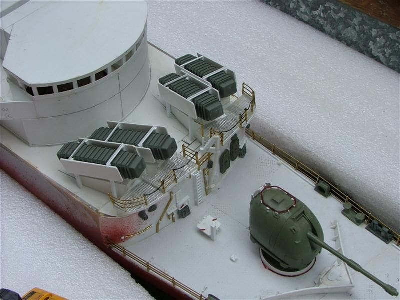
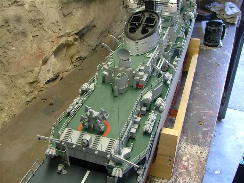
4 x Exocet missile canisters
4.5in Mk 8 gun
4 x 20mm Oerlikon machine guns and mountings
2 x Triple STWS torpedo tubes
1 Seacat mount
2 x ECM aerials
2 x Chaff launchers
2 x Sonar decoys
2 x SM6 Sea Rider inflatable boats
2 x 912 Radar directors (tracker radar)
1 Abbey Hill radar
4 x Witches Hat antennae
25 x watertight doors
2 x electric winches
30 x bulkhead light fittings
10 x liferaft canisters
1 x Cheverton launch
1 x 27ft Motor Whaler hull
10 x bollards
12 x fairleads
2 x signal lamps
10 x fire hose racks
1 x stern hoist
3 x anchor windlasses
2 x anchors
Also included were stainless steel propshafts, A-frames, stuffing boxes and rudders.
What I needed to buy were:
Propellers (optional extra from APS)
Motors
Speed controllers, batteries and r/c
Building materials, styrene and wood, brass rod etc.
Consumables
What I needed to build were:
The funnel, superstructure, deck and masts plus other small detail parts as well as install the shafts and motors etc.
Now, the current semi-kit includes a few extra detail parts to that which I received. A most useful addition is that you now receive the funnel, which is of lightweight GRP, the master of which I made and it includes the mast base just ahead of it. In addition I made moulds for various ventilator exit grills and Type 992 radar director tracker bases. All of these are now standard features of the semi-kit.
Starting construction
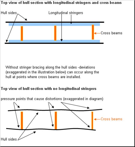
The very first job upon receiving the package is to check that all the parts are included, then to give the hull a good wash down with some warm soapy water and give the outer hull a light rub down with fine wet and dry sandpaper. The next task, save for building a secure boat stand, is to affix lightweight timber strips along the entire length of the hull edges, suitably positioned to support the decks. These stringers help maintain the hulls shape. These longitudinal deck edge stringers allow cross sectional beams to be inserted into the hull, maintaining the correct profile. If you fix cross section beams to the hull without reinforcing the deck edge, the sides will tend to bulge around those beams.
The lightweight stringers and cross sectional supports were glued in place using 24hr epoxy. A word of caution here, is that some five minute or fast setting epoxy glues are actually not fully waterproof when cured.
Sonar dome
The next stage in the construction was to fit this to the hull. To heed the warnings of those who have built the kit previously, we sought to keep weight as low as possible. In this respect my father, a keen r/c yachtsman hit upon a great idea. He suggested we make the dome out of solid lead. To do so would provide a lead like keel in a position very low down, actually lower than the bottom of the hull and the ballast could then be disguised as the sonar dome. My father built a ceramic mould and cast the dome. Two stainless steel bolts inserted into the lead secured the dome to the hull.
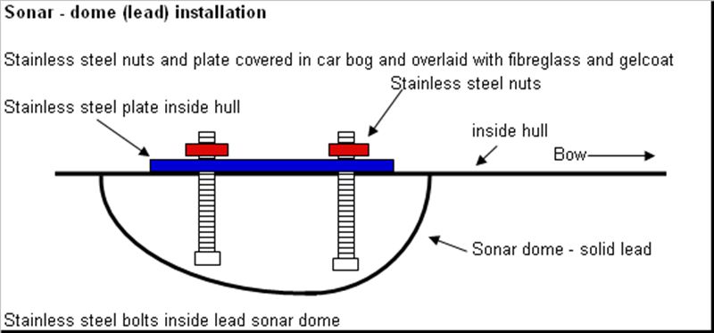
The relatively rough outer skin of the lead sonar dome was then filled with fibreglass filler and sanded to shape. This outer skin was then also coated with a layer of gel coat with a special drying agent added (gel coat remains tacky unless air is excluded or a special additive is included the catalysed mixture). Inside the hull a stainless steel plate was inserted over and around the bolts to spread the load and a layer of chopped strand mat and fibreglass resin secured everything permanently.
Running gear and tank testing
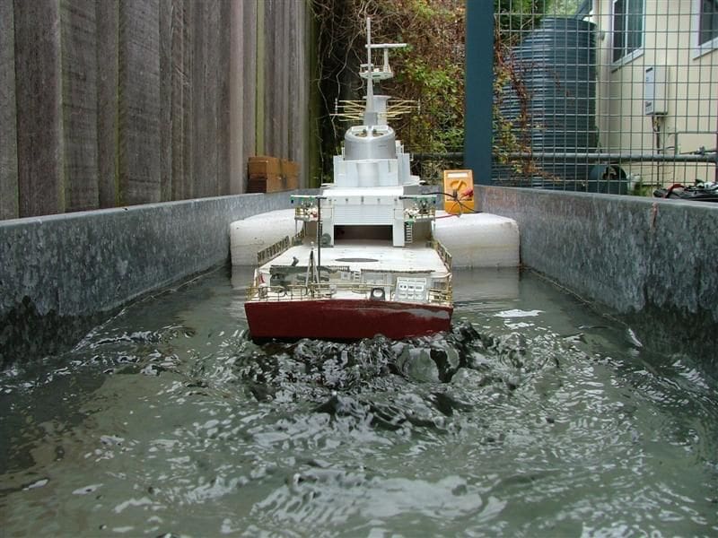
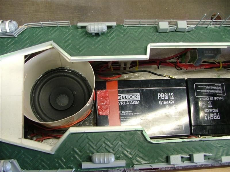
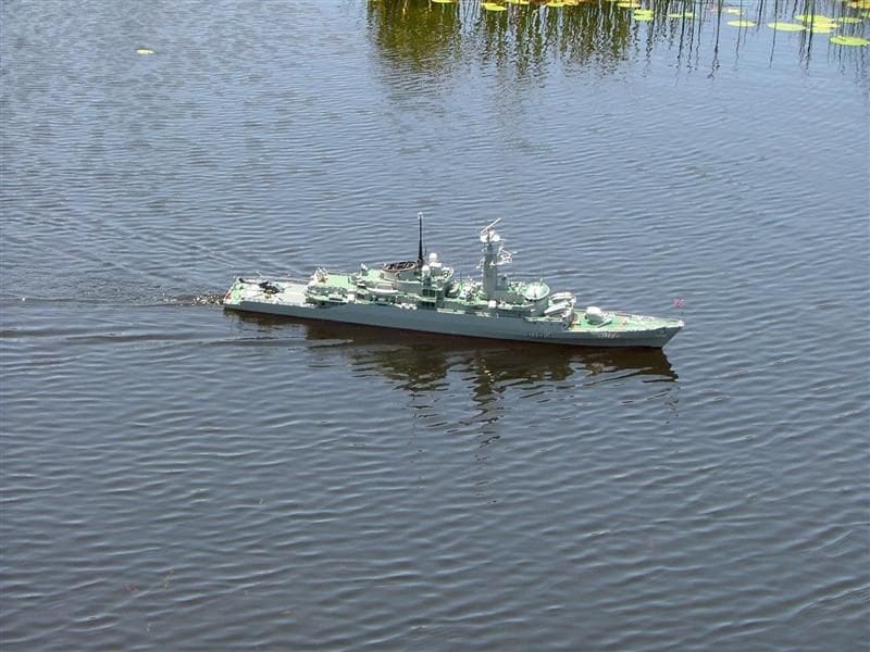
Attention could now be given to installing the running gear and rudders. APS supplied an excellent set of brass propellers, A frames, stainless steel shafts, stuffing tubes, connecting collars and universal joints for the drive train as well as the rudders. Once these were all installed, preliminary flotation tests were carried out. The model seemed to sit slightly above the waterline, temporarily indicated with a marker pen and electrical tape. Two 10Ah 6v SLA batteries were laid flat and low along the bottom of the hull as I planned to run the model off a 12v system by wiring the batteries in series with independent motor speed controls. The initial floatation tests were good, with the model being very stable and quick to right herself when healed her over deliberately at an extreme angle. I marked up where the batteries lay in the hull and fixed in place a set of battery holders that I made from aluminium right angled rod.
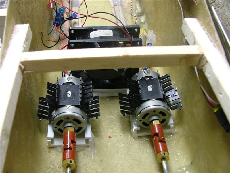
With all the running gear and batteries in place I turned now to the motors. The Type 21 was no slouch on speed and I was determined to get this right for this model. Michael Brown at Task Force 72 kindly evaluated some motor and propeller combinations and the Mabuchi 555 on 12 volts was the motor that showed the most promise. With the radio gear loosely installed in the model, I ventured out for a test run on Manly Dam which is my local freshwater waterway. The results were very good, producing a great turn of speed and positive response from the motors.
Taking the model back to the test tank we tethered the model against the sides of the tank and ran her at full speed for 30 minutes. Five amps was drawn for both motors combined (i.e. just 2.5 amps each). However, the motors were extremely hot to touch at the end of the test.
What was required was a cooling source, so I fitted to each motor, two r/c car motor heat sinks and a cooling fan in front of them. In addition, I fitted a single 12v 90mm computer cooling fan over them. Repeating the test again, with the motors running flat out for 30 minutes, resulted in a maximum of 2.3 amps drawn by each motor, but more important that were only mildly warm as against being painfully hot to the touch previously.
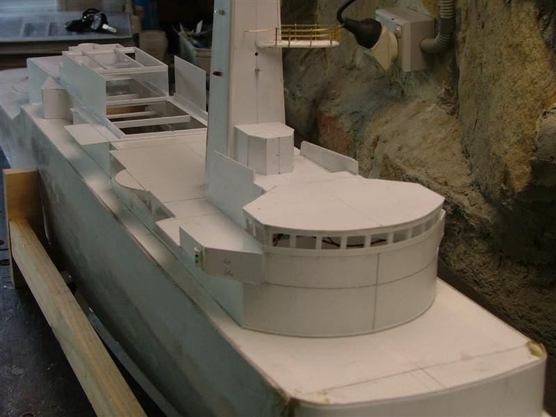
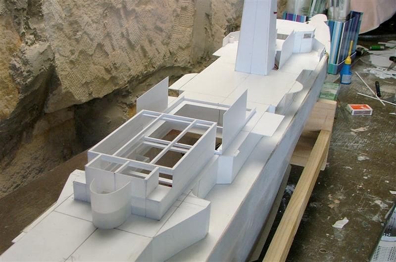
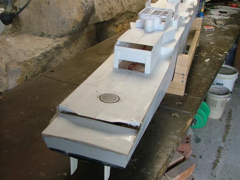
Superstructure and decks
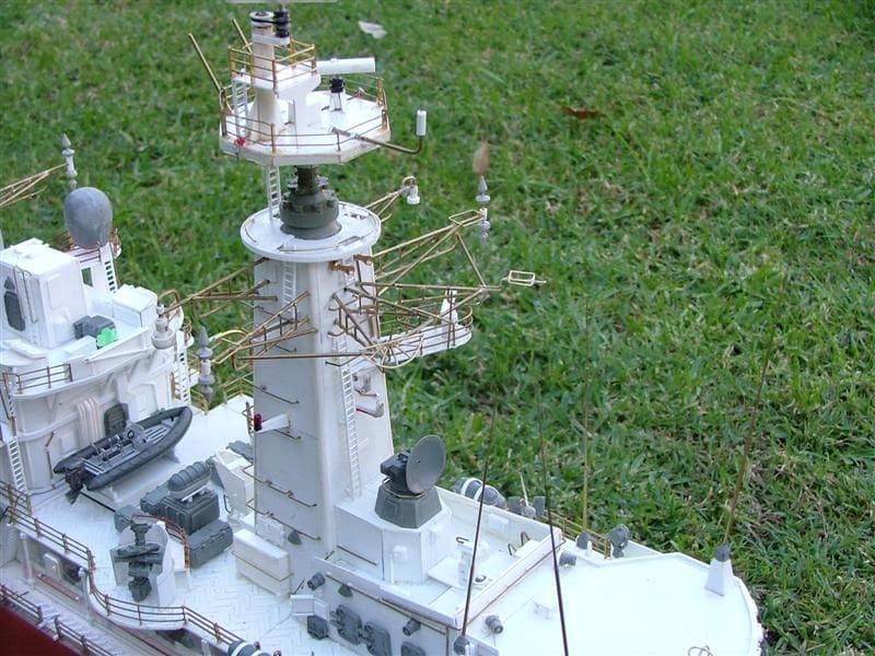
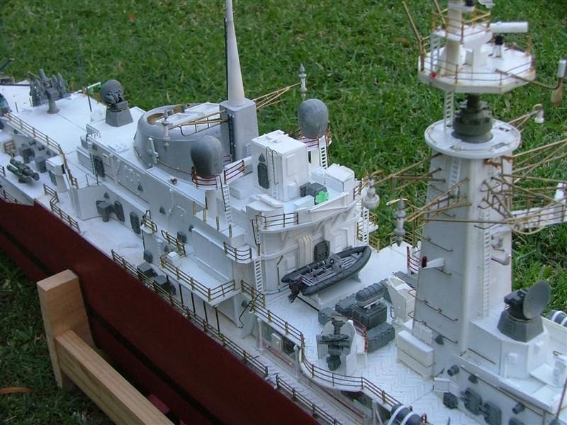
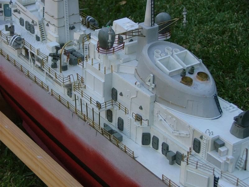
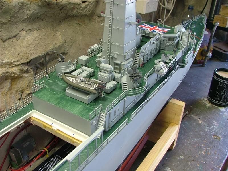
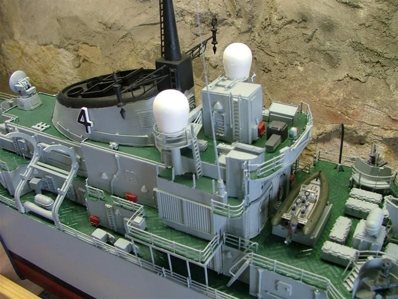
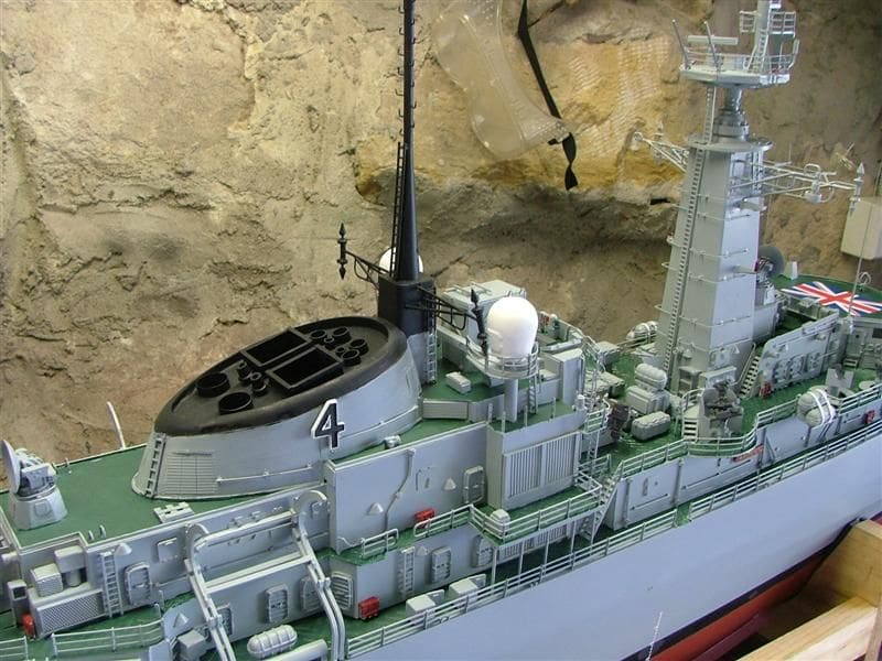
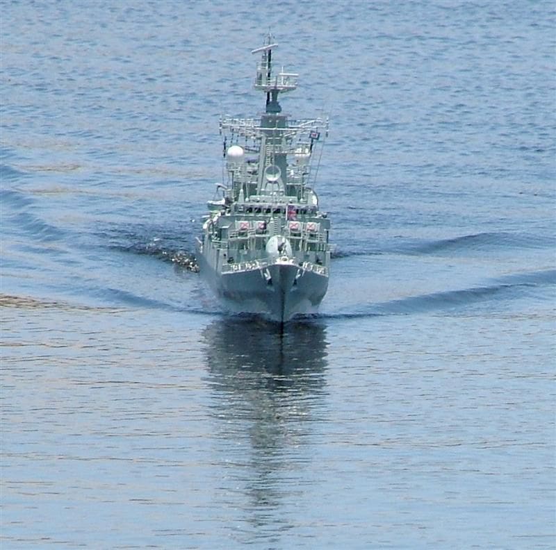
The key to keeping the weight down and improving stability, apart from ensuring all machinery and batteries were kept as low as possible, was that the upper parts had to be as light as possible. However, I still wanted to build maximum strength into the superstructure and include all the scale detail. I also needed the best possible access into the hull for the batteries and any maintenance required. The entire superstructure, save for a few detail parts, is constructed from styrene card. Most parts of the superstructure are just 0.5mm thick and so I employed a space frame type of construction method to include maximum strength and by so doing this allowed me to keeping the bulk of the weight, which is the outer skin of the superstructure, very thin. The space frame concept is simply a series of supporting styrene beams that are fixed in both a longitudinal and cross sectional fashion so as to support the whole structure and its outer skin. The result is a dramatic saving in top weight compared to using heavier and thicker styrene and at the same time the structure, thanks to the space frame, is also very strong. The flight deck area was fitted with micro-LEDs during its construction.
The construction of the foremast was similar to that of the entire superstructure. That is to say it is also a styrene space frame with a thin 0.5mm thick styrene outer skin. Great care must be taken when drilling this outer skin so as to allow the various pieces of brass rod, LEDs, tiny light globes and fittings to be positioned. This thin skin can easily puncture if too much pressure is applied, so great care needed to be taken with this rather delicate and intricate work.
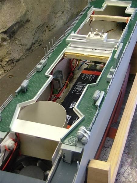
The superstructure was built in two sections so that when completely removed it allowed almost complete access to the entire inner hull. Even the floor of the hangar was designed to be removable, which on hot days allows an even greater airflow over the cooling fans for maximum ventilation. This is probably a strange concept to readers in the UK, but in Australia it is not uncommon to have a sailing day when the air temperature is well above 30 degrees C, which is hot!
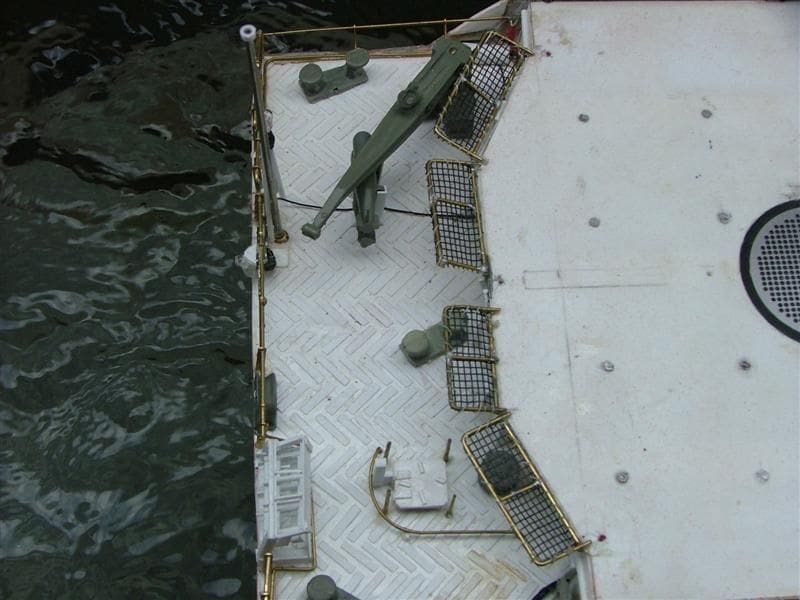
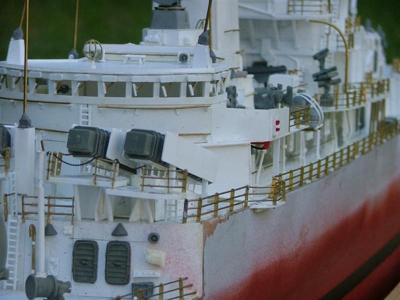
The entire superstructure sits on the deck located by coamings made from styrene strip. These strips, a minimum of 6mm high, run around the entire hull opening section and locate the superstructure positively. They also provide a barrier against water ingress, should the ship take greenies on my local lake when the wind speed rises above 15 knots.
A somewhat problematic decision, very early on in the construction, was that I would build the entire main deck out of styrene. On all the other models I have built, except my scratchbuilt 1/72 scale Italian aircraft carrier Giuseppe Garibaldi, the main decks have been of lightweight plywood, laminated with a thin coating of fibreglass resin. The choice with HMS Ardent to go the styrene route was primarily to save weight, but also as I needed a proper cement weld between the numerous styrene deck treads that were to be glued to it. The use of styrene for the main decks joined to a GRP hull is not without problems, as it has a much higher rate of expansion and contraction than the hull when experiencing extreme temperature variations. In a model with an ABS hull, this is less of a problem, as the hull has a similar rate of expansion and contraction to styrene. This too is the case for styrene decks and superstructure, the whole structure having exactly the same rate of expansion and contraction. So, provided a superstructure just sits and is not glued down onto a deck of another material, there is no problem.
When a main deck of styrene is glued onto a GRP hull, the difference in the behaviour of these materials is quite noticeable. The differing rate of expansion of the styrene to GRP can compromise the glued joint between the two materials and can result in the deck warping or cracking of the joint. There really is no perfect method of getting around the physical limitation of joining such unlike materials and then exposing them to such hot conditions as the Australian summer sun. This may not be an issue for people in cooler climates, but it is a very real factor for us model boaters here in Australia. What I did on the Type 21 to minimise the chance of warping or cracking of the decks, was to employ significant styrene underbracing both in longitudinal and cross sectional positions below the decks. These decks were then glued into position using 24 hour epoxy resin ensuring the decks were firmly fixed to the hulls longitudinal and cross-sectional timbers and braces.
Running the ship painted (which attracts more heat than unpainted white styrene which reflects heat) in the Australian sun, has resulted thus far in no visual warping. I do expect over time to have the odd crack appear at the deck edge joint between the GRP hull and the fixed deck areas. However, I must stress that in hindsight I will not be doing this again and will on my future projects use lightweight ply laminated with fibreglass resin for the main decks on a GRP hull. I think the reason why I have got away with using styrene main decks on this project was that in addition to the under deck bracing, the actual surface area under direct sunlight is not that large.
Working radars
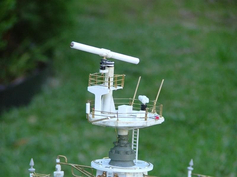
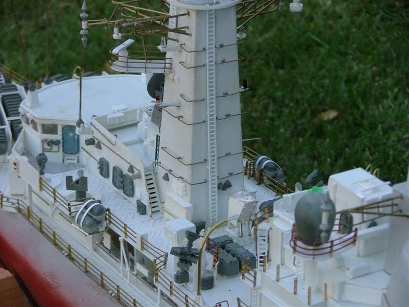
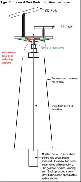
On all my model ships that I have built over the past 13 years, rotating radars are a nice function to include. In the case of the Type 21 this presented a unique challenge. On top of the foremast, there is a Type 992 radar and IFF (Identification Friend or Foe) radar. The Type 992 radar has air and surface searching/warning capabilities, and also serves as a target indicator. Both the radars rotate clockwise.
Soon into the build I realised that the method I normally use to drive a radar for scale speed rotation, is to strip a servo or micro-servo of its pot, add suppression to the motor and use the gears as a speed reduction device. However, this would not be possible on my model of HMS Ardent. There is not be enough space to model the radars accurately with the motors installed within, even with a couple of modified micro-servos. Moreover, I wanted the Type 992 radar to a have a self-balancing function just like the real ship.
So, I thought long and hard about a solution and finally had the idea of employing a centrally located shaft that would feed from a single modified servo in the main superstructure body up to a gearbox contained within the radar platform. This was quite a difficult engineering conundrum as amongst other things, with the very lightweight construction of the forward mast it was essential to ensure that the bearings were in perfect alignment. Early on I had a slight misalignment that given the considerable torque generated by the servo motor, caused the whole foremast platform to twist. This resulted in it being necessary to completely rebuild the mast and re-align the bearings. In fact, it turned out that not only was the alignment of the central driving shaft crucial, but also the precise alignment of the servo motor unit connected to it. To facilitate this, the sides of the superstructure below the mast were initially modelled in clear styrene, so I could check the alignment by looking inside horizontally.
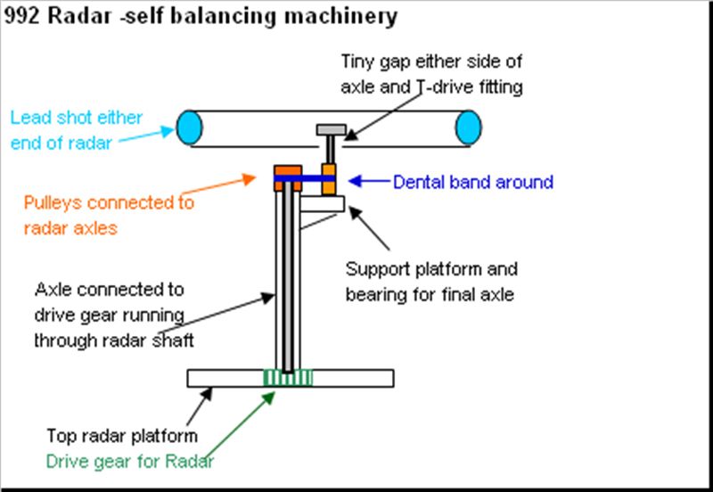
This particular layout allowed both radars to turn in the same direction and allowed an independent linkage to the Type 992 radar so as to allow a drive train to link to the self-levelling or gyro balance of the actual scanner. Running from two NiMH cells (2.4v total) both radars turn clockwise together. The smaller IFF turns at a slightly faster rate than the larger 992 self-balancing radar (just like on the real ship). The different speed is possible through the final drive to the self-balancing system of the Type 992 scanner. Even though the gear ratio to both radars from the single shaft is identical, the final drive via a pulley system using a small dental elastic band creates a slightly different rotational speed. Again, the key to this rather complicated arrangement was to ensure all the various bearings were installed correctly with no misalignment to cause shaft binding.
Complicating the functionality of the upper platforms are the navigational lights, yardarms and antennae arrays that were constructed from sections soldered from brass rod.
The funnel
One of the facts that I found odd about the Type 21 semi-kit, was that when I ordered it, no funnel was available. So as I wrote earlier, I set about making no less that eight prototypes before I finally achieved something that was about on the mark. I sent this to Allan Pew who put the original master I had made through a series of additional processes to produce the detailed, lightweight GRP version that is now a standard feature in the package.
Electricals
The model uses a 12 volt power system for the main drive motors and the JCC Electronics gas turbine sound generator. Sadly the latter is no longer on sale, but good alternatives are starting to appear in the market place. The model is fitted throughout with navigational lights (both miniature bulbs and LEDs). The LEDs require 2.4 volts, but the bulbs only need 1.2 volts.
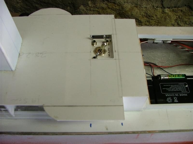
A centrally located switch box is positioned amidships just aft of the foremast and on the starboard side below the RIB stand. The switch panel is therefore hidden underneath the boat and its stand.
Transporting the model
One thing with which I am becoming more streetwise, is to plan construction around transport logistics. HMS Ardent is transported in a secure Thule Atlantis 900 car roof box secured to a roof rack. The use of roof boxes in my opinion provides a great deal of flexibility, particularly with the modern lockable types, such as my Thule, it being simply switched from one vehicle to another in a few minutes and the only pre-requisite is that the vehicle has a standard type of roof rack. This means whatever future vehicle you have, and as long as you have a roof rack, you will have the means to transport your models. The current roof box that I have is extremely large, holding a 2.17m long model cruise ship that I now have under construction. Needless to say, it could accommodate a number of models like HMS Ardent.
The height of the model means that the foremast section cannot remain on the model when it is stored in the roof box. The foremast itself could not be a single removable item, given the electronics and drive system for the radars, so I ended up having the two removable superstructure sections as described earlier. The forward part consists of the foremast and bridge area, and the second part is all the rest. This arrangement means the forward superstructure can be carried in a small padded box in the car and the after part can remain on the model within the roof box.
The Type 21 frigate has a large number of intricate and delicate antennae, as do many warships. All of these I designed to be removable together with the mainmast. This means there is less chance of breaking these features when working on the model. Mostly they either plug into their bases or swivel as indeed they would on the real ship.
The substantial electrical requirements of the features within the foremast and forward superstructure means using a bungee snap connector which is a bit like a Tamiya plug, but in this case with nine pins rather than just two. This is used to connect the electrical devices on the foremast and wheelhouse with the On/Off switches and power supply in the lower hull.
Conclusion
In summary, the APS Type 21 semi-kit is a really gem. The scale of 1/72 allows many scale features to be included on the model and the quality of the fittings is fantastic. You will still need a fair amount of scratch building skill to build the key features like the fore and main masts plus the lattice assemblies of yardarms and antennas, but having said that, the model was exceptionally enjoyable to build and after all that is what our hobby is about.
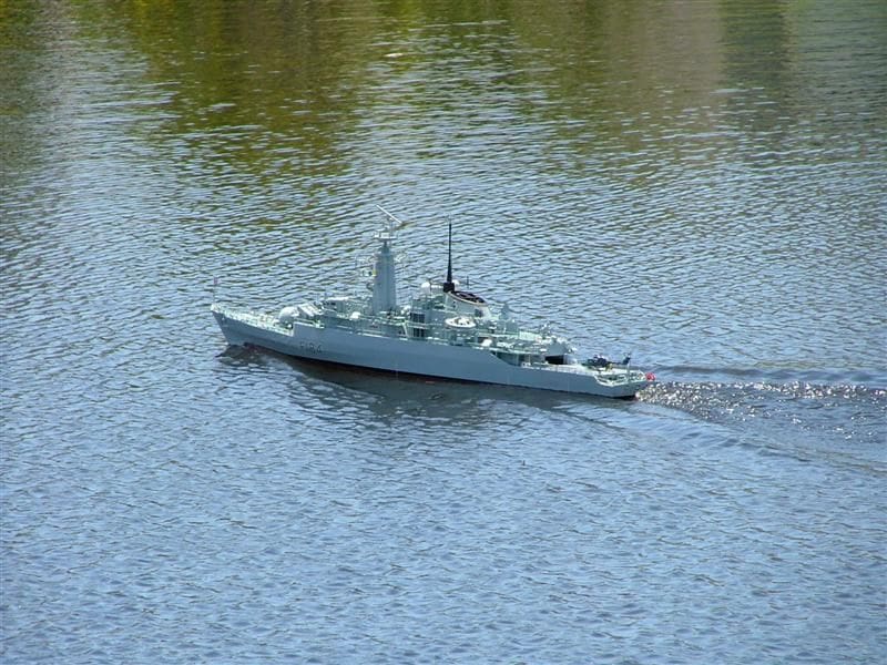
HMS Ardent is powered by two Mabuchi 555 motors with cooling heat sinks as well as fans for cooling. It has two Electronize FR15 type speed controls for independent throttle control and I use a Robbe F14 Navy twin stick radio, that has proved to be eminently suitable for this model.
The motors drive the model at an exciting scale speed, creating a nice impressive bow wave that is generated even at moderate speeds and the wake looks mightily impressive as well.
The 1/72 scale Type 21 is 1630mm (64.2ins) long by 170mm (6.5ins) beam. APS models does not have a website, but Allan Pew can be contacted by e-mail at: [email protected].
The author
John Slater works as an economist. He is a member of Task Force 72 (the Australian 1/72 scale model warship association) and has been building and operating radio controlled ships and submarines, both kits and scratchbuilt since 1996. He is currently the Editor of Course 0720, the official members magazine of Task Force 72 (www.taskforce72.org) and all his models are built exclusively to 1/72 scale and indeed some are now in the hands of private collectors and museums Editor.

