DAVE MILBOURN explains it all with a useful motor application table as a bonus! (see foot of article)
First, a couple of definitions: According to my dictionary, electronics is the technology of electrical circuits which involve active electrical components such as transistors, diodes and integrated circuits. It is distinct from electrical technology which deals with the generation, distribution, switching and conversion of electrical energy into other forms (e.g. light and motion) using wires, motors, generators, batteries, switches, relays, transformers, resistors and other passive components.
Now read that again, slowly please. It says, in other words, that electronics is the knowledge of how individual components work and how to assemble them together to make a working device, while electrical technology is the knowledge of how to connect together different devices to turn electrical energy into useful stuff like heat, light and motion. When applied to model boats this means that anyone with a basic knowledge of what I call ‘bells, batteries and switches’ can install the necessary electric circuitry to make the model do what he (or she) wants it to do without having to understand how the clever electronic bits in that circuit actually work. I’ve been challenged by the Editor of this magazine to write an article to illustrate and explain model boat electrics for the non-technical reader, so I hope what follows is at least halfway towards that goal. There will be a few slightly technical bits here and there but no complicated mathematics will be used! You can treat this article as a reference work, that is to say, diving into it for the bits of information you need, or sit down and read through the whole thing just so that you know what’s in there for when you might need it later.
Enjoy more Model Boats Magazine reading in the monthly magazine.
Click here to subscribe & save.
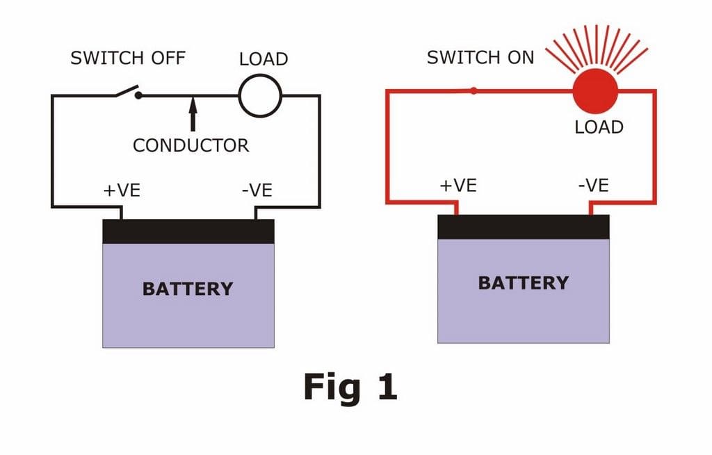
The very simplest electrical circuit involves a power supply, conductive wiring, a load and a switch. The circuit is dead until the switch is moved, at which stage a current of electricity flows through the wiring of the circuit and energises the load. The load does whatever it does for as long as the power is supplied and can be anything which consumes electrical energy such as a bulb, a sound unit or a motor. When the switch is returned to its original position the circuit becomes dead again and the load stops whatever it was doing. Simple enough so far? Good, then please see Figure 1. So let’s now deal with the elements of this circuit, one at a time.
Battery
This is the power source and is essentially a store of electrical energy. It has two poles, or terminals, which are termed negative and positive. The battery has chemicals inside it which react to produce little particles of electrical charge called ‘free electrons’ and shove them all up at the negative pole. This is insulated internally from the positive pole, which has a deficiency of electrons and whose sole function in life is to grab them from the other end of the battery. If a metallic conductor is connected between the two poles then the electrons will flow along it from negative to positive. The conductor is usually in the form of a thin metallic rod called a wire, or a bundle of very thin rods called a cable. The flow of electrons is called a current**.
Strictly speaking, a battery consists only of one cell, which has just one pair of positive and negative poles. For most uses this is impractical as the voltage of a single cell is only between 1.2v and 3.7v, depending on the type of battery, so most model batteries are actually packs of cells which are either welded/soldered together in a chain or manufactured together inside the same case. A pack will therefore contain several individual cells, but only one overall pair of positive and negative terminals, i.e. the positive of the first cell in the chain and the negative of the last one. For the purposes of this article I will use the terms ‘battery’ and ‘pack’ as if they mean the same thing.
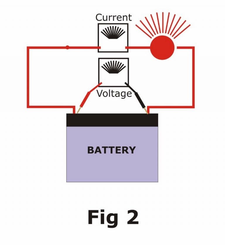
Any battery is identified by two very important properties. Its voltage puts a value on the electrical ‘pressure’ it exerts between the negative and positive poles, i.e. the higher the voltage then the more electrical pressure it can exert on a load. Increasing the voltage will, for example, makes a bulb glow brighter or a motor turn faster. The battery also has a capacity, which is a measure of how much electrical energy it holds and can supply before it becomes discharged, or ‘flat’. The rate of flow of electrical current along the conductor is measured in Amps; the more amps which a load draws from the battery then the quicker it will discharge. The value of a battery’s capacity is the arithmetical product of the current and the time for which it can be supplied and is quoted in Amp-Hours (AH), or Milliamp-Hours (mAH) which are 1000 times smaller. A battery which can supply one amp for one hour has a capacity of one amp-hour. To give a figure more typical of a model boat application, a 7.5AH battery will supply a current of 2.5 Amps for 3 hours (2.5 x 3 = 7.5). Note that this does not depend upon the voltage of the battery which, as I hope you have learned, is a different thing altogether, Figure 2.
There is an arithmetical relationship between voltage and current in a circuit and it’s called Ohm’s Law and states that the voltage across a load divided by the current flowing through it is called its resistance, or R=V/I, where I is the usual symbol for current. For most practical purposes you won’t really need Ohm’s Law but it’s useful to be aware that it exists, if only to know what ‘resistance’ means. For model use there are two types of battery:
Dry batteries, which are not rechargeable and useful really only for low-current applications such as the transmitter
Rechargeable batteries, which we tend to use for everything else. Rechargeable batteries come in various different guises and to describe each fully would take a lot of space and probably bore you rigid. The main types used are Sealed Lead-Acid (SLA), Nickel-Metal Hydride (NiMH) and Lithium Polymer (LiPo). Their names refer to the chemicals inside them (electrolytes) which react to generate the electrical energy, and each type has its use in model boats. Nickel-Cadmium types (NiCad’s or NiCd’s) were popular at one time but have been removed from the market because of the adverse effect on the environment of discarded heavy-metals such as cadmium.
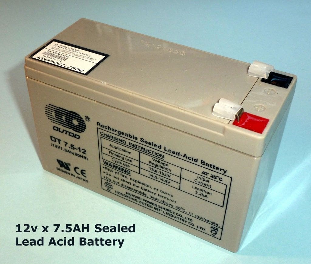
SLA batteries are heavy, the ‘L’ stands for lead after all, and cannot generate very high currents, so are used where slower motors are appropriate, and where they can contribute usefully to the total weight of ballast required to get the model down to its scale waterline, e.g. in tugs. The usual sizes for SLA batteries are 6v and 12v, both in many different capacities, although there are also some 2v cells around these days, Photo 1.
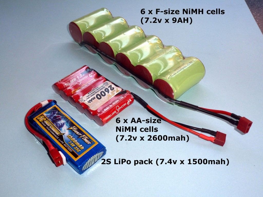
Nickel Metal-Hydride (NiMH) batteries are generally made up in packs of joined-up cells, each cell having a nominal voltage of 1.2 volts and the cells coming in different case sizes. The smaller case sizes have the smallest capacity; typically around 850mAH for an AAA pack, while the largest cells, ‘F’ size, go up to 10000 mAH (or 10AH). Packs of these cells are much lighter than their equivalent capacity SLA types and thus suitable for faster models where low weight is more important. NiMH cells can supply a lot more current than SLA batteries and can also be fast-charged at the lakeside from a portable charger. The term ‘nominal voltage’ is used to indicate the voltage at which the pack will discharge for the majority of its discharge cycle. When fully charged, a NiMH cell can have as much as 1.55 volts across the poles. This will quickly settle down to about 1.2v and stay at that level until it is almost fully discharged. At that time the voltage starts to drop quickly and should not be allowed to go below 1v per cell or damage will occur.
Finally, Lithium Polymer (LiPo) batteries are the newest kids on the block and are lighter and more powerful even than NiMH cells. Their nominal voltage is 3.7v per cell, BUT they do have to be carefully handled and monitored. Careless handling or overcharging/discharging can in the extreme case, cause them to catch fire and even destroy your model. For this reason it’s always advisable to use a speed controller which will monitor the battery voltage and cut off the power to the motor before it reaches a critically low value, e.g. the Mtroniks Tio range. You can also obtain a stand-alone device to do this, or a simple monitor which just sounds an alarm when the value is reached. That said, LiPo batteries are in use all over the world and instances of such accidents are becoming rare. As regards charging, if you purchase the correct type of balancing charger and follow the instructions, then you will have no problems. LiPo packs come in multiples of 3.7v and are quoted in the form ‘XS’ where X is the number of cells. Thus a ‘3S’ pack is 3 x 3.7 = 11.1 volts. The capacity is quoted in the usual way i.e. mAH, and the maximum current which can safely be delivered is given in the form ‘YC’, where Y is the value of the capacity (confusingly in Amp-Hours). As an example, a 1700 mAH LiPo pack has a corresponding ‘C’ value of 1.7 and so a pack rated at 20C can supply a maximum of 20 x 1.7 Amps = 34 Amps, Photo 2.
The only other thing which I should emphasise about any type of rechargeable battery is to use the correct type of charger and always follow the charging instructions.
**Please note that unfortunately for some reason the ‘conventional current’ flow in circuit diagrams is always labelled as being from positive to negative, but it’s not important as long as you remember to connect the terminal or wire of any load which is marked with a + sign to the positive terminal of the battery etc.
Polarity
As described just now, there is a flow of electric current when a load is connected between the two poles of a battery. Unfortunately some loads are sensitive to which way around they are connected (polarised) while others aren’t. Examples of non-polarised loads are conventional bulbs, relay and switch terminals and fuses. Practically any unit which includes semiconductors (transistors, PIC chips etc.) will be polarised, so make sure that you connect items such as speed controllers, sound units and receivers the right way around. They are usually marked with + (positive) and – (negative) signs/labels or at least the instructions will tell you how to connect them. Yes, it DOES matter! If you connect up a polarity-sensitive device the wrong way round, even for a split second, then you will probably damage it and often fatally. Those of us who have suffered this fate often then refer to ‘The Magic Grey Smoke’……………!
Conductors
For our purposes, this means wiring and usually of the insulated flexible variety, so that complicated circuits can be accommodated inside complicated hull shapes with lots of bulkheads and electronic gizmos to negotiate.
A wire, or cable, is made up of a central conductive core, usually multiple strands of thin copper wire, and an insulating outer sleeve. The sleeve is typically either PVC or a silicone-based compound, which is more flexible and resistant to heat. The most crucial factor as far as wiring is concerned is to use the right thickness/diameter. Too high a current passing through a cable will increase its temperature to the point where the insulation breaks down and melts and the conductor inside can short out against other ‘live’ components. Fires have been caused by burning insulation, too. Model boat circuits come basically in two types; those which include motors and those which don’t. The former will be subject to high currents while the latter will only carry a few amps at most. My own preference is to use thick multi-strand silicone-coated cable for power wiring, and thinner multi-strand PVC ‘hook-up’ wire for such items as sound units and lighting. The gauge of the silicone stuff is usually quoted in AWG (American Wire Gauge) and the following table will be useful when working out what gauge of wire you need:
AWG Conductor dia.(mm) Max current (Amps)
10 2.59 55
12 2.05 41
14 1.63 32
16 1.29 22
18 1.02 16
20 0.81 11
22 0.66 7
For other wiring I find that PVC insulated hook-up wire of 7 strands of 0.2mm dia. Conductor, usually termed 7/0.2, is okay up to 2 Amps while 10/0.1 is good for low-current lighting circuits. If you need very thin cable then I suggest buying multi-core alarm cable which contains 4, 6 or 8 different coloured insulated multi-stranded cables inside one outer sheath. Others have used telephone wire or enamelled copper wire, but you have to scrape off the enamel insulation on the latter type in order to make a decent joint.
Connectors
There are literally dozens of different types of electrical connectors, many of which you will find on model boat equipment. The pictures show the main types in use, with the exception of the familiar domestic electrical multiple screw terminal blocks, also known as ‘choc blocks’. These are fine for their original application, i.e. domestic wiring with single-core copper wire, but if even slightly over-tightened, the screws may secure only a few of the wires of a stranded conductor cable or even cut right through them. Avoid using these if at all possible. The golden rule is that if a manufacturer has fitted a particular type of connector to the wiring on his unit then you can assume it’s safe to use it, so fit the appropriate mate to the connecting cable and all should be well. Where no connector has been supplied, then you need to decide what type to use, Photos 3,4 & 5.
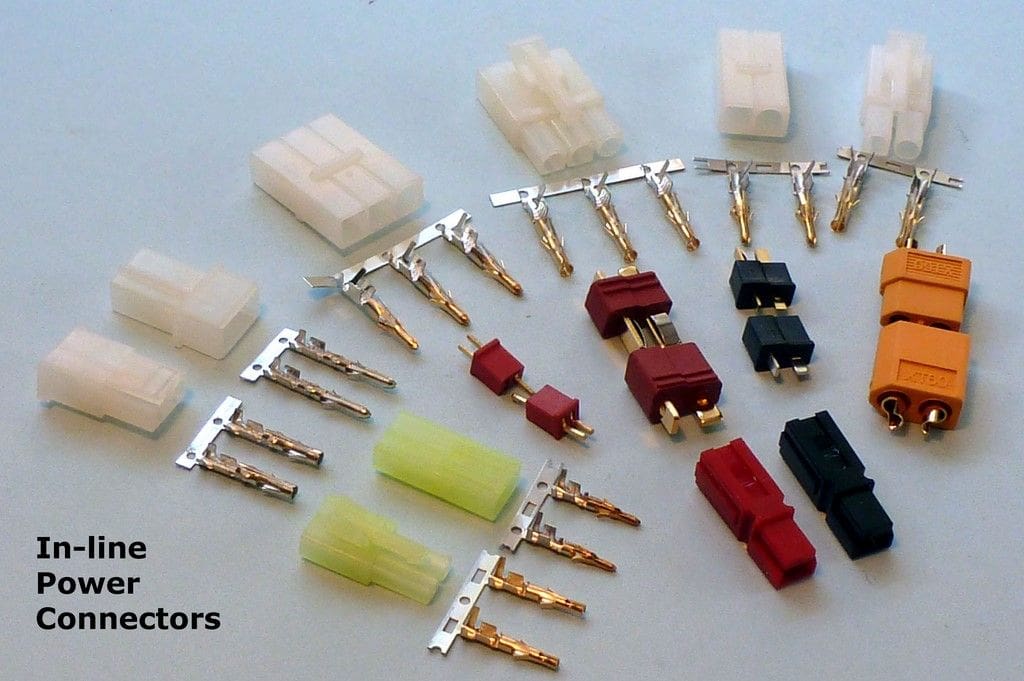
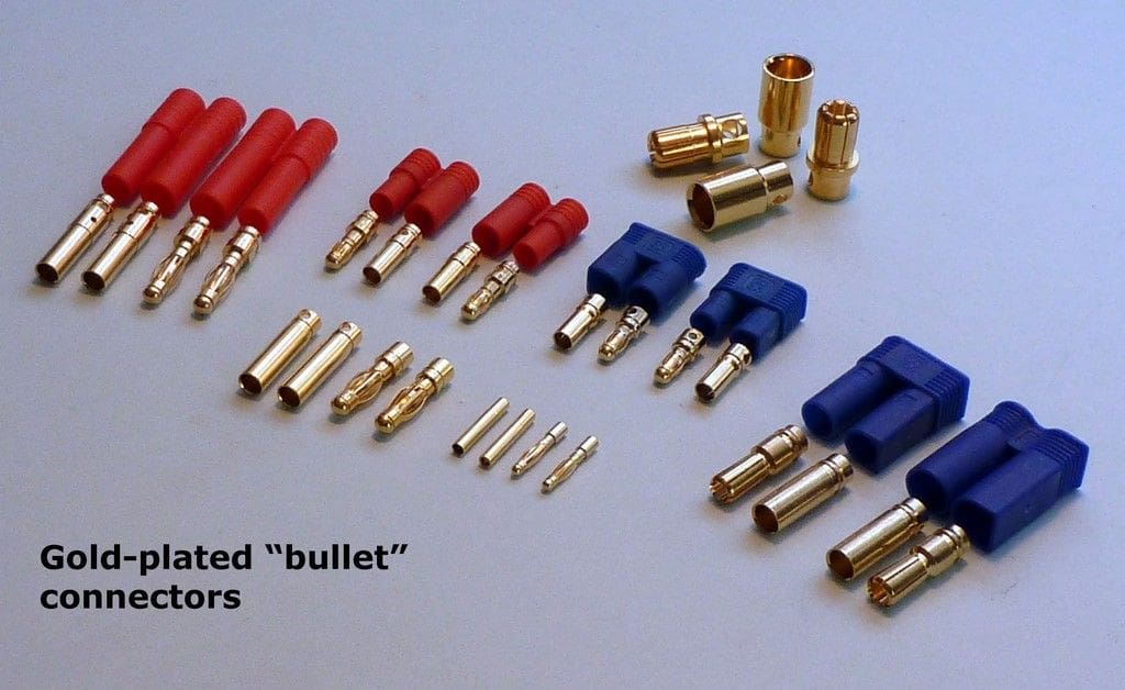
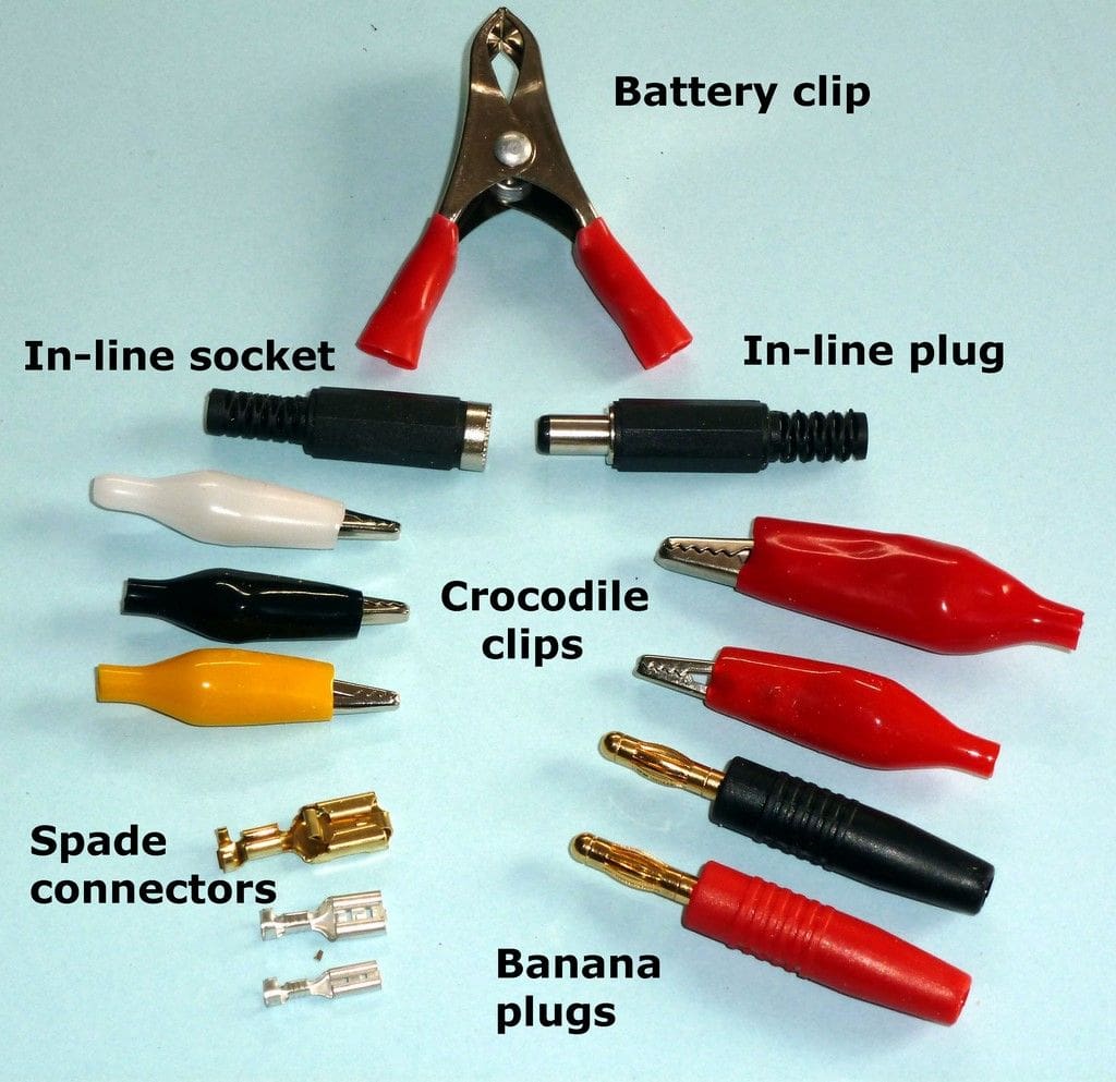
For general circuits of less than about 15A (15 Amps), the Tamiya types are very popular. For higher currents then consider the Deans type, or the gold-plated bullet connectors for very high currents. Do make sure that you fit insulation (usually heat-shrink tubing) over any soldered joints. Also make sure that you fit the shrouded sockets to the battery as this is to avoid un-insulated plug connections accidentally shorting together and blowing up the battery pack!
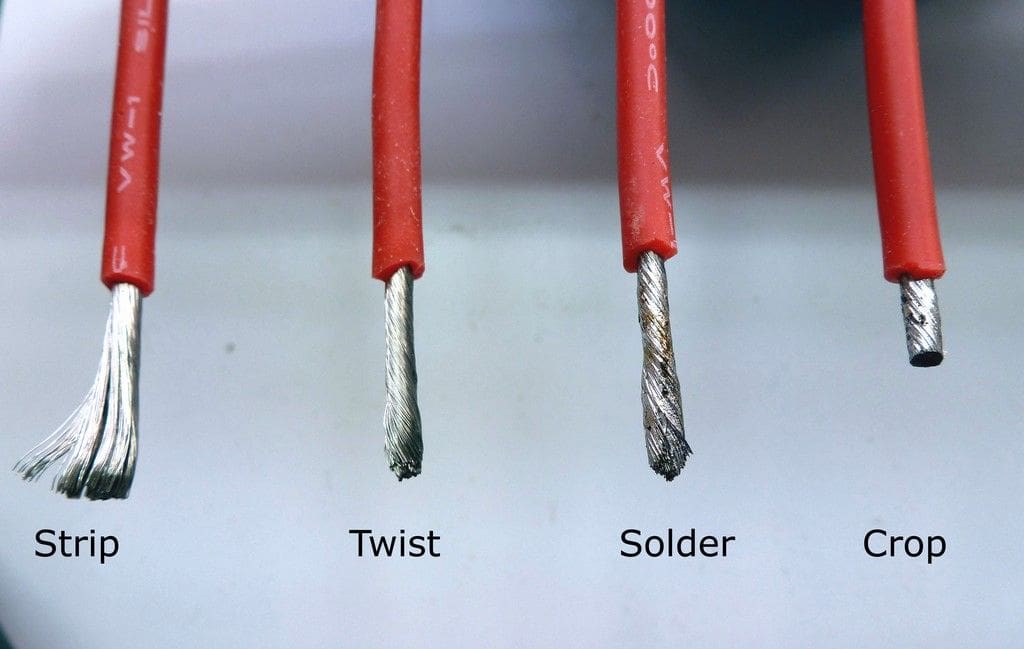
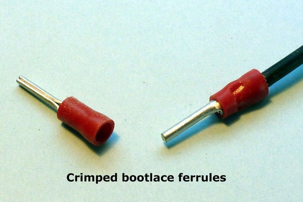
If your electronic units have screw terminals then you will need to prepare the ends of the cable to suit. NEVER just twist the strands of cable together and stuff them into the terminal. You will inevitably discover one day that there is a loose strand (or ‘whisker’) of wire which finds its way across to a neighbouring terminal, causes a short-circuit and melts or blows up something. At the very least you should strip, twist and tin the strands with solder, then crop them to length, Photo 6. Ideally plain cable ends should be terminated with a crimped bootlace ferrule; the blue and red colour-coded ones are the most useful sizes for models, Photo 7.
Soldering
This is the single most terrifying aspect to fitting out model boats with electrics, if my correspondence is anything to judge by. You wouldn’t believe the lengths to which some folk will go to avoid soldering, yet it’s very easy if you follow the rules and use the right tools and materials.
For general soldering use a 15 to 25 Watt mains voltage electric iron. Fancy little gas-powered torches are barely useful for any electrical soldering except field repairs, but they are excellent for browning crème brûlée! I don’t use one for anything electrical myself. For heavy-duty cable, i.e. anything thicker than 18AWG, a 40 to 80 Watt iron is better, especially if it has a decent-sized flat tip fitted (4.2mm or wider). I have used a soldering gun which heats up very quickly, but is too hot and cumbersome to use for most electrical work. Solder wire comes in two sizes; 18SWG and 22SWG. I prefer to use the thinner type for all joints, as you can feed it into a heated joint without the risk of flooding the joint with excess solder. Choose solder with a lead content, as it’s easier to use than lead-free, and a resin flux core. NEVER use an acidic flux for electrical soldering. The other major rules are:
1) Always make sure that the work is totally clean and degreased before you try to solder it.
2) Wherever possible, hold the two pieces to be joined together with non-ferrous clamps or similar before applying the iron.
3) Never carry solder to the joint on the iron tip.
4) Wipe away excess solder from the tip of the iron with a damp sponge regularly – never take a file to the tip of a soldering iron or you’ll destroy any special coating it may have.
5) Always scrub off any excess flux from the joint afterwards. Methylated Spirits or Isopropyl Alcohol are OK, but a proprietary aerosol circuit board cleaner such as Warton’s Total Clean 200 is best.
6) A good solder joint should be clean and shiny-bright. If it looks grey and dull then the chances are it’s what we call a ‘dry joint’ and will neither conduct electricity properly nor physically hold together for very long. If in any doubt remake the joint.
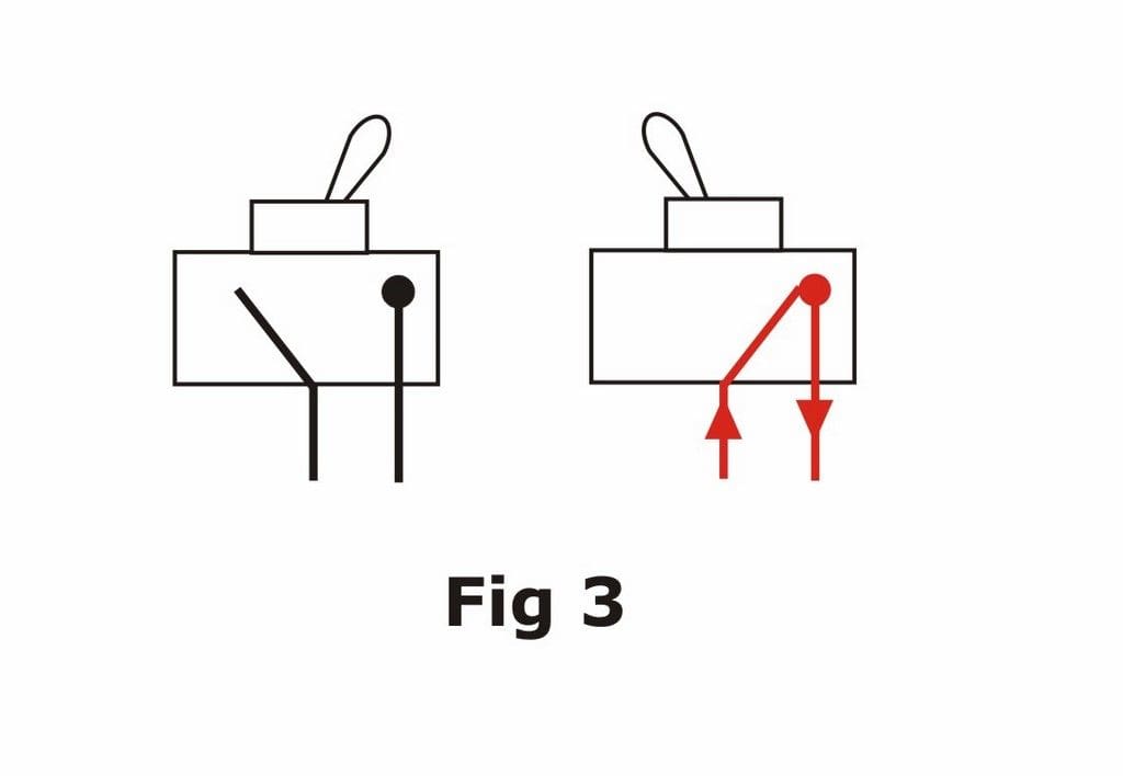
Switches
These are devices which are operated either manually or via remote control and are used to turn electrical circuits on and off. In its simplest form, a switch has a lever which moves a conducting piece of metal into a position where it makes contact with another fixed conductor, thus bridging the two and allowing an electrical current to flow between them. Each of these is called a terminal (or pole) and is connected to the wires within the circuit, thus controlling the current in that circuit, Figure 3.
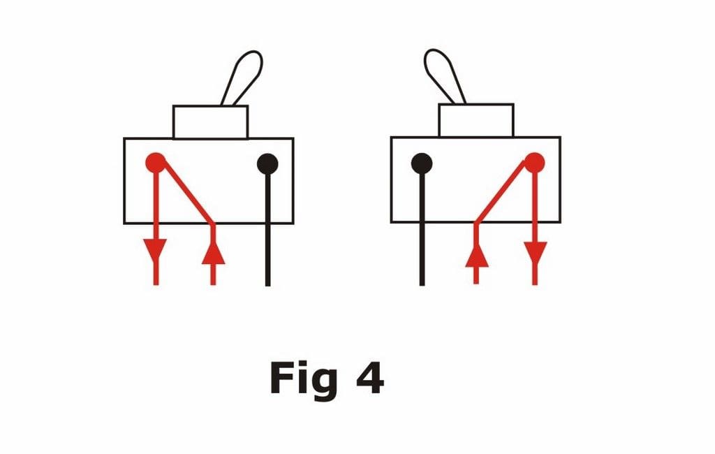
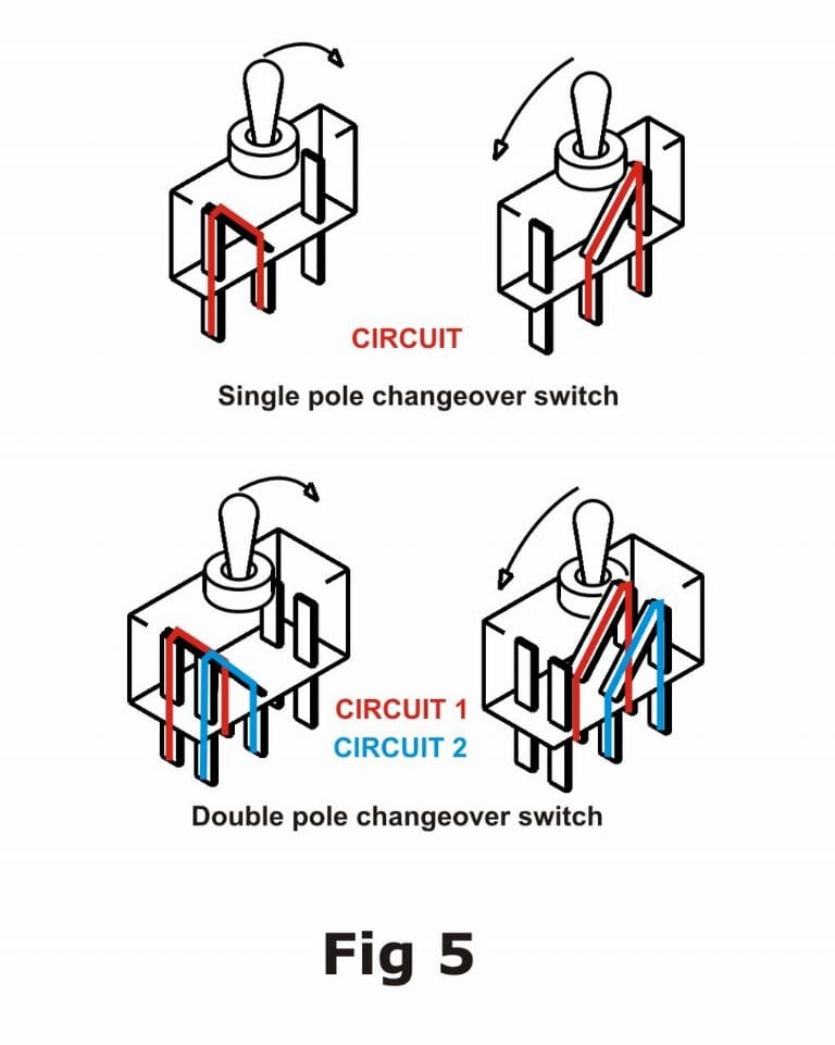
Manual switches are used in model boats to turn on and off the power from the batteries to the various loads. Usually these switches have an extra terminal, so that the moving contact is touching one or the other of two fixed terminals at any time. This can be used to divert the flow of current from one circuit into another and is called a changeover (or double-throw) switch, Figure 4. A simple switch which only has one set of terminals is called a single-pole switch, while a switch which can operate two independent circuits with just one toggle is called a double-pole switch, Figure 5. You will find switches referred to by their abbreviations SPDT and DPDT, which are respectively Single Pole Double Throw and Double Pole Double Throw. The centre contact of a set of three is always the common contact.
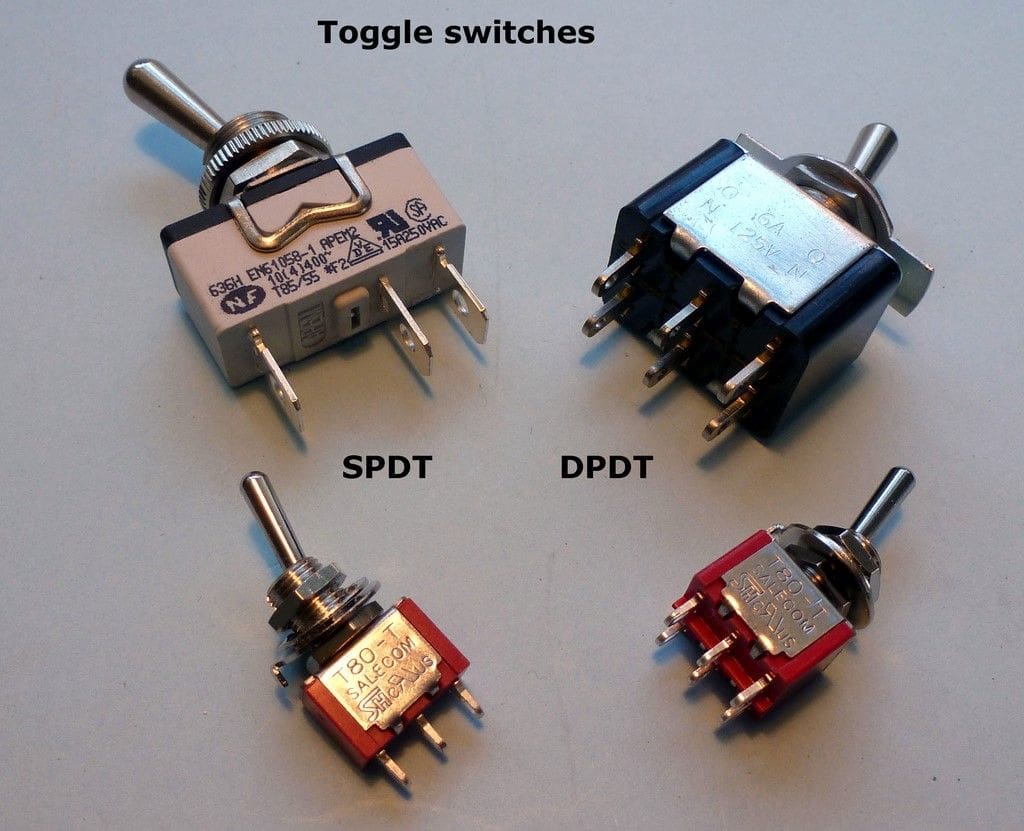
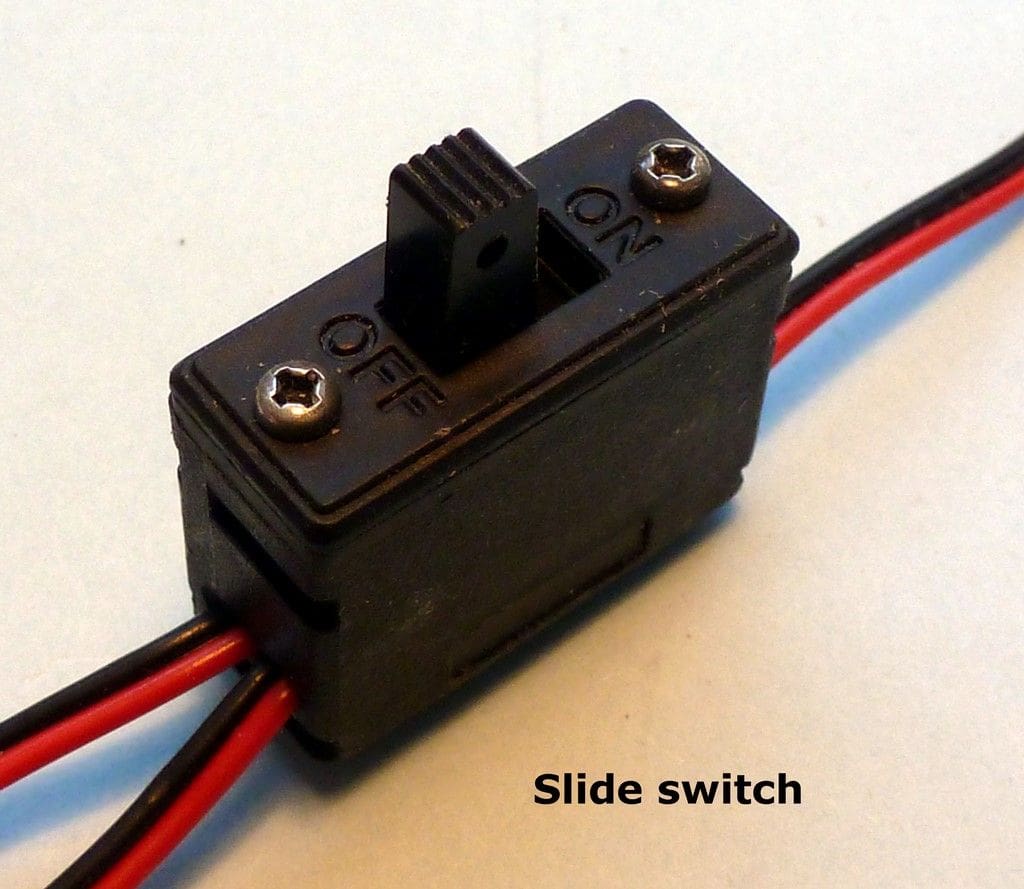
The choice of switch depends upon what you want it to do and also what current it will be conducting as switches are rated for voltage and current. I recommend a 16A toggle switch for motor circuits and either a 2A or 5A toggle switch for lower current circuits, Photo 8. Note that these ratings are for the ‘switching’ current at a mains voltage, i.e. the current which will flow instantly as soon as the switch is thrown. In practice they are capable of conducting a higher current once they are ‘on’. In nearly all cases in a model boat we are dealing with much lower voltages and there will be very little current flowing initially until you actually move a transmitter stick and energise something like a motor. I don’t personally use slide switches, but they are still fitted by radio manufacturers in the wiring harnesses which they supply to connect receivers to battery packs, Photo 9.
Switches being what they are, the toggle or slide needs to be accessible from outside the model. This means either leaving it standing proud but in a less visible place (e.g. inside an open cockpit); hiding it under a removable hatch, or modifying a deck feature so that it moves and operates the switch. For submarines none of these options are practical, so you might want to fit a magnetic switch. This is based on a magnetic reed switch and is mounted on the inside of the model, right up against the outer skin. To operate it, you simply ‘wipe’ a permanent magnet along the outside of the skin from front to back of the switch area. This energises the thin reed switch, trips a latching relay and makes the circuit. Alexander Engel KG sell two different types; one for models with a BEC (Battery Eliminator Circuit) speed controller and one for those without, each in either 6v or 12v versions They are however, as the Editor says, not exactly cheap, Photo 10.
Remotely-controlled switches do essentially the same job as manual ones, except that instead of moving the slider or toggle of the switch with your finger (or a magnet), you operate a control on the transmitter of your radio which sends a signal to a special sort of switch inside the model to turn on and off the particular load e.g. lights and more about these later.
Series versus Parallel Connection and Loads
At this point I will have to explain those confusing terms parallel and series. There are two very simple rules here.
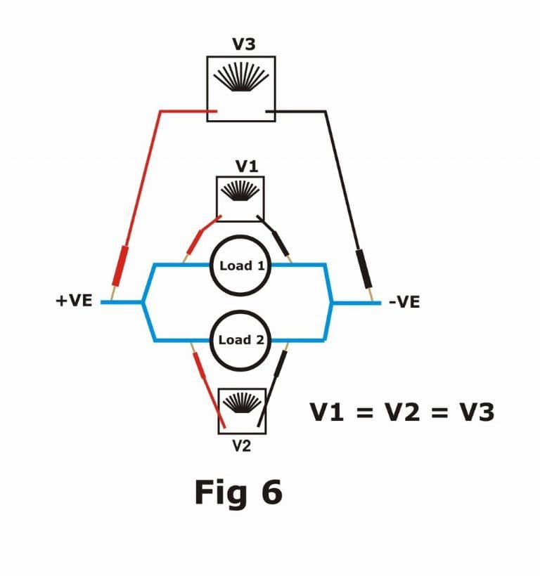
Loads connected ‘in parallel’ go alongside each other in side-by-side (parallel) cables which are then connected at each end, like two sidings along a single railway track. The voltage across each load will equal the total voltage across the circuit, Figure 6.
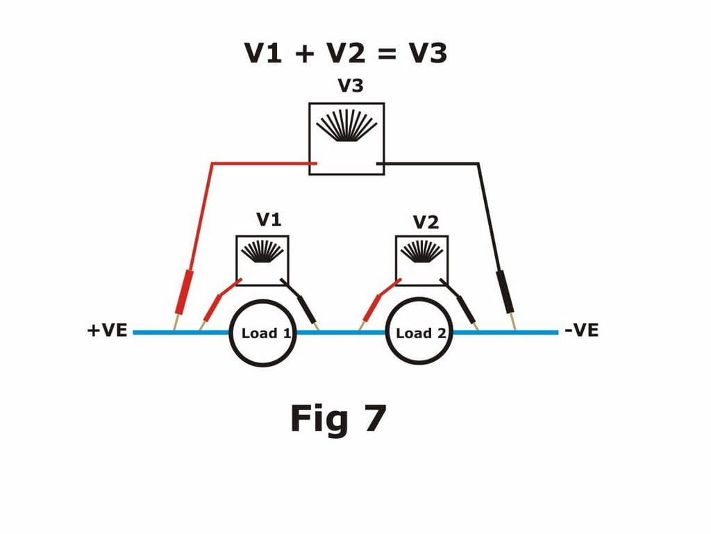
Loads connected ‘in series’ are connected one after the other along the same cable i.e. like a series of programmes on TV. The voltages across each load will add up to the total voltage across the circuit, Figure 7.
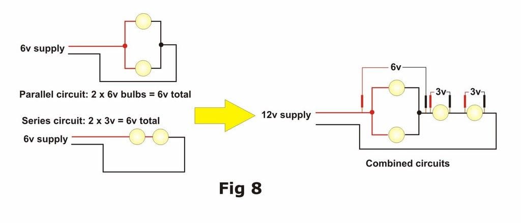
As I said earlier, a load can be anything which consumes electrical energy but typically will be a motor of some sort, or lights or a sound effect unit. You can fit such loads in series into a circuit where their total operating voltage equals that of the whole circuit. As an example; two 3 volt bulbs wired in series will require a total of 6 volts across the pair to operate them. This is a good way to combine bulbs of a different voltage, e.g. two 3 volt bulbs and a 6 volt bulb all in series adds up nicely to 12 volts. If you wire two 3v bulbs in parallel however, they will require only a 3v battery across the circuit as each will receive 3 volts. You can combine loads in circuits which involve both series and parallel wiring if you like. Please see the illustration of a typical lighting circuit in a modern tug model, Figure 8. Here the supply voltage is 12v and it’s supplying both a series circuit comprising of 2 x 3v bulbs and a parallel circuit of 2 x 6v bulbs. Note that if one of the bulbs in a series circuit fails then the whole circuit becomes dead, whereas a failed bulb in a parallel circuit has no effect on the other bulbs. You’ve quite likely already discovered this when hanging Christmas tree lights?
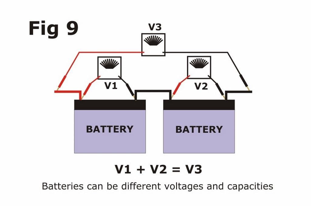
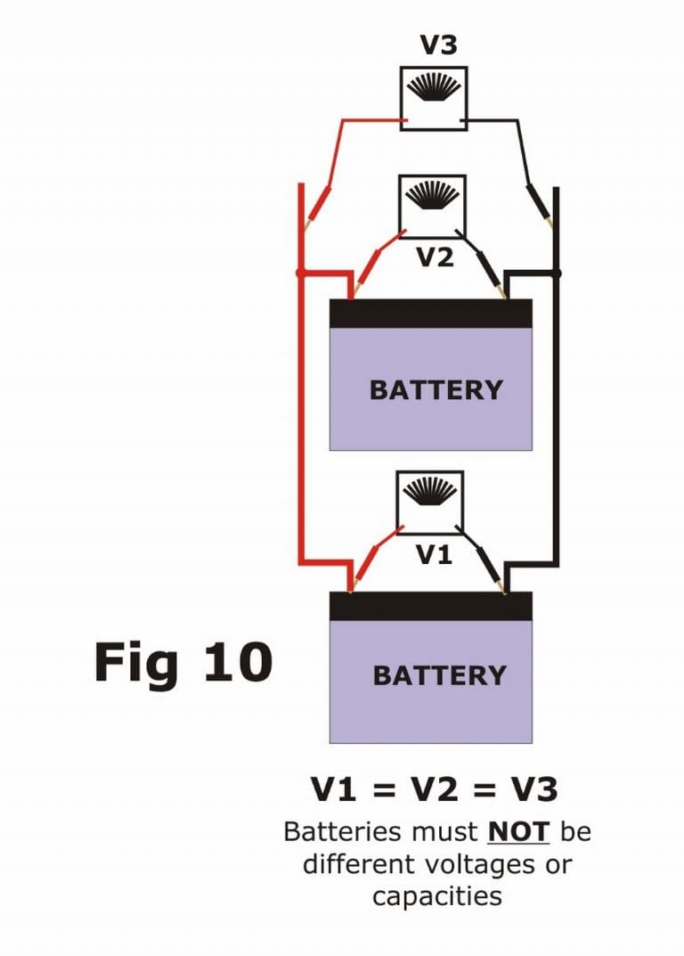
The terms ‘series’ and ‘parallel’ are also applied to connecting batteries, but beware! While you can connect two batteries with different voltages and capacities in series, you must NEVER connect two batteries of a different voltage in parallel or one will discharge into the other, with potentially serious damage to both batteries and possibly the model. As before, the total voltage of a series pair will be the total of the two battery voltages, Figure 9, while the voltage of a parallel pair will be the same as the two individual batteries, Figure 10. The capacity of a parallel pair will be twice that of the individual batteries. In practice you should always make sure that the two batteries in the pair are the same type (e.g. SLA or NiMH) and the same capacity (e.g. 7AH), irrespective of whether you are wiring them in series or parallel.
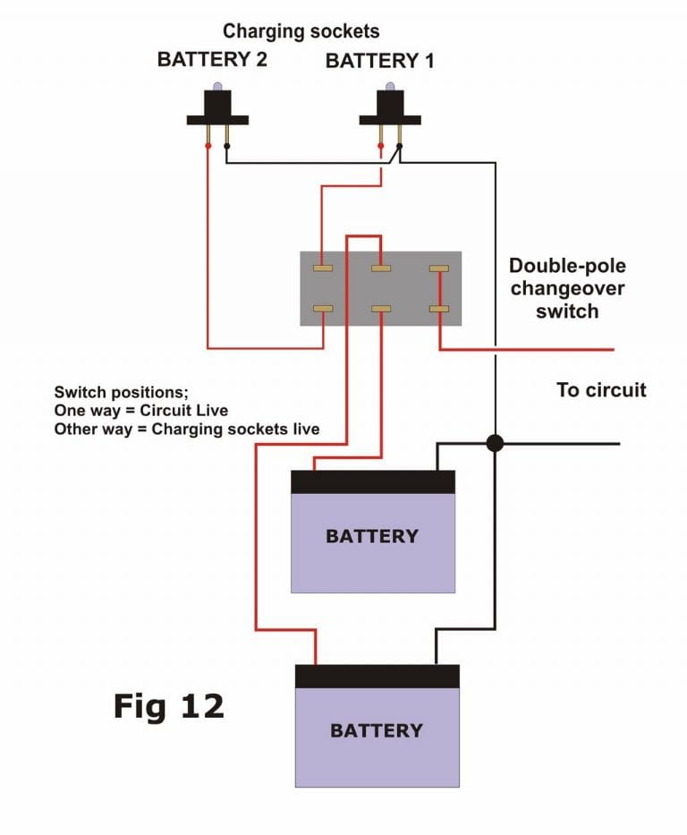
Ideally you should disconnect pairs of batteries from each other when charging and charge them separately as there’s always the risk that one will charge at a different rate and be the weaker of the two if you charge them together as a pair. If you can’t, or don’t want to remove them from the model, then you can use a double-pole changeover switch to connect them to charging sockets in the model. The connections for series and parallel connections are shown in the diagrams Figures 11 & 12 respectively. Note that the switch in the parallel set-up acts also as the On/Off switch for the whole circuit, while in the series circuit you need a separate On/Off switch (in the positive wire) to do that job.

Planning
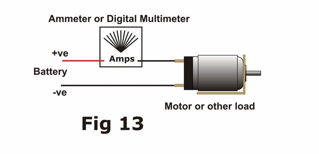
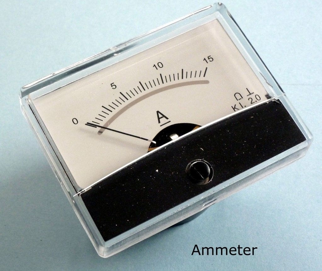
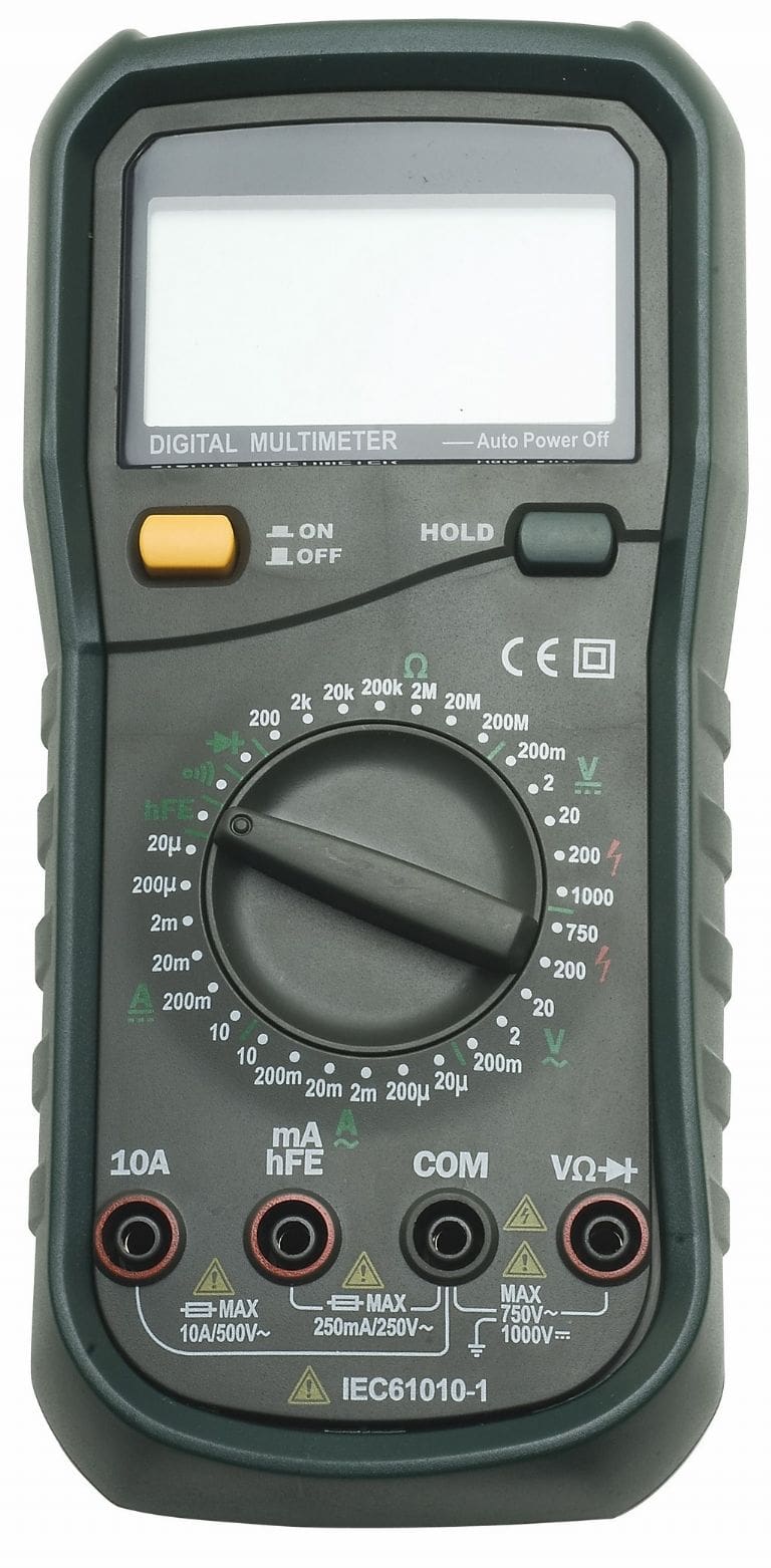
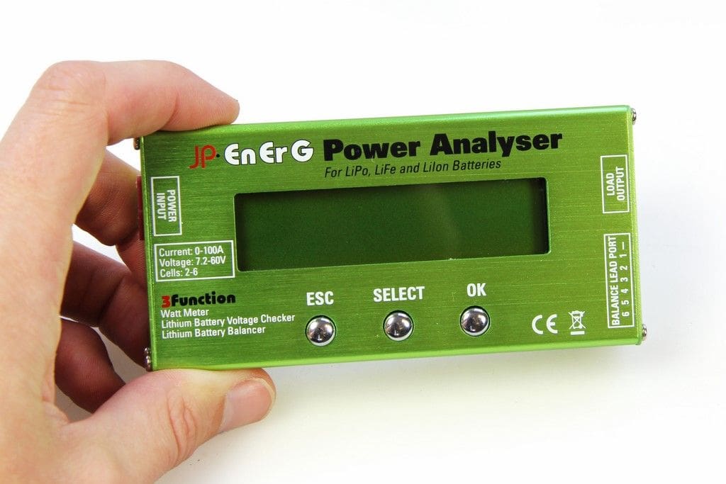
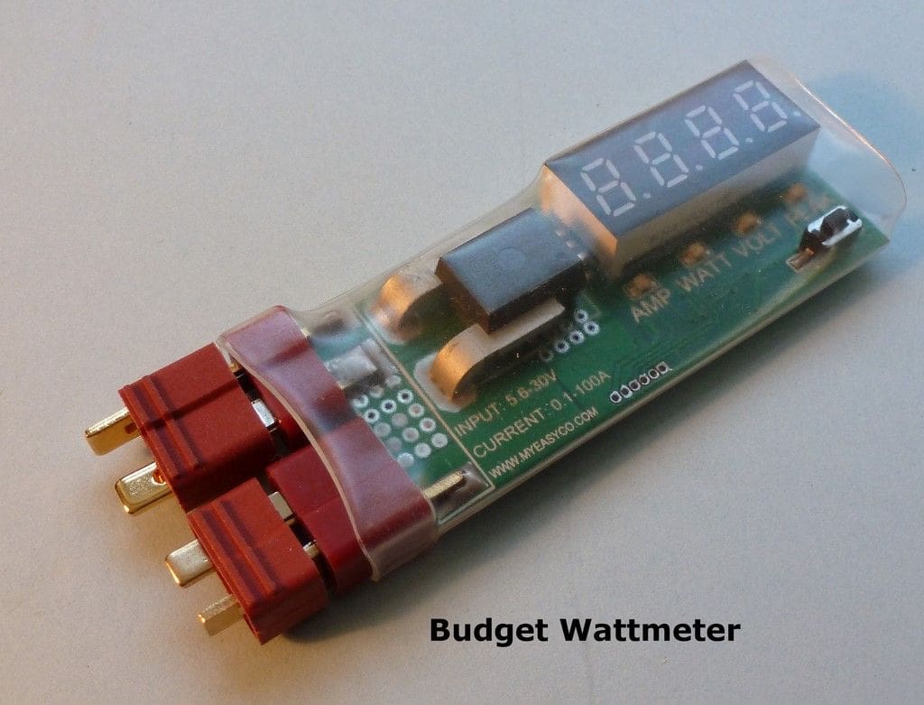
Before you can plan an installation you need to know the operating voltage and the approximate current drawn by each of the loads. The operating voltage is usually specified, e.g. a 12v motor, 3v bulbs etc., while the current is seldom mentioned. You can measure the current drawn by any load by connecting it to a battery of the correct voltage and connecting an ammeter in series with it, please see Figure 13. You need then to switch on the circuit and read off the current. For a motor you will need to simulate the load it will be working, so a main drive motor should be fitted into the model and running with its propeller in the water when you measure the current. Most digital multimeters have a scale which will read up to 10 Amps, while I came across an analogue panel ammeter on the Internet which measures 0 to 15A and cost less than £5, Photo 11. I have found that a cheap digital multimeter like the 318A from Rapid Electronics suits all of my requirements and there’s no need to spend more than around £20 while you can get a very basic type for less than £5, Photo 12. Alternatively you can obtain a special Wattmeter for higher currents. This clever device will also indicate maximum current, voltage and thus power consumed (volts x amps). They can even be fitted into the model if you wish, and cost around £15 to £40 from specialist model suppliers. Examples are the JP EnErG Power Battery Analyser, Photo 13, and the PP-Wattmeter Budget, Photo 14, but other types are available.
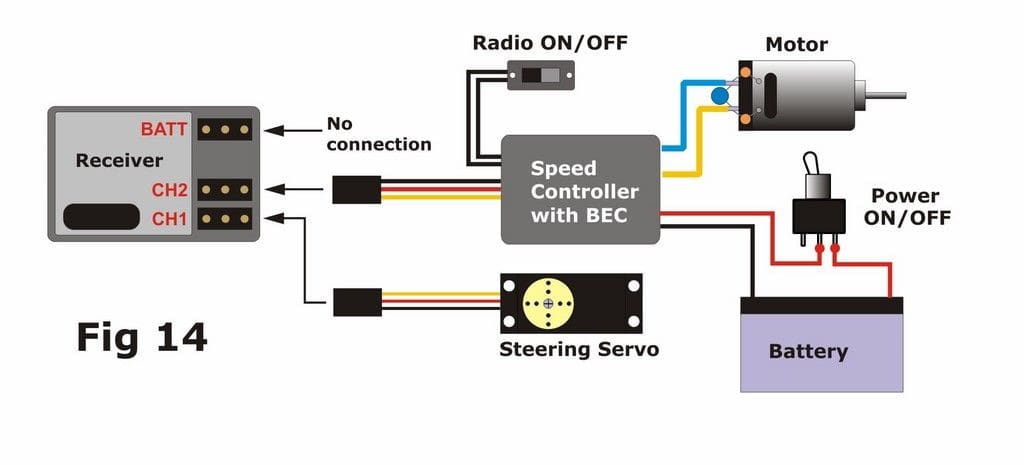
Once you know the voltages and currents you can go ahead and plan the installation. For a simple single-motor model with just a speed controller and a steering servo that’s an easy task, especially if your speed controller has BEC (Battery Elimination Circuit). This is a little circuit built into the speed controller which reduces the voltage from the main motor battery and passes it down the 3-wire connection from the speed controller to supply power to the receiver, Figure 14. When a speed controller doesn’t have a BEC then you can either fit a remote one or power the receiver from a separate 4-cell NiMH pack.
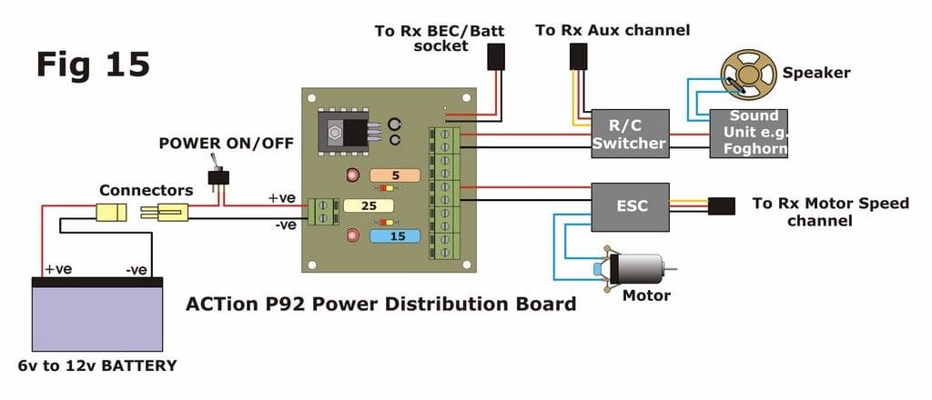
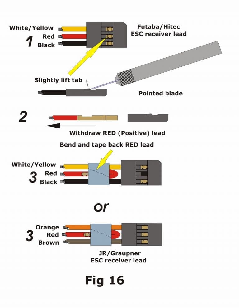
For more complicated installations you might well consider using a power distribution board such as the ACTion P92, Photo 15. This takes the power from the main battery and directs it through fuses to five pairs of terminals, all at the same voltage as the supply battery. It also has a reduced-voltage fly-lead with a plug to power the receiver i.e. the BEC device is fitted onto the power board and not inside the speed controller, Figure 15. A similar fused power board, albeit with switches and without the BEC output, is available from Hunter Systems while there is a very sophisticated version from Harbor Models of San Diego which includes voltage reduction for the outputs as well. With this you can use just one 12v battery to power two 12v circuits, two 6v circuits, two 3v circuits and the 4.8v receiver! It does however come with a hefty price tag and because of its size is really not suitable for small models. Note that where you have fitted a BEC speed controller you must NOT also use a separate power supply to the receiver such as a battery pack or the flylead on the ACTion P92. Further, if your model has two or more BEC-equipped speed controllers then you must disable the positive wire to the receiver on all but one of them, Figure 16.

Where multiple voltages are required, a little bit of planning can often resolve the matter down to using one battery. For example, if your main power supply is 12 volts but you want to run a 6v lighting circuit from it as well, then simply have two 6v bulbs in series as one circuit (total supply voltage = 12v). You could incorporate a resistor instead of one of the bulbs, but it will usually need to be of a very low resistance and high power capacity in order to ‘absorb’ the unwanted power. It will, of course, also get pretty hot in operation. In such circumstances it’s easiest to hide the second bulb internally if you can’t make use of it elsewhere on the model. If you do find yourself needing a different voltage for just one circuit then it’s often the best advice to use a separate battery to supply that circuit rather than mess around with resistors etc.
If you really do have problems with planning circuits then you could take a look at the ACTion website, which includes over 170 full-colour wiring diagrams for all sorts of model boats from simple launches to multiple screw warships. See www.action-electronics.co.uk. It is naturally biased towards ACTion’s own products. but the principles of installation apply equally to most electronic gizmos.
Fuses
My friend and mentor, the late Craig Talbot, wouldn’t hear of fitting fuses into a model boat as: ‘They don’t prevent anything from being destroyed by a determined idiot’! I admit that I followed this until I witnessed a fire in a model which could so easily have been prevented had a fuse been fitted.
The purpose of a fuse is primarily safety. A fuse probably won’t stop a stalled motor from blowing the output FET’s in a speed controller, but it will blow fast enough to stop cables and contacts from overheating and catching fire. Choose a value which is just a little above that at which you get nuisance blowing of the fuse, e.g. try a 5A fuse in circuit with a 10A ESC (electronic speed controller) and if it continually blows when the motor is at full load, replace it with a 7.5A one or even higher rating if required, but don’t exceed the maximum rating of the ESC with the fuse value. For those who want to know whether to fit a fuse between the battery and ESC or between the ESC and the motor, there’s no harm in doing both, but you must ALWAYS fit one in the positive line between the battery and the ESC somewhere. This is also the place for the main On/Off power switch.
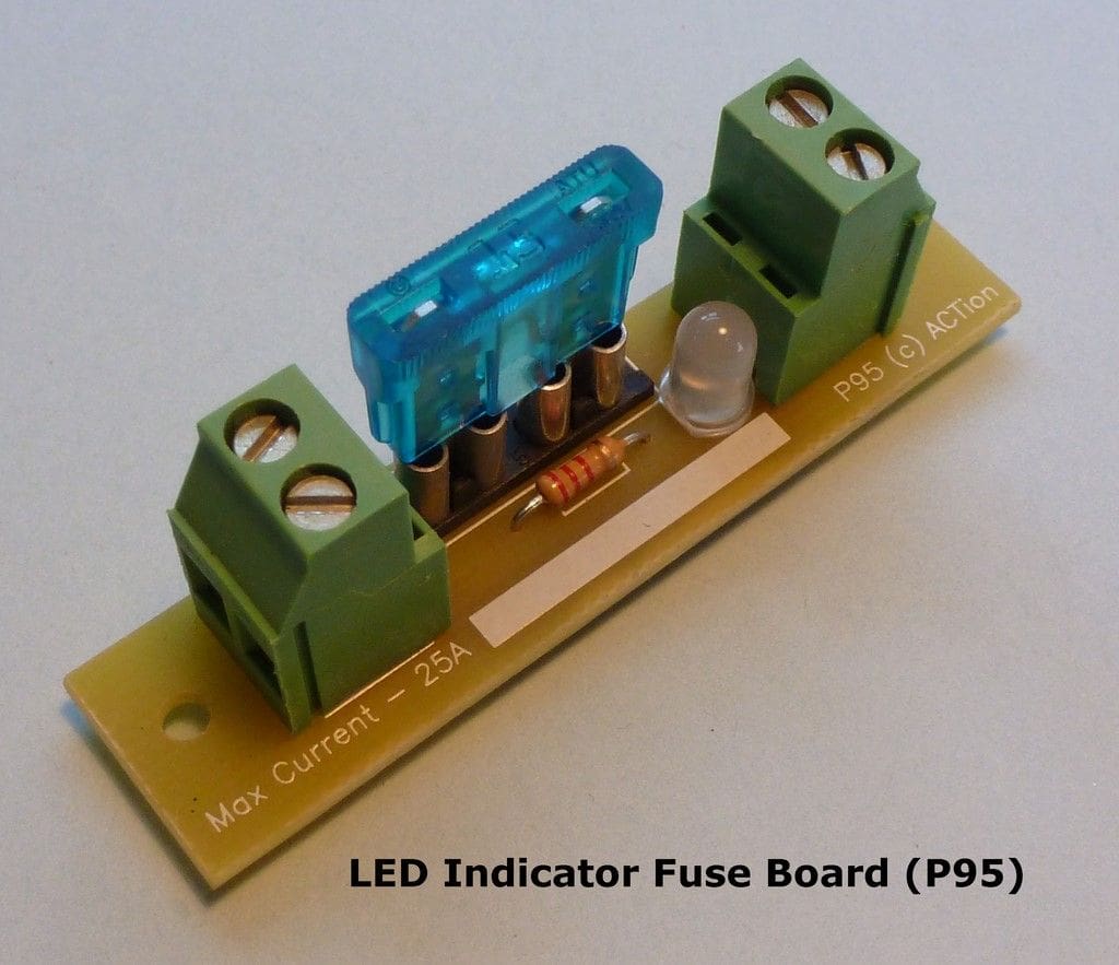
For fuse values of less than about 2A you can use those clear glass cartridge fuses fitted to an in-line, spring–loaded holder. These aren’t very useful for higher currents, as the contact area at each end of the fuse is very small which can produce excess heat and melt the holder. I favour the automotive ‘blade fuses’ which go up to 30A, are widely obtainable, and are not expensive. You can even buy a fuse holder for these with an indicator diode which glows either red or green depending on which way the current is flowing, which is very useful for setting motors up, Photo 16. Finally, don’t fit fuses or fused boards inside a box or have them way down deep in the hull as you’ll need to be able to get to them easily for checking and replacing them.
Motors
Electrically-powered model boats exclusively use Direct Current (DC) motors, although there are thousands of different types and sizes. Essentially they all involve using the power supply to energise a coil or coils of wire inside the motor. These coils form the armature of the motor. The electrical energy creates a magnetic field in the coils which in turn rotates the armature inside the motor. The armature shaft extends beyond the end bearings in the motor case and the propeller shaft is connected to it via a coupling. There are very many websites which show their construction and operation, with both coloured diagrams and animated graphics.
Brushed motors
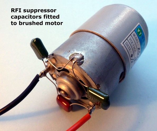
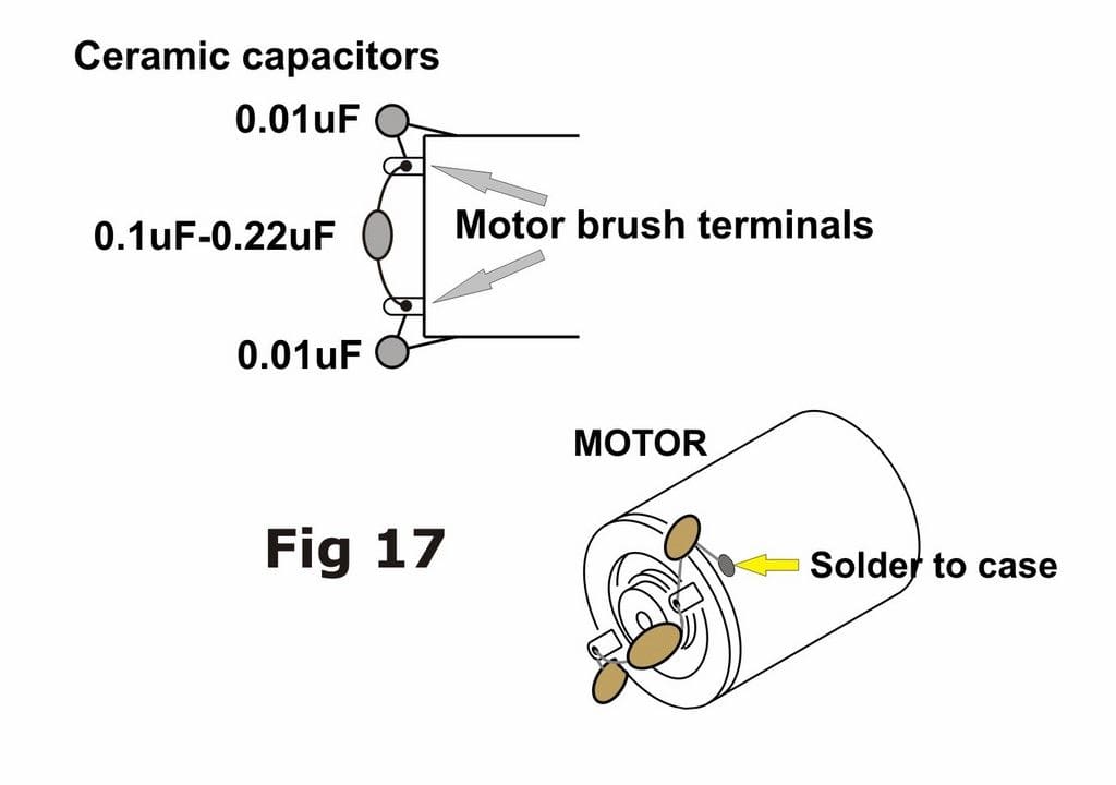
In what we call a ‘brushed’ motor, the coils of wire are wound around the poles of the armature which is caused to rotate inside a permanent magnet or magnets. These magnets are fixed around the inside of the motor case. The almost-universal way of conducting the electrical current to the coils of wire around the armature is via fixed carbon ‘brushes’, which rub tightly against brass contacts on the armature as it spins around. These contacts form what is called the commutator of the motor. The rubbing action creates quite a lot of friction and heat; it can also create electrical sparks which in turn put out a very messy radio signal. This unwanted radio frequency (called RF) can interfere with the signals received by the radio in your model and cause servos to twitch uncontrollably. This effect is known as Radio Frequency Interference or RFI for short. You can, and should, fit small suppressor components called capacitors to the motor as shown in the diagram, Figure 17, to eliminate the effects of RFI, Photo 17.

Motor suppression is not as necessary if you are using a microwave-frequency radio (2.4GHz), but if you are sailing with others who aren’t, then the RFI created by your motor might just be ‘loud’ enough to interfere with their radios. Further measures may be needed if the RF still causes twitching servos in your model. These can include earthing the case of the motor(s) to the propeller tube; twisting the two wires from the speed controller to the motor together and/or passing these wires through and around ferrite rings. A full treatise on suppressing motors can be found on the Internet at:
http://www.modelsoundsinc.com/articles/DavidsOriginalArticles/RFIArticleMarch2006.pdf
Brushless motors
Over recent years there has been a major revolution in model motor technology with the advent of brushless motors. As the name suggests, these don’t rely on fixed brushes to transmit the power to the central armature. Rather they are made ‘inside out’ with the wire coils fixed around the inside of the motor casing and a permanent magnet rotating the shaft inside them. The power to energise the coils is transmitted by some very clever, fast-switching electronics outside the motor case. Because there are no brushes, these motors are much more efficient than their brushed cousins, so a small and light brushless motor will do the same job as a bigger, heavier brushed one. There are no brushes to replace and so the motors are virtually maintenance-free. They are, however, very hungry for power and so heavy-duty cable and batteries which can supply high currents are required (usually NiMH or LiPo types). They also have a couple of other limitations in that low-speed control is not yet as good as with the brushed types and there are only a few speed controllers available which will allow remote selection of forward and reverse. Because they have no commutator to create RF interference, brushless motors don’t require suppressor capacitors, which should please the ‘solder-phobes’!
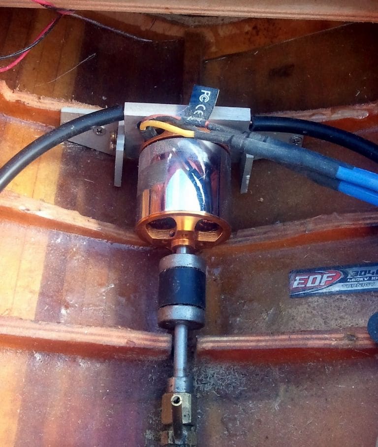
Just to muddy the waters a little further, there are two types of brushless motor. Those where the outer casing of the motor is fixed to the mount and the shaft rotates within the casing are called ‘Inrunners’, while those which have a shaft fixed to the rotating outer case are ‘Outrunners’. The latter type is more useful for model boats as they generally have higher torque and lower RPM than the former. In model boats the water-cooling of brushless motors is sometimes necessary; more frequently with the higher-revving Inrunners but occasionally where the load on an outrunner is relatively high. This is achieved by using the propeller to force cold water from the pond through a scoop just behind the propeller blades into a flexible tube. The water passes through this tube into a specially-made motor mount and conducts the excess heat away through a small exit outlet in the side of the hull. In many cases this cooling water also needs to pass through the speed controller, which will have tubes already fitted for the purpose, Photos 18 and 19.

At the moment the general practice seems to be to use brushless motors where speed is the main criteria for performance, with brushed motors still being by far the most popular for model workboats, warships and submarines, but like the man says, you pay your money and you take your choice! Just remember that you cannot run a brushless motor using a brushed-motor speed controller and vice versa.
Speed controllers
If you want to know how an electronic speed controller works then I’d refer you to the article on the ACTion website as it’s far too long to reproduce here. Please see: http://www.action-electronics.co.uk/pdfs/ESCs.pdf
In the bad old days we used to use mechanical variable-resistance speed controllers, operated by a standard servo, which controlled the speed of the motor by ‘bleeding off’ unwanted power. A contact on the end of a wiper arm moved across a coil of resistive wire like a rheostat, or a miniature electric fire. This was very wasteful in terms of battery power and the advent of the Electronic Speed Controller (ESC) has made these almost extinct. Okay, users of ‘Bob’s Boards’ will object to that statement, but matching the correct resistive board to the motor was always critical to operating the things and few users seemed to manage to do that successfully. The contacts also could work loose in operation, would only handle relatively small currents, and required regular maintenance.
The modern electronic speed controller comes in two distinct types, depending upon the motor, that’s brushless and brushed. We’ll concentrate on the latter here, as most of what applies to brushed types also applies to brushless.
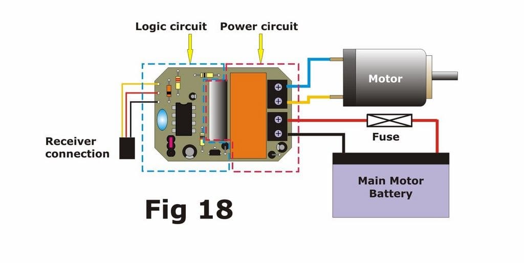
There are two distinct parts to the inside of an ESC; the logic circuitry and the power circuitry, Figure 18. The logic components are the ones which are connected to the receiver via the 3-wire lead with a plug on the end. Its operating voltage is dictated by the receiver and is generally of the order of 4.8v, but you don’t need to make a conscious decision about that as the receiver will take care of it. The purpose of the logic circuitry is to detect and decode the signal coming from the receiver and to switch the high-speed, high-current semiconductors in the power circuit which control the speed and direction of the motor. The ESC manufacturer will state in the technical information the range of main motor battery voltages with which the ESC will cope, along with what should be a value for the maximum motor current (in Amps) which the ESC will handle under continuous operation. You should be guided by those two values when choosing your ESC, after first ascertaining the working voltage of the motor and its current consumption under load as described earlier.
I’ve emphasised the words ‘under continuous operation’, because the current rating often causes confusion and I suspect, involves a little skullduggery on the part of some sellers. When you switch on an ESC and bang open the throttle there will be a sudden inrush of current from the battery to the motor to get it spinning. This will always be a larger value than that consumed when the motor is running at full speed, i.e. continuously. Modern switching semiconductors therefore have two current rating values; one for continuous and one for ‘inrush’ or pulsed currents. The value we should be concerned with is the continuous current rating. Because it is a much more impressive figure, I have long suspected that certain oriental ESCs are rated with their inrush current instead. Indeed, we have handled supposedly 50A ESC’s from such sources which failed consistently at 15A. So, the moral is clear; buy a known unit from a reliable source with a good reputation and a clearly stated service/warranty policy. Popular UK-manufactured ESC’s are by ACTion, Electronize and Mtroniks, while other popular and reliable imports carry the Graupner or Robbe labels. Make sure also that the ESC has both forward and reverse if you are fitting out a workboat like a tug. Many of the cheaper ones are forward-only or have limited reversing capability. Incidentally it’s quite okay to run a low-current motor on an ESC which has a much higher rating, but not the other way around.
The power circuit connections of an ESC will always comprise a pair of thick battery cables. These are usually made in red and black, for positive and negative connections respectively. There will also be a pair of cables to connect with the motor terminals, often in blue and yellow, but be careful and check your instruction leaflet first. Brushless motor ESC’s have three motor wires. It doesn’t matter which way round you connect the motor wires to the motor, BUT the battery connections should NEVER be reversed. If you wish to reverse the direction in which the motor is rotating then just swap over the two wires from the ESC to the motor. For brushless motors swap over any two of the three motor wires.
Setting up the ESC to operate from the radio can either be a real pain or none at all, depending on the type chosen. Some require you to move the transmitter stick to its neutral and extreme positions while you push a small button on the ESC in response to flashing coloured LED’s. Others have rotary trimmers and slide switches which can adjust the working frequency and the neutral and peak motor speeds. Others, you just switch on, and they ‘Autoset’ themselves! Brushless ESC’s are a law unto themselves and frequently require a separate programming card.
The only other variable is whether or not the ESC contains a battery eliminator circuit (BEC – see earlier). If it does, then you must NOT connect an additional power supply to the receiver. Some BEC-equipped ESC’s have a small slide-switch on a pair of thin wire leads. This usually controls the onward power from the internal BEC voltage regulator to the rest of the radio system and therefore serves as a radio ON/OFF switch. It does not control the power supply from the battery to the ESC, so I would recommend also fitting an addition high-current switch in the positive lead from the main battery to the ESC unless you are in the habit of disconnecting the battery physically each time you remove the model from the water. If you do disable the BEC for any reason, then leave the little switch in its ON position or you may find that the ESC doesn’t work; again, this should be covered in the ESC Instructions.
Modellers have complained about the high-pitched whine that some speed controllers appear to emit at low motor speeds. In fact it’s the motor which is making the noise and it’s caused by the very high frequency at which the motor is switched on and off. This is usually only audible at very low speeds. If it annoys you, then the only solution is to change to a speed controller which operates at a lower frequency, whereupon that whine becomes a low-frequency buzz. Some ESC’s are switchable between high and low frequency, but that is more because high frequency ESC’s are more effective at low speed control.
Whichever type of ESC you buy, read the instruction manual before you do anything with it. Of those units which were returned to us ‘for repair’, at least 50% had nothing wrong with them; it was usually a case of the user thinking he knew more about how the ESC should work than the guy who wrote the instructions. If ever you hear an electronics engineer muttering about ‘Hardware-User Interface Conflict’ then you’ll now know exactly what it means!
Motor Mixers
Twin electric motors can be operated by various means. You can run two motors in parallel from one ESC or you can operate two separate ESC’s from one receiver channel. In both of these cases the motors will run at the same speed and in the same direction together. If you wish to do what the full-size boats do however, you can split the two motors between two separate channels and use a transmitter stick to control each one independently. This is called ‘tank steering’ as it’s the way a tank driver controls his vehicle. It allows much better low-speed control for manoeuvring into a dock, and it can also greatly improve the turning ability of a model. However you’ll have spotted that it required two channels for the throttles and it’s also quite a complicated skill to learn.
You can alternatively fit an on-board device called a motor mixer, which is coupled to the throttle and steering outputs of the receiver and automatically slows down or reverses the inner motor in a turn as you apply a steering command. There are several different types on the market (e.g. Mtroniks, ACTion, Hunter) and also a combined twin speed controller and mixer, the ACTion P94. I’d suggest you have a look at the article: http://www.action-electronics.co.uk/pdfs/Twins%20Ver2.pdf, which explains and illustrates further how these units work.
Radio Control Switches
You can’t just connect a load like a bulb to the output pins of a receiver and expect it to operate when you move the transmitter stick, because the receiver is not itself a switch. It puts out a signal voltage pulse through one wire of each channel’s connectors. The length of these pulses is varied by movement of the stick or switch on the transmitter and ranges typically between 1 and 2 thousandths of a second (1-2mS) as you move the stick. The other two wires of the channel’s output are at 0v and +5v all of the time. In order to make sense of this variable signal pulse, the device which is plugged into the receiver needs a circuit to detect it, decode it and change it to drive an output which can be used by the load. In a servo this output drives the servo motor. In a radio-controlled switch it operates either an electromechanical relay or a semiconductor, which in turn, switches an external circuit, e.g. lights, winch motor, sound unit.
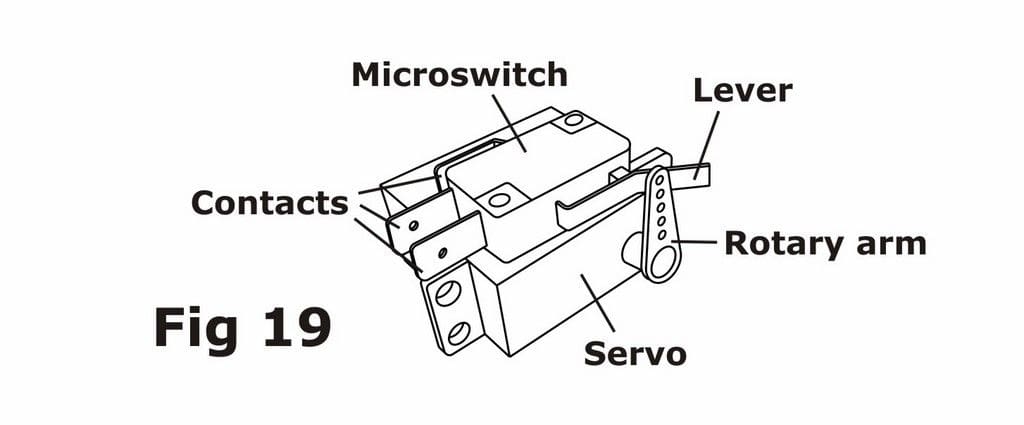
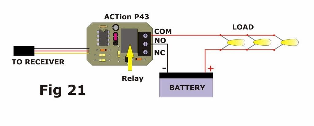
The original remote switch for model boats was a sensitive mechanical type called a microswitch, mounted on top of a standard servo. The button of the microswitch, or a lever connected to it, was depressed by the rotating arm or disc of the servo, so making the electrical circuit connected to the switch. Figure 19. The contacts are the same as a conventional single-pole changeover switch, Figure 20. Some modellers still cling to this method, largely I think because they don’t understand the workings of a servo-less switch. A simple single-relay switch has exactly the same contacts as a microswitch and is physically much smaller than the servo + switch assembly. It plugs into the receiver exactly as a servo does, and requires no further setting up such as bending levers or repositioning the servo arm to make/break contact at the appropriate point, Figure 21.

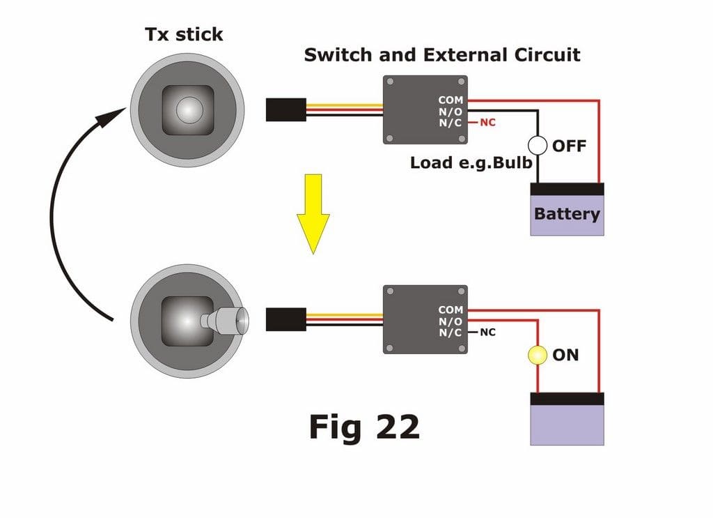
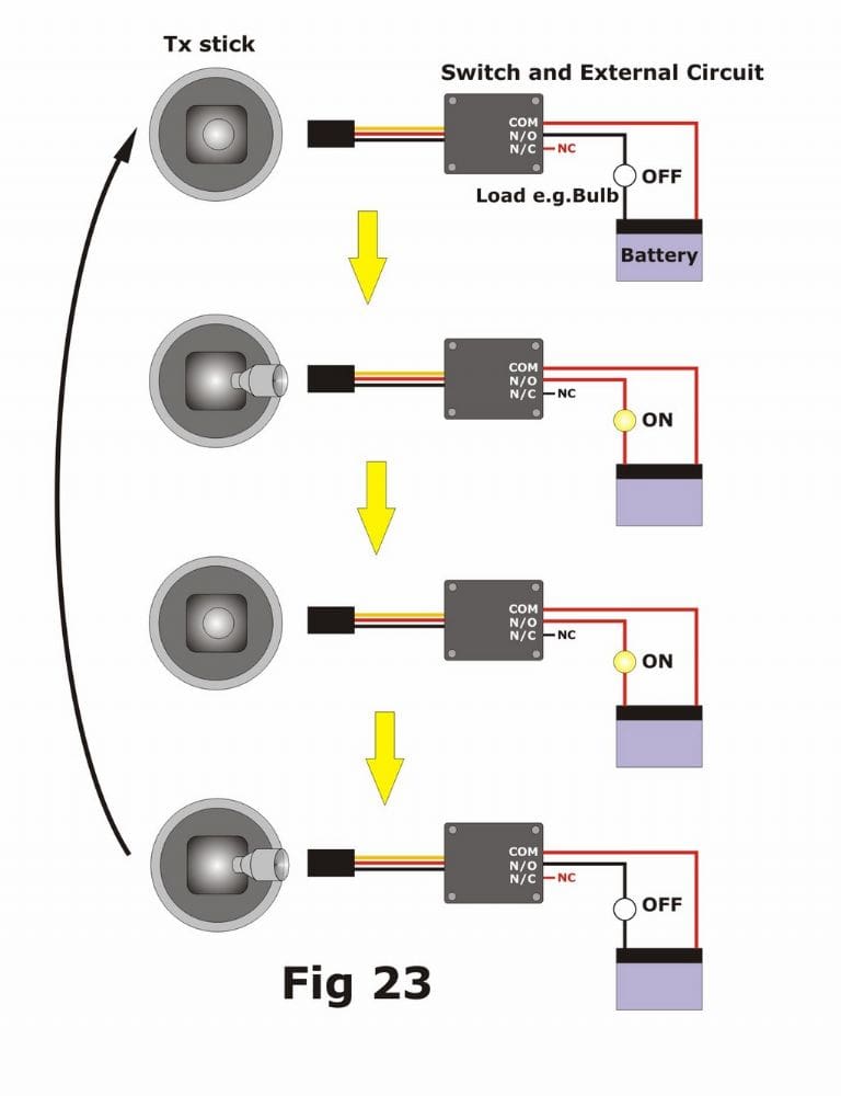
Radio control switches can behave like a bell-push, where the circuit is live only for as long as you hold the transmitter stick or switch in the ON position, Figure 22. The alternative is that they operate like an Anglepoise lamp switch, where you have to push and let go of the switch to turn it on, and then repeat that action to turn it off, Figure 23. The latter is called a latching switch while the former is, unsurprisingly, a non-latching switch. Each has its place within a model; for example you would use a latching switch for any load which you want to keep on for a while, such as lights, whilst a non-latching switch would be more suitable for a horn or whistle.
Some r/c switches can operate up to eight separate circuits from just one channel but beware! Those simple 2-way switched channels on multi-channel radios which are often marked with legends like ‘Retracts’ or ‘Flap’ are capable only of operating a single function switch (i.e. On or Off). Practically this limits them to one lighting circuit, a single sound card or a continually-rotating motor like a radar sweep arm. For two or more circuits per channel, then you need a spare radio channel which is operated either by a stick, a rotary knob or a 3-way switch (Centre = Off).
The main selection criteria for a switch is the current which the load to be switched will draw. Typically one Grain of Wheat bulb will draw 60 to 80mA; an LED will draw 20mA; a 12v smoke unit will draw 1 to 2A and a geared 12v winch motor between 1A and 5A depending on the motor size. Calculate the total current for each circuit and then buy the appropriate switch. With relay switches, the voltage doesn’t seem to matter as long as it doesn’t exceed about 30v whereas switches without relays can be limited to well below that value. Again, do some research before you decide. Popular makes of r/c switches include Electronize, Hunter Systems, Technobots, ACTion and Robbe-Futaba.
Engine sound units
If you wish to add realism to your model, then pretty much the obvious choice would be an engine sound, ideally one which increases in pitch as you open the throttle. Take care that this is a realistic choice however as I doubt very much if you would have heard the engines of HMS Hood or the Titanic unless you pressed your ear to the hull and the very popular KD Perkasa was powered by three gas turbine engines, not petrol or diesel!
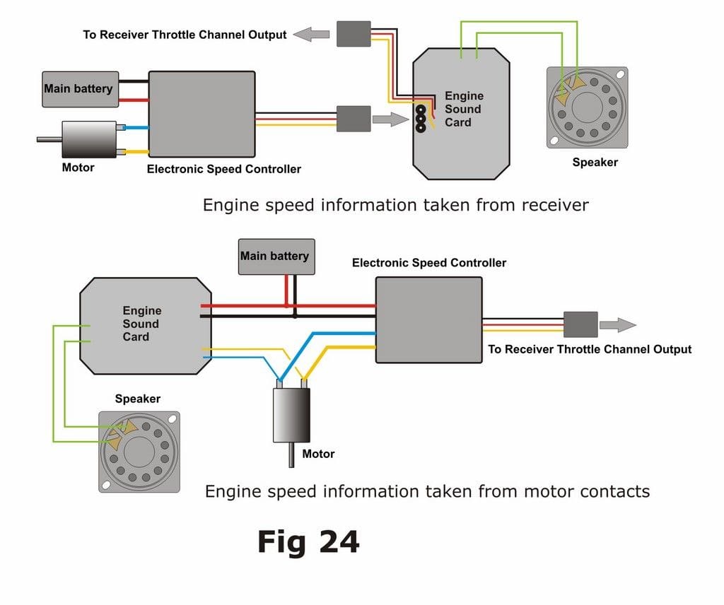
Such sound units are available in two basic types; those which simply simulate the sound of an engine by generating and modifying electronic noises, and those which replay digital samples of real engine recordings. In order for the pitch to be varied there is a connection either to the brushes of the motor itself or to the receiver throttle channel output, Figure 24. In the former case it’s important to know the voltage of the main battery, because the sound card runs directly from it. In the latter case the sound card takes its signal and power from the receiver so the main motor battery voltage isn’t relevant. Sound simulators are generally adjustable for volume, pitch, idle and top speed and some sort of character or tone, e.g. number of cylinders in a diesel engine, while the digital replay types are usually only adjustable for volume.
In nearly all cases, engine sound cards will have an amplifier chip built into their circuitry, so the only other item to fit will be a suitable speaker. Make sure you use the correct impedance, which is usually 4Ω or 8Ω, but check the instructions. The exception is the ACTion P100 Noisy Thing, which requires an external amplifier to work. Most sound cards will benefit from the addition of an external amplifier to increase their volume, as few seem to be suitable for all but fairly small lakes. Model Sound Inc’s Shockwave digital system has a very powerful on-board Class-D amplifier which makes it suitable for large model aircraft and helicopters, but a high supply voltage and large speakers are required to obtain the optimum performance from this unit.
Note that a straightforward engine sound card doesn’t require a separate radio channel to operate, as it simply uses the throttle channel to vary its pitch. Some units, however, may require a second channel e.g. the Mtroniks unit needs one to start up the engine sound while the P100 carries up to eight other sound effects (horns, bells etc.) which can be activated by a second channel and selector switch.
Engine sound simulators are made by Technobots, ACTion, Harbor Models, Robbe, and JoTiKa while the more expensive digital types are from Mtroniks, Benedini, ACTion, Model Sounds Inc. (Canada) and Graupner. Model Sounds Ltd (UK) make a fixed-pitch sound unit called Master Blaster which is switched on manually and allowed to run for the whole sailing session. This is useful for a heavy marine-diesel sound, which varies very little with throttle anyway and other types are available. Note that the digital types can all be programmed with different engine sounds, some by the user and others at the time of purchase. Once again, check out the manufacturer’s website for all the details.
Other sounds and speakers
Most of the manufacturers just mentioned, also supply sound units for other ship’s noises, e.g. fog horns, air horns, bells, whistles, telegraph, sirens, destroyer ‘whoops’ etc. These tend to be the synthesised kind that is adjustable by the user as required. Some will be supplied with their own speaker and perhaps a microswitch so that they can be activated by a servo; others will need a separate speaker and some sort of r/c switch to operate them. You will need a spare radio channel for these sounds. You can operate more than one sound unit at a time, but if you are using just one speaker then you must fit a separate audio amplifier/mixer (e.g. ACTion P97 or P101), or fit a separate speaker for each unit. Two sound cards wired directly to the same speaker is almost the quickest way to a blown unit that I can think of and nearly as quick as connecting the power supply the wrong way around!
The question of speakers arises. The sound quality from a paper cone is without doubt better than any other type, BUT don’t forget you are only going to hear the sound from quite a distance, so real hi-fi quality would be wasted. Mylar or polypropylene cones are better for model boats because they are waterproof (or rather, splash-proof), in that they probably wouldn’t survive being submerged while turned on. Speakers do have polarised connections, i.e. there is a +ve and a –ve marked on the solder terminals. If your sound unit or amplifier is also marked with the polarity of the speaker outputs then do connect them up, like for like. However, it isn’t vital that they should be connected like that; you won’t damage anything if they aren’t.
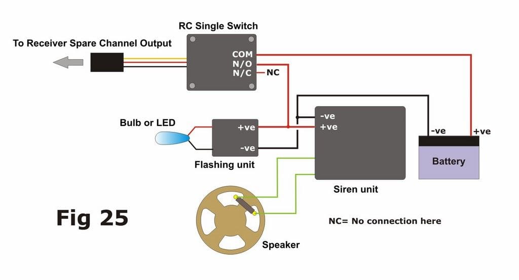
Figure 25 shows a siren unit connected to an r/c switch with a flashing light unit wired in parallel. This is popular for fire and rescue models and shows how several of the different items in this article can be operated together. In this case the siren will sound and the light will flash when the switch is operated.
Lights
Fitting working lights to a model boat is often not the easiest of tasks. Many are placed in awkward positions, e.g. at the top of a tall thin mast. This will require good planning and thin cable, and if lights are going to be inaccessible after fitting then you are best advised to include them in a parallel circuit. That way if one does fail then the others will continue to work. One common way of reducing the number of wires needed in a mast installation is to make the mast of brass tube and use it as a common negative connection for every light. That way you need only a separate positive wire for each bulb or LED.
You need to plan how many separate circuits you want, because you will need a separate switch for each one. For example, you might want the navigation lights and mast lights on one circuit, while the bridge and interior lighting is on another. This is where twin or multiple switches (e.g. ACTion P44 or P62) are handy, in as much as you can operate two or more circuits from one channel.
The question then arises whether to use LED’s or conventional bulbs. LED’s have the advantage of a much longer operating life and lower current consumption (about a third of that needed for a Grain of Wheat bulb), but they usually require a series resistor to make them compatible with the supply voltage and they are only bright when viewed from quite a narrow angle, like in a spotlight. Component Shop’s catalogue has a very informative article on using LED’s as well as a calculator for working out the value of series resistors. Internet tools are also available e.g.: http://www.muzique.com/schem/led.htm Another option, especially for very small lights, would be to fit a powerful bulb or LED inside the model and run optical fibres from it to the sites of the lighting points.
Smoke
For some modellers there is no option but to have a funnel belching smoke as the model steams away from the side of the lake. If you are considering fitting such an effect then make sure, as with an engine sound, that this is appropriate for the type of model, e.g. modern large diesels will give a cloud of dirty smoke on start-up, but then run without any visible exhaust, while other vessels have exhausts situated below the waterline.
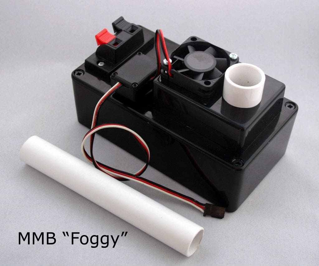
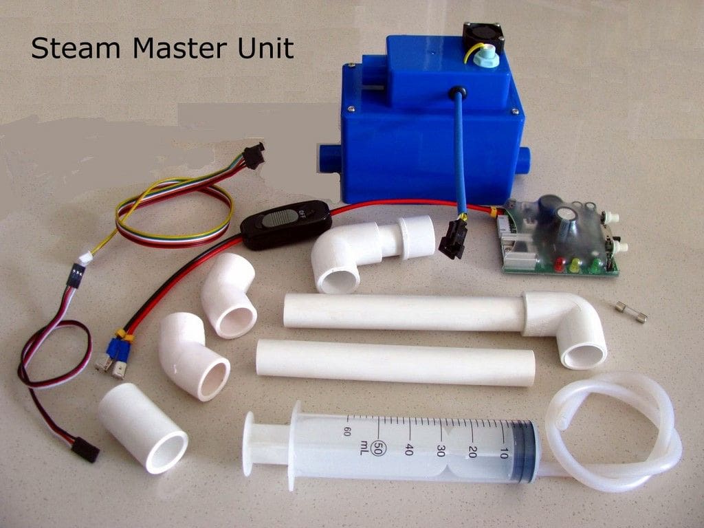
Smoke or steam simulators work on two different principles. The first type e.g. Marks Model Bits’ ‘Foggy’ has an internal nebuliser and runs on water. The nebuliser creates a mist of water vapour which is then forced up a short plastic funnel by a small computer fan. This is quite a bulky unit and requires a 24v power supply to run (or a 12v/24v voltage converter). A more sophisticated version is available which has a small speed controller to increase the speed of the fan and thus the volume of smoke as the throttle is increased. The newer Steam Master unit does essentially the same thing, but works on any supply from 6v to 20v. It’s also smaller, but produces greater volumes of steam; has four different, programmable smoke outputs and is nearly twice as expensive.
The other type of smoke unit actually does produce real smoke, usually from a commercially-available hydrocarbon-based distillate. This oil is retained in a metal reservoir which also has a wick inside it. This soaks up oil and is ignited by a heating element to produce the smoke. This exits the funnel, either with or without help from a fan, as per the Foggy system. Hunter Systems’ unit works on 12v, but has no fan assist, while the daddy of them all has to be the Harbor Models unit. This 12v ‘squirrel cage’ blower-assisted unit is expensive, but mightily impressive and there is a video on their website.
The other pros and cons I have heard, are that the water-based units are ineffective in hot or humid countries, while the oil burners can leave a sooty residue all over the model. Oh, and you won’t get black smoke from either type, at least not safely, Photos 20 & 21!
Other functions
The variety of working functions which can be incorporated in a model boat is largely down to the imagination and ingenuity of the builder and the budget available. There are no fixed rules about how these things can be operated, but here are a few suggestions:
Bow thrusters: Often incorporated in models of workboats such as tugs and ferries, these are small electric brushed motors fitted inside a tube which runs from side to side at the bow of the model, below waterline level. Water is drawn into one side and expelled from the other, applying a turning force to the bow (or stern) of the model. Typically the motor will run from 7.2v and needs a speed controller which will give equal power in both directions. Connect it to the channel which is operated by a sideways-movement of the transmitter stick and this is usually the opposite stick to the main steering one.
Working winches: These use a geared motor run either by a speed controller or a 2-way relay-based switch, with or without limit microswitches to prevent over-running. MFA/Como Drills have a very large range of geared motors and also a selection of plastic gears, chains, racks, pinions etc. to make up a drive train.
Doors, ramps, deck lifts, retractable antenna: Either use a geared motor as above, or a suitable servo. ACTion’s P96 ServoMorph is a handy device which can vary the total amount, direction and speed of rotation of a standard servo. Model aircraft retracting-undercarriage servos will turn slowly, have high torque output and will rotate 180 degrees with a normal transmitter signal. Sail winch servos will rotate several times from one extreme of signal to the other. Both types can be adapted for these sorts of function.
Gun turrets: Again, use either a geared motor and 2-way switch or a servo. Technobots have a dedicated Servo Position Controller which can be made to move a servo and stop the rotation at any point by returning the stick to centre without the servo following it. This clever little unit can also increase the degree of rotation as well as adjust its speed. It is only available as a kit to build on stripboard, however. Multiple turret servos can be made to rotate together by interconnecting them using Y-leads. Servo rotation can be reversed by either a controller such as the P96 ServoMorph or a simple and cheap reversing lead (available from Component Shop and others).
Fire monitors, bilge pumps: Use a geared water-pump suitable for the voltage available (Robbe and Graupner market several) and switched by a high-current r/c switch, e.g. ACTion P91. Note that the motors in these pumps are not often rated for running continuously for more than about 30 seconds at a time. Ignore such warnings at your peril!
And finally: Which channel is which?
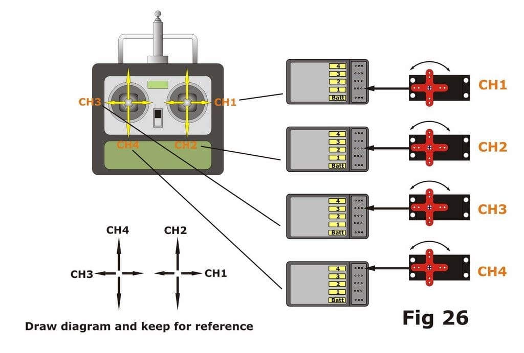
All multi-channel receivers have labels to inform you which numbered channel you are connecting your device into, but very few have the corresponding labels on the transmitter sticks. I am frequently asked: ‘How do I know which set of pins to use’? The answer is to experiment, or try it and see. Plug a servo into Channel 1 of the receiver, switch on the transmitter and receiver and wiggle the sticks until you find which movement of which stick moves the servo. Now draw a diagram of the transmitter in the notes section of the radio’s manual and label it. Switch off the Rx, move the servo connection on to Channel 2 and repeat. Do this for every channel and you’ll end up with an accurate picture of your Tx showing the correct stick/switch for each Rx output. Simple, innit – please see Figure 26!
Suppliers’ website details:
www.action-electronics.co.uk Speed controllers, RC switches, power distribution board, fuse boards, motor mixers, sound units, ServoMorph, Wiring Diagrams*
www.benedini.de Engine sound systems
www.component-shop.co.uk Batteries, connectors, leads, cable, chargers, LEDs, ACTion R/C Electronics units*
www.electronize.co.uk Speed controllers, RC switches, motors
www.engel-modellbau.eu Magnetic switches
www.graupner.de/en Speed controllers, sound units, pumps
www.harbormodels.com Smoke unit, sound units, power distribution board
http://shop.huntersystems.co.uk Smoke unit, power distribution board
www.jotika-ltd.com Sound modules
www.marksmodelbits.com Foggy smoke/steam generator*
www.mfacomodrills.com Motors, gearboxes, gears, chain, sprockets, pinions, pulleys etc.
www.mtroniks.net Speed controllers, mixers, motors
www.modelsolutions.ca Engine sound systems
www.modelsounds.co.uk Sound modules
www.jperkinsdistribution.co.uk Power analyser*
www.rapidonline.com Test equipment*
www.robbe.de Speed controllers, sound units, RC switchers, pumps
www.steammasterunit.co.uk Steam/smoke generator*
www.technobotsonline.com Servo Position Controller, engine sound simulators
www.4-max.co.uk PP-Budget Wattmeter
*The author wishes to acknowledge these suppliers for the use of their photographic images included in this article. Other photographs by the author, Paul Freshney, Nick Keur and Tim Fawcett.
Please also note that all ACTion R/C Electronics products are now only retailed by Component Shop
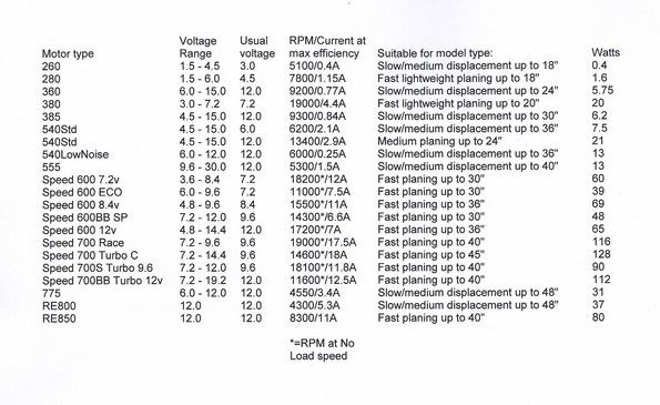
Electric Motor Nomenclature
When looking for suitable motive power for their model boats, many people are confused by the descriptions of electric motors by manufacturers and suppliers and it is indeed something of a minefield for the less experienced modeller. The table below is intended to give some rough guidance in respect of characteristics and applications for the more commonly listed motors.
Note that it takes no account of different prop types/sizes, weight of model etc, and the performance figures are from manufacturers or suppliers published data (and not independently verified). That said, it’s a reasonable place to start from!
(Click on smaller image underneath for a larger version)