RON REES and another ‘Messing about with boats’ article
 article.jpg)
It’s that sort of ‘twilight’ time again. The trees are turning amber and red and you need to rake the leaves off the grass yet again. I had already chosen my winter project and this was the very nice looking Halvorsen 38ft Seaplane Tender featured in the 2012 MB Winter Special Edition. I was assembling the bits and pieces that I would need for it, but I was not quite in the mood to start the project just yet.
I needed something to do, but knew not what. It was while I was chatting to fellow modellers at the International Model Boat Show at Leamington Spa, that we got on to the subject of ‘The Brushless Question’! There were a few of us looking at the models of the Vintage Model Boat Company and the owner showed us how he had powered some of his models with this new technology. Some confusion seems to reign over the use of these motors and I was surprised at the misconceptions that were coming out. I’ll look at this later on and maybe write a simple article about the subject in the future, but in the meantime, I bought one of the motors, a neat little 2810 1100kv outrunner, that is to say it is 28mm diameter with a 10mm long case and 1100 times a 7.2 volts battery equals a running speed of approx. 8000 rpm. This motor was only £10 and I now started thinking about a suitable project for it.
Enjoy more Model Boats Magazine reading.
Click here to subscribe & save.
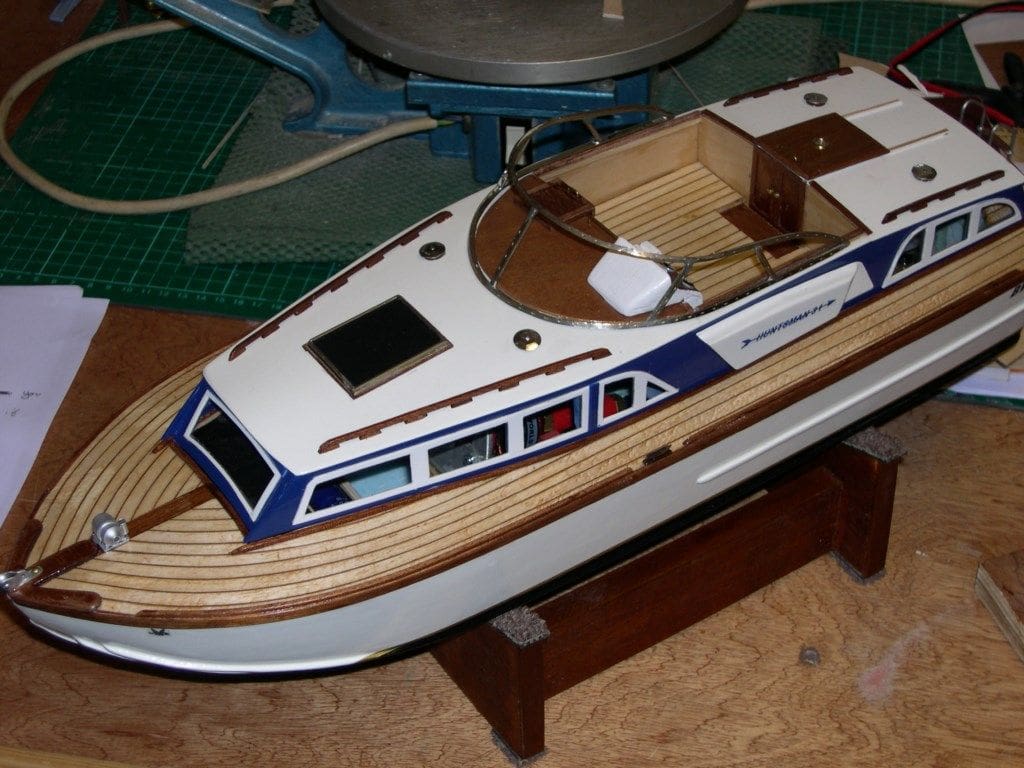
A suitable model?
Back home and quite a few pounds lighter (and I don’t mean losing fat!), with a cup of tea in hand, I began thumbing through my pile of model magazines and came up with the Model Boats August 2007 edition with guess what? My favourite type of model, another Fairey motor launch. This time it was an 18 inch long Huntsman 31 by Richard Webb with a great article and a free plan. I have Richard’s book ‘Making Model Boats with Styrene’ and he knew what he was talking about, so I was sure it would be a good model and the only reason I had not already built it was that it was totally made out of styrene, so now I had an idea of what I wanted to do. (Richard Webb sadly passed away just a few years’ ago – Editor)
Dave Brumstead came up with some 1mm styrene sheets for me, so I settled down to making card patterns. Now I will admit that despite years of building models, I have never really ‘got into’ this material in a big way, apart from using it to make small items such as ammo’ lockers, deck furniture and so on. I am a wood and metal man at heart, but I thought I would give it a go just the same.
Getting started
Following Richard Webb’s instructions to the letter, I cut out all the hull and deck parts, which took about an hour. I then spent about three hours cutting all the off-cuts of styrene into 6mm squares with scissors to make a thick gap filling glue paste. I remember looking longingly at my wife’s very expensive cross cut paper shredder and thinking, ‘I wonder if’? Anyway I resisted and just put sticking plasters on my, by now, blistered thumb and fingers instead!
The next part of putting the hull and deck together was very tricky. Maybe because I am not very confident using this stuff on large areas, but more probably because I am cack-handed with hands like bunches of bananas. Anyway, the tape kept coming undone, the sides wouldn’t stay in line, it all came apart when I put the transom in and the deck with its pronounced camber, just went any way it liked. It wasn’t the model, it was me! The full story I won’t recount, as the language is not acceptable in polite society or in a quality magazine.
If only there had been some bulkheads or formers it may have been easier, I am sure that there must have been a way to calculate the sizes of these, but without a hull to measure, my brain gave up and I put the hull parts to one side and turned to my ‘bodging’ skills once again.
How to make a hull with no formers
When starting to build a model boat, there is no doubt that the largest investment of time, effort and materials go into the making of a good hull. After that, all the rest is just good fun, fiddling with all the little bits and pieces. Because of this fact, most kit manufacturers invest a great deal in the manufacture of a hull for their customers because people don’t want the trouble of going to all that effort. Any means of making this stage quicker and easier must be a good thing and I have had loads of fun finding out how modern materials can be experimented with to this end, hence my idea here of carving out a chunk of foam, not as a pattern but as an integral part of the model and also to see how easy it would be to make a hull like this and how well it would work.
I thought I would make use of the card templates taken off the plan and found a rather sorry and dirty looking piece of blue closed cell polystyrene foam originally from an industrial refrigerator in a builder’s skip. An idea was gradually growing in my head as I looked at the foam block. I had used this stuff for product prototyping in the past and had taught industrial model making to the kids at school for their exam courses, using it because of its ease of working, finishing and stability. This block was one of a family of foams which include Polystyrene (Styrofoam) Board, Polyurethane Foam (sometimes made by mixing two brown chemicals together and also available in a spray cans for building use) and Polyethylene Foam (often used as packaging of high cost fragile items like TV’s etc.). They all come in blue as well as other colours and are a world away from the white polystyrene used for moulded packaging which is hard to sand as it breaks up into little balls and is also very fragile.
Polystyrene (Styrofoam) Board is available from art and craft shops, or Hobby’s Catalogue, and can also be found online for building work. It has a fine grain, closed cell structure that is very stable and quite strong. It is easy to cut and saw for which a serrated bread knife is a useful tool. You can test to see if it is styrene by putting a drop of Acetone, Plastic Weld or plastic glue on it. It will then melt quickly leaving a sticky hole, but it is also 100% waterproof.
Another way of getting a block of suitable foam is to use a spray can of Polyurethane (brown) Foam and empty it into a cardboard box or plastic bag. It expands and sticks to everything, but once hard can be trimmed with a breadknife into a useable block.
Polyethylene Foam is only good as crash padding as it can be cut easily, but not sanded, so is not suitable for what we want in this instance.
While trying to find a good supplier of Blue Styrofoam for this article, I remembered a superb company that supplies Design Technology Departments in schools. I gave them a ring and they confirmed that they would supply a catalogue and materials to non-education customers. They do a host of amazing stuff of interest to model boaters, are extremely helpful and are well worth looking up. Contact details are Technology Supplies Ltd., website: www.technologysupplies.co.uk tel: 08455 670000.
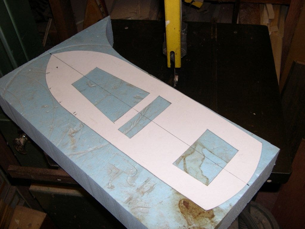
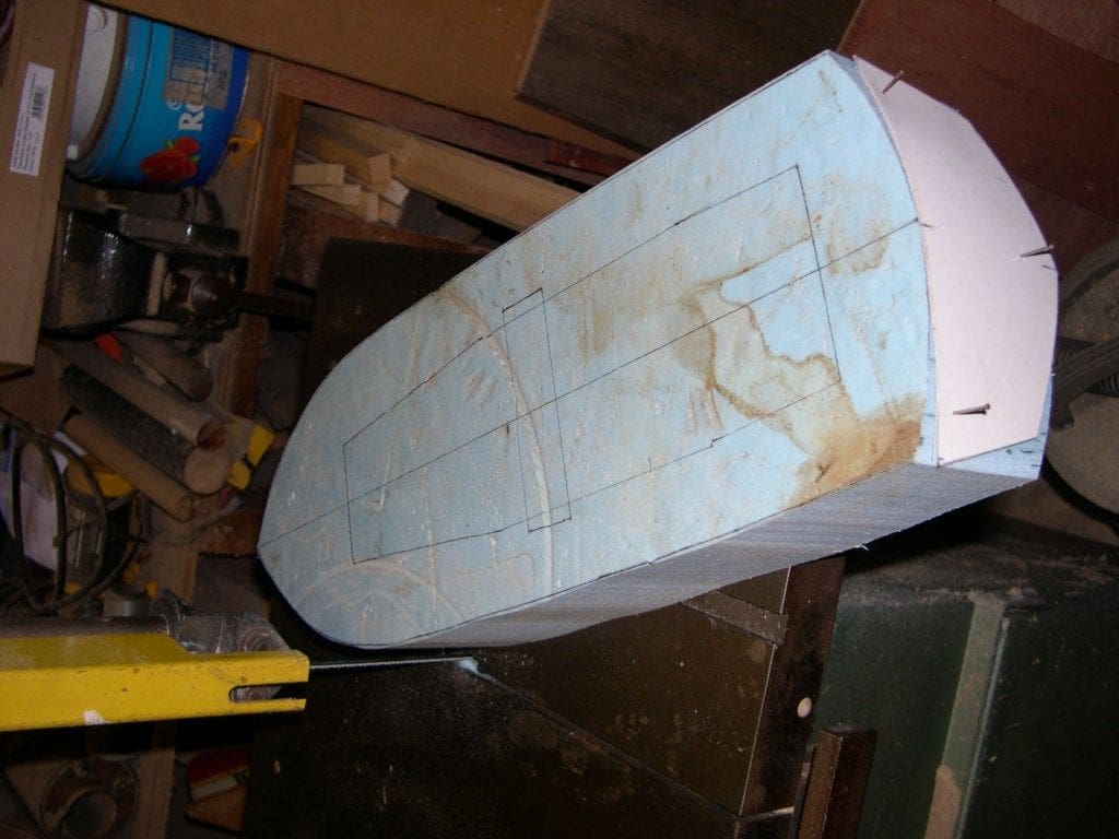
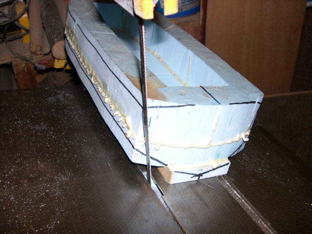
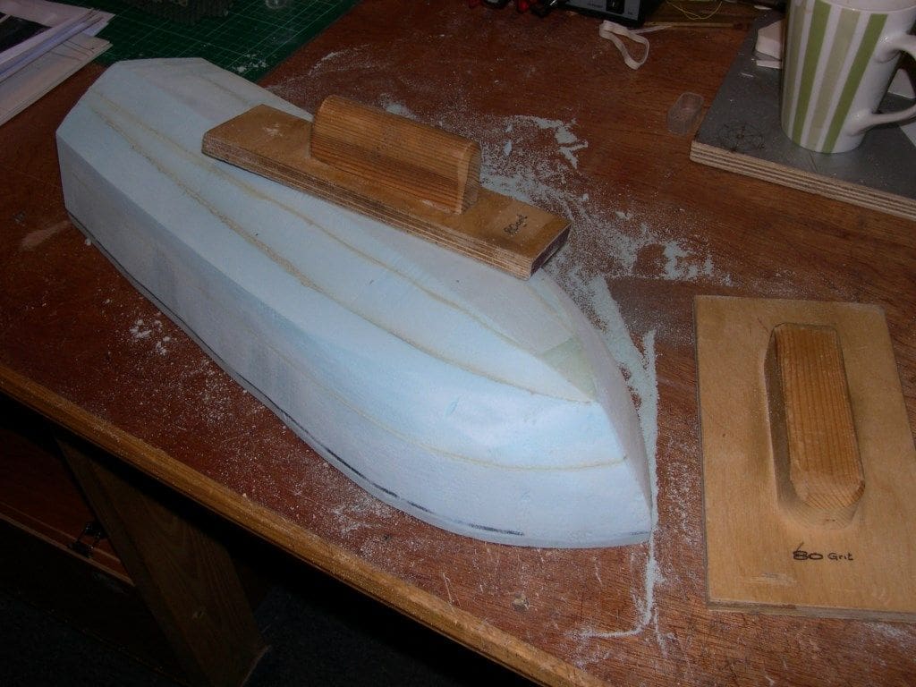
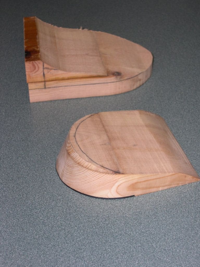
Cutting out the blank for the hull
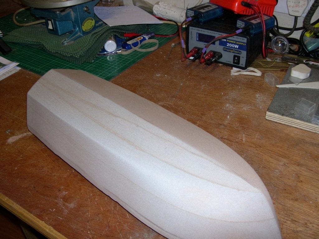
As can be seen from the pictures, after marking out from the original templates, I cut the block into the rough shape for the hull using a bandsaw, allowing 3 to 5mm for sanding and fettling to shape. The problem comes when we need to hollow the block out so we can install all the hardware and this is where ‘cracking an egg to make an omelette’ comes in. I have in the past made a simple Hot Wire tool to do this which was just bent stiff wire glued to a piece of dowel, heated up with a blow torch and applied to the foam, but unfortunately it always moves any way it likes and melts more away than you want.
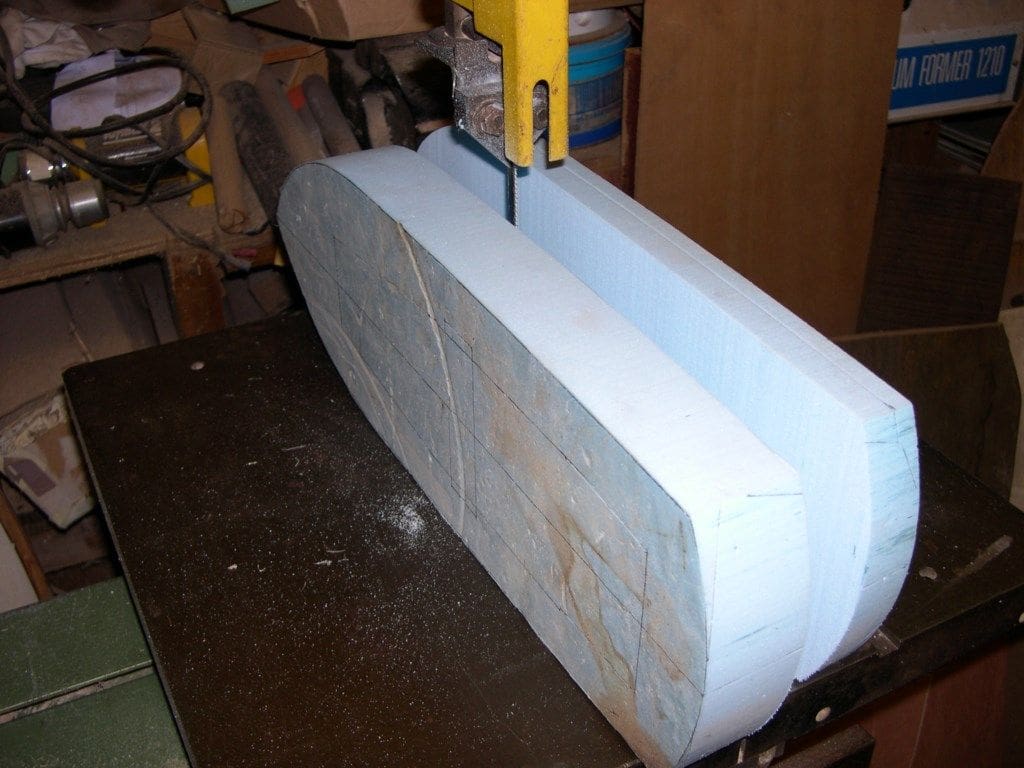
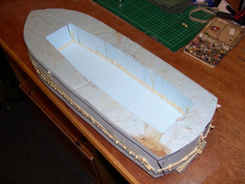
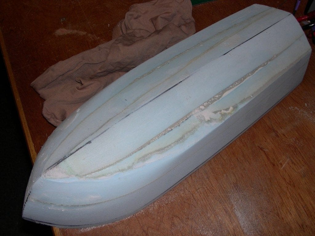
I decided this time to mark out the space needed for the inside, cut the whole bottom of the block off, cut out the inside and then glue the bottom back on again before carving the whole thing to shape. You could alternatively always laminate pieces of foam together in a ‘bread and butter’ fashion as it depends on the thickness of foam that you find to use.
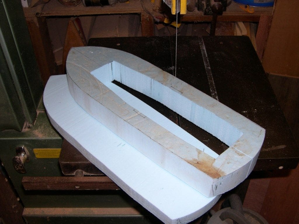
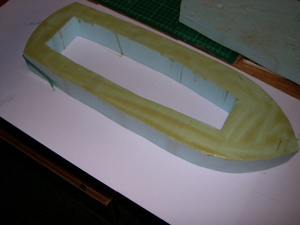
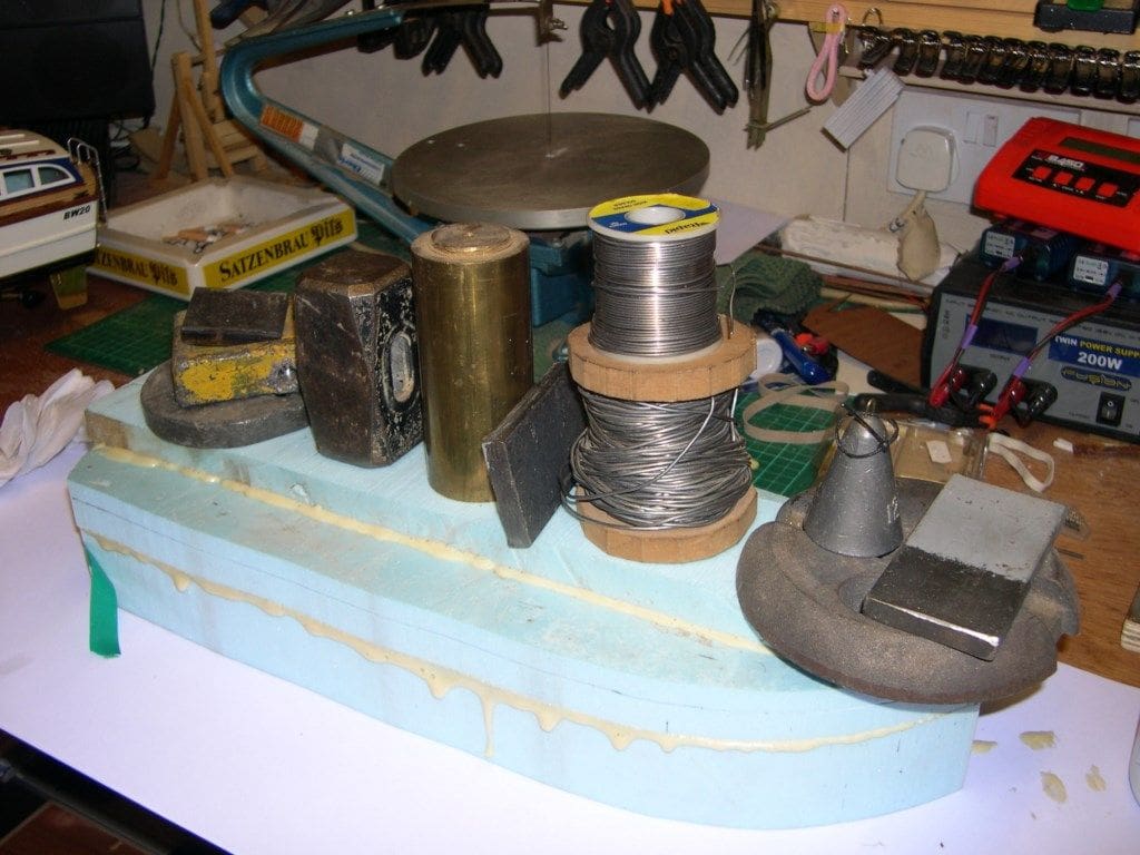
After sawing off the bottom of my three inch (75mm) thick block, I cut out the insides, sawing right through the centre at the transom to get to it. Once hollow, the transom and the bottom were stuck back together (held in place using tape and/or weights) with Polyurethane Wood glue or Gorilla Polyurethane glue, which foams and sticks this stuff ‘like you know what to a blanket! However, once dry, it sands just like the main block of foam.
With the card patterns to help and further carving to shape with the bandsaw, bread knife and 60 grit sandpaper stuck to pieces of plywood, I ended up with a fairly accurate foam hull. I finished off with an all-over rub down with 80 grit sandpaper making sure to keep the corners sharp. A quick hoover up of all the blue dust and scrap bits and it was ready for covering.
At this point I think it is important to warn budding foam modellers of the ‘elf and safety’ aspect of all this. Do not be tempted to hold the hull against a powered disc sander, except for very light trimming. It appears to be so easy to do, but this foam melts at those sanding speeds and will grab the disc in an instant, throwing the hull across the workshop and usually smashing it. That is apart from the distinct risk of you then sticking your knuckles into the revolving disc when the hull is wrenched out of your hands and I wonder who has done just that……….
Skinning the foam hull
The carving of the hull shape is so easy, and all the foregoing actually took an hour to do, which is a bit of a joke when compared to framing and sheeting a hull of this type and size in the traditional way. Another aspect of this type of construction is that you can easily produce a hull given those overlaid half drawings of a hull shapes at different points along the length, a type of plan favoured by Jim Pottinger and others. You need only cut a set of stiff card outside templates and using a centre line and markings down the length, sand down to where the templates fit snugly. The whole strength of the model relies on the skinning stage and you would be amazed at what a tough and unsinkable hull this method produces.
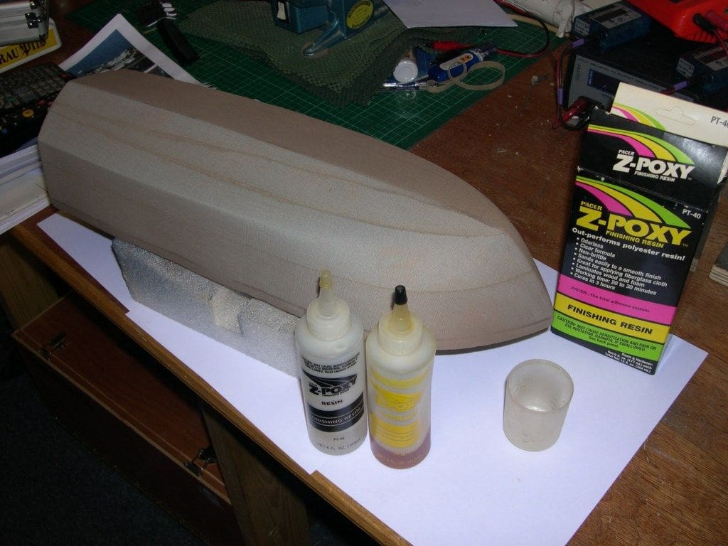
It is important now to remember that Polyester resin, as in glassfibre work, will melt the hull in seconds and the described method used MUST be done with two part epoxy resin, available in most model shops and I used Pacer Z-Poxy Finishing Resin from Al’s Hobbies.
This may seem an odd way of making a load bearing structure, but it is now at the heart of all home built full size lightweight aircraft construction. In fact you have to do test lay-ups of foam, resin and cloth which are checked by a CAA inspector before you can begin your full-size build to prove you can do it properly.
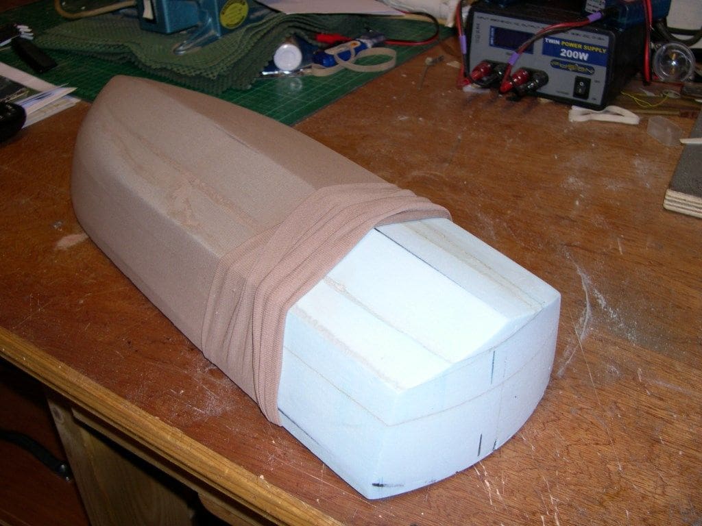
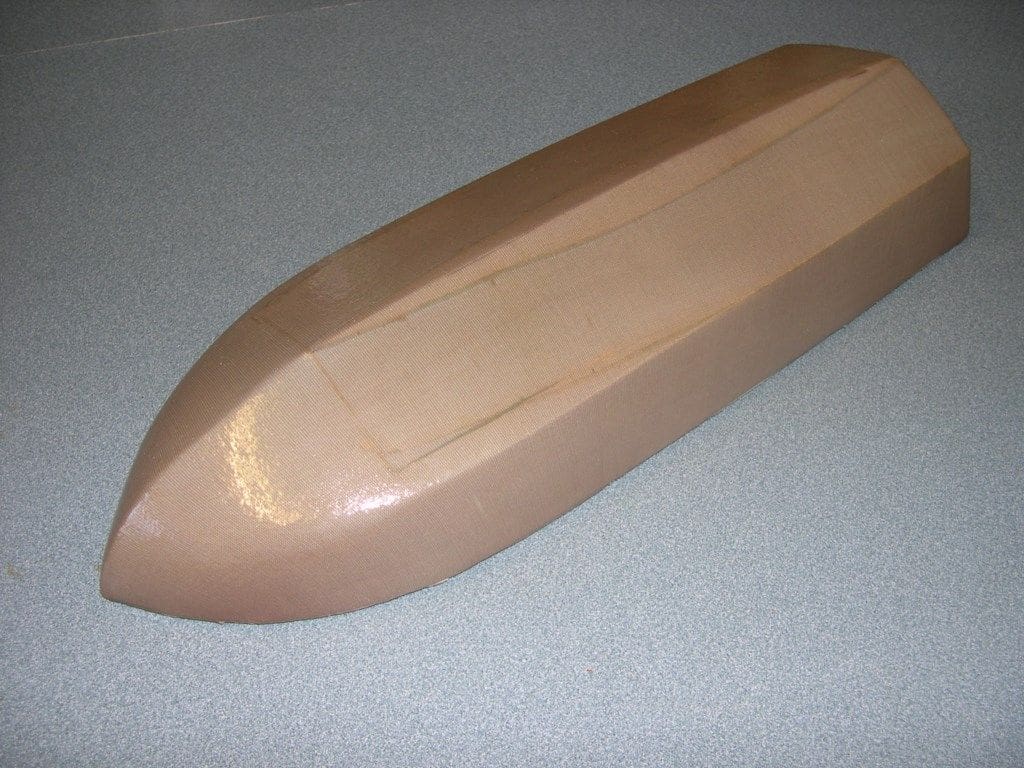
If the model was bigger I would, of course use woven glass cloth, but this model’s barely 20 inch length suited my ‘nylon stocking’ method really well, with no joins or difficult corners to worry about.
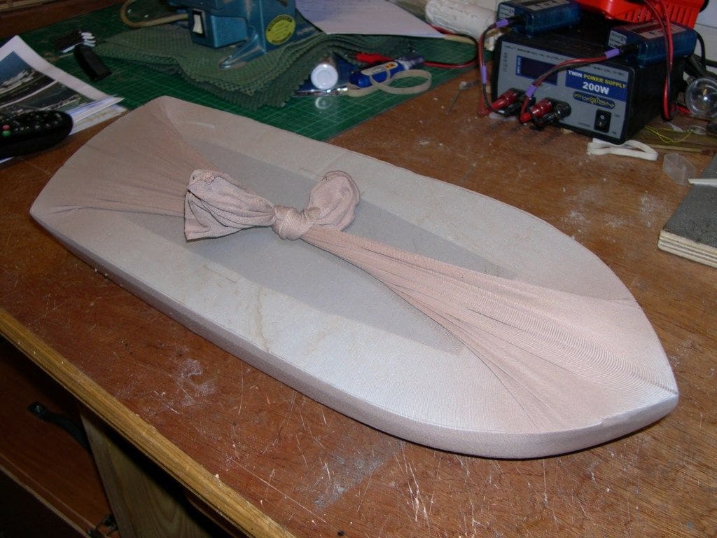
Unless the foam hull, which is a bit fragile at the moment, is very huge, elbowing it into one leg of a pair of nylon tights is easy and once it is enclosed very little squeezing pressure is exerted on the foam. As opposed to weight per square metre of glass cloth, we are into the realms of nylon stocking measurements here. The lower the ‘Denier’, the finer the fibre. For example, 15 Denier would be regarded as pretty fine and you would need at least two layers on a hull like this. I was lucky, as the ‘missus’ was throwing out a pair of support tights, as she called them. Anyway, they were 30 Denier and quite thick, so only one layer was needed. Try not to use the bit where the toes go and twist and pull it to ensure that any ‘ladders’ (technical jargon!) are over the deck area where they can be cut off later.
Keep it clear of the workbench by lifting it up on to a block and cover the bench with a bit of newspaper to soak up any drips. Brushes can be cleaned with cellulose thinners or acetone so keep the workshop door open till the air has cleared. After a couple of coats and a couple of hours, but leaving overnight is best, rub down with 180 to 200 wet and dry sandpaper used wet with a drop of washing up liquid in it. Wash off with clean warm water to leave a slightly matt finish all over and allow to dry properly, but NOT on the radiator!
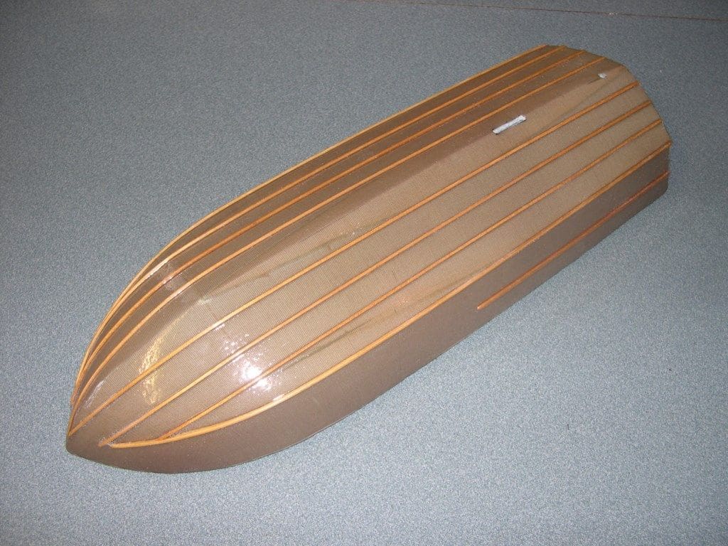
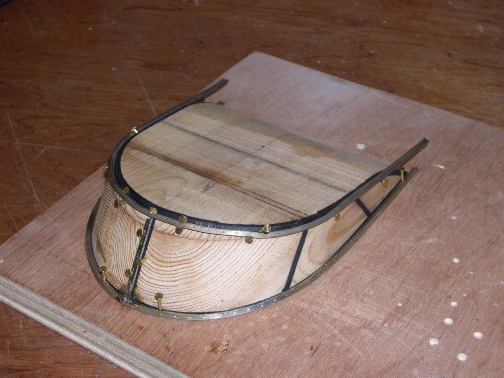
Fitting the hull strips
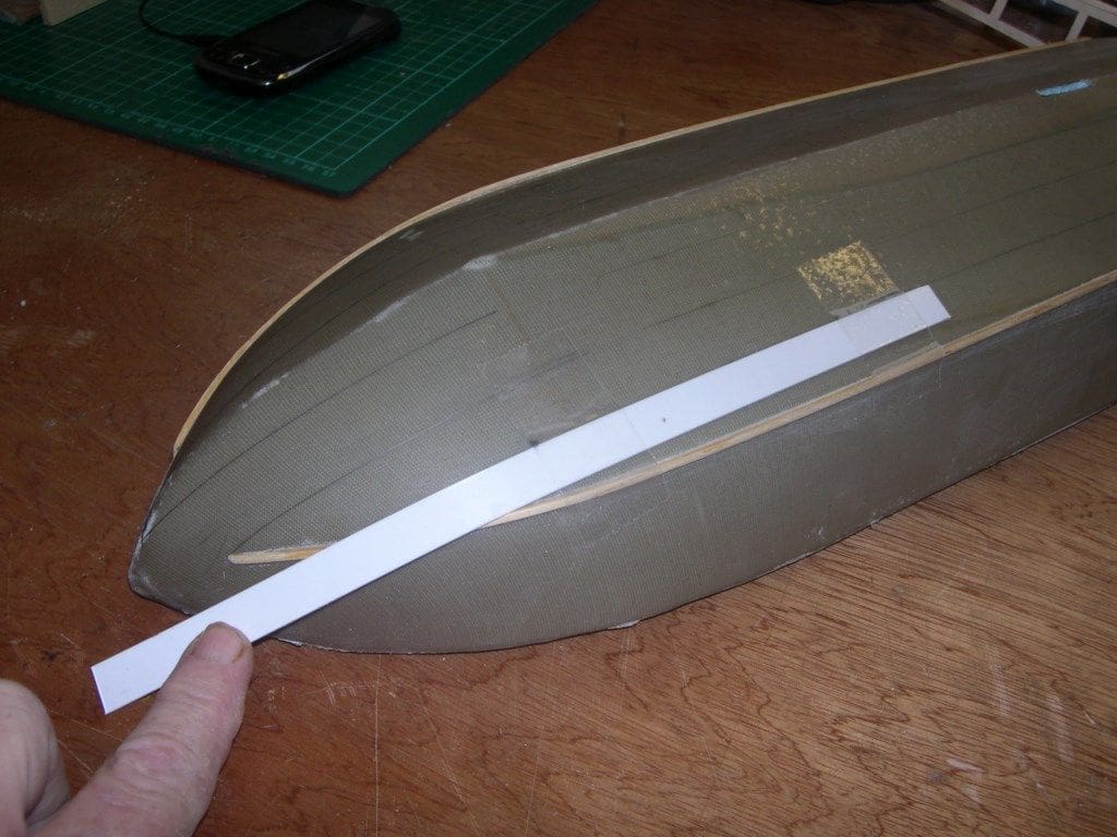
Fairey Marine boats in their Huntsman series have chine edge strips and hull bottom strakes fitted and they really work well on the model, so shouldn’t be omitted. These strips further reinforce the hull and allow it to turn and track in a straight line like it’s on rails. It is amazing how such simple things can positively affect the way a model behaves.
Take the time to mark out exactly where they are to go, I used a strip of 1mm styrene as a bendable straight edge to follow the curves. Then strips of 1.5mm square hardwood positioned at the bow with a drop of medium superglue, held in place with the tip of a scalpel blade or similar until dried. The strip is then slowly lowered on to the hull and a little drop of superglue used at intervals to hold it in place along its length. Once fully in position. tilt the hull on end and run a bead of thin superglue down its length. Do it right the first time and they will not come off. Chamfer the ends and then give them all a light rub down for which foam sanding blocks will round the edges just a trifle and leave a nice finish. The whole hull will be given one more final coat of resin later, once the mahogany deck edge strip is fitted, but that has to wait until after the hardware installation and deck planking is completed
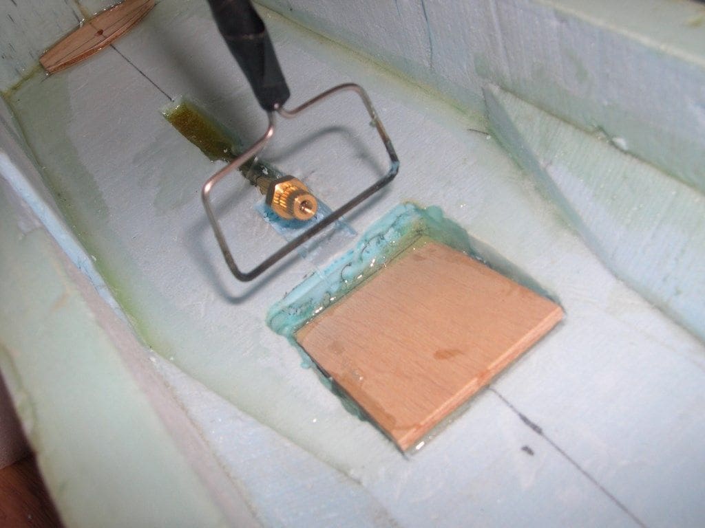
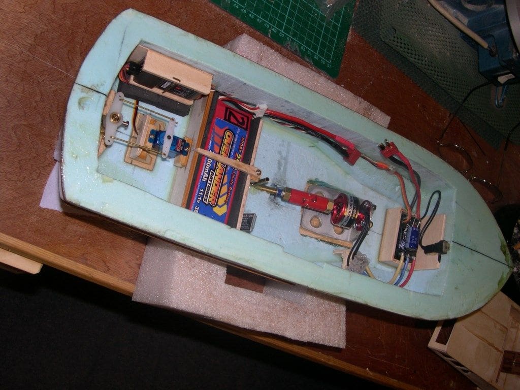
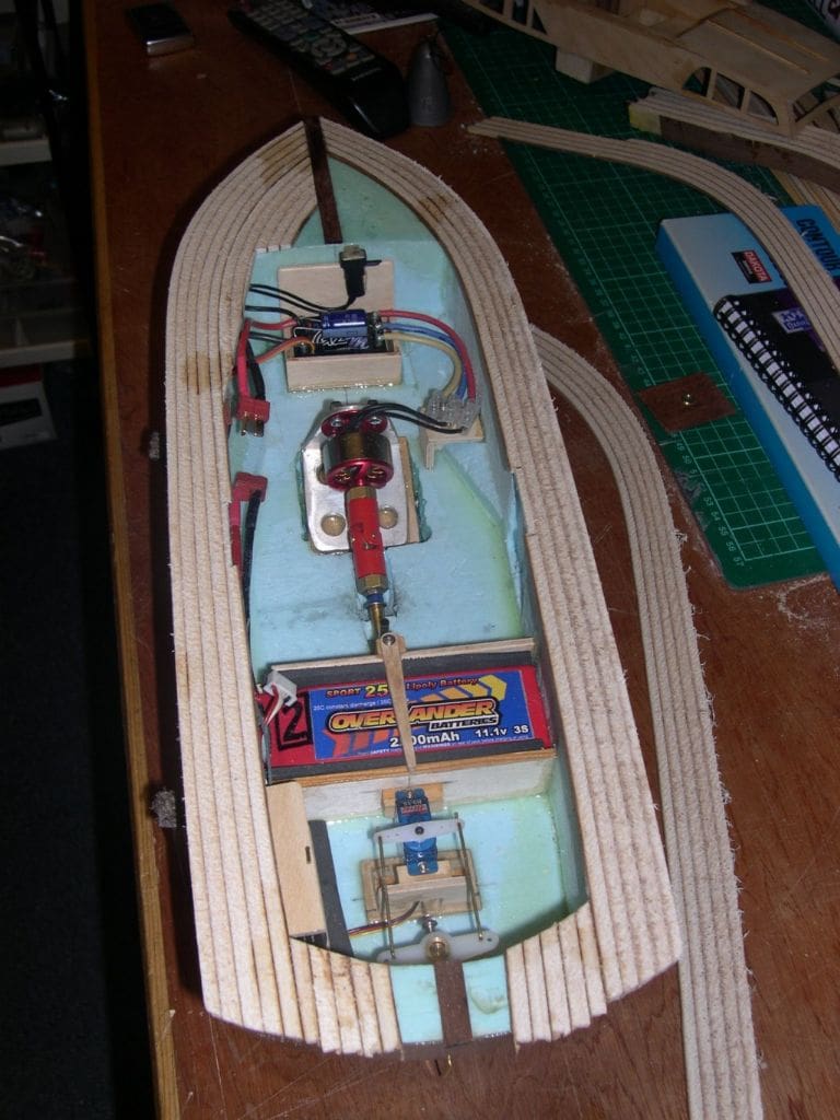
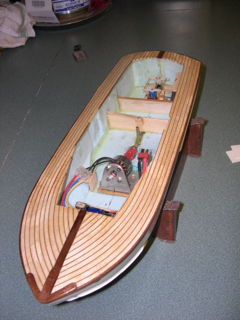
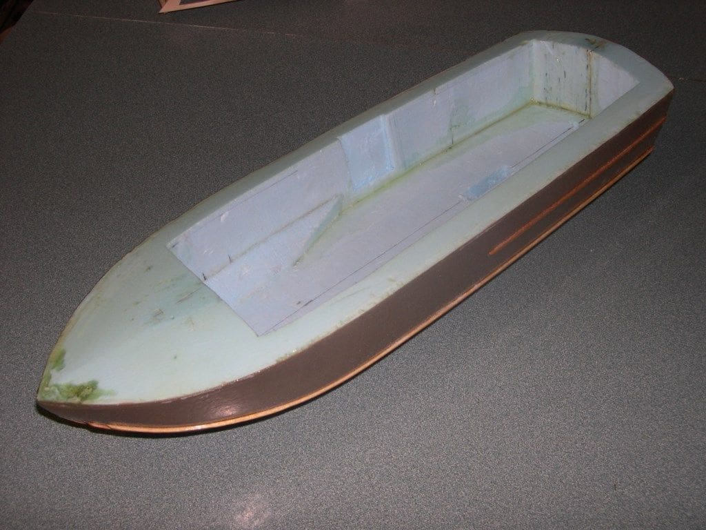
Fitting the hardware
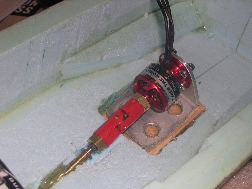
There is nothing magic here except to glue in place, using five minute epoxy, a thin plywood mounting plate for each unit of the internal running gear. These bases give a firm and lightweight base for each component. The tiny brushless outrunner motor was mounted on a scrap piece of aluminium angle bar with a few extra holes in the base to lighten it further and increase its gluing area. The internal foam part of the hull needed a sloping area cut away to get the propshaft, coupling and motor aligned. I bent a bit of stiff wire, taped it to an offcut of dowel so I could hold it, while it was heated with a blowtorch. This simple tool easily carved out the sloping area for the motor mount and once I was happy with the alignment, the motor base was epoxied in place. A small trough had been hollowed out of the foam where the propshaft came through the hull and this was filled with epoxy, making a nice strong joint. The battery location was determined whilst the hull was floated in the domestic bath test tank and two compartment walls of balsa were installed with a thin strip of wood that swivelled out of the way to hold it down.
As I was not sure which way round the motor would run until it was powered up, a three section piece of three amp lighting connector block was installed, so the wires could be swapped around if necessary. As it so happened, it was the right way round in the first place, but I left it that way as it looked neat and stopped all the wires flapping about anyway.
While on the subject of fitting out, I’ll never understand why propshaft suppliers rarely fit their shafts with an oiler point. I think it is essential that a bit of light lubrication is used when spinning dissimilar metal parts and water are mixed together and then left on the shelf for weeks on end. It’s so much easier to drill a 3mm diameter hole in the top end of the outer tube before the propshaft is installed in the model. Clean out all the swarf and soft solder a piece of brass tube into the hole, making sure it doesn’t interfere with the propshaft itself and you have a lubricator point.
Planking the decks
I had left the deck flat to help in the carving stages and to maintain an accurate datum to measure from. Now it was time to mark out the quite pronounced camber as used on these Huntsman craft and to trim the resin skin down to where it had to go. Careful marking out and the use of a permanent fine marker pen followed by firm pressure with a good sharp craft knife produced the line now needed to sand to. The original templates from the plan were used again for this marking stage and then the deck was sanded to its curved shape and down to the line using a flat plywood homemade hand sander with 80 grit decorator’s sandpaper on it.
Every now and then, stop and check and redraw the centre line to keep a eye on how much you are taking off. Once happy with the shape, I then had to consider how to plank the deck. Compound curves going in every direction are not easy and you can’t pin it to the foam or clamp it to hold it in place either. It had to be quick and easy to do, but spray contact adhesive or superglue would melt the foam. So, I decided to give the sanded deck foam a thin coat of twin pack epoxy resin. This would seal the foam and then allow the use of medium superglue over it to hold down the decking.
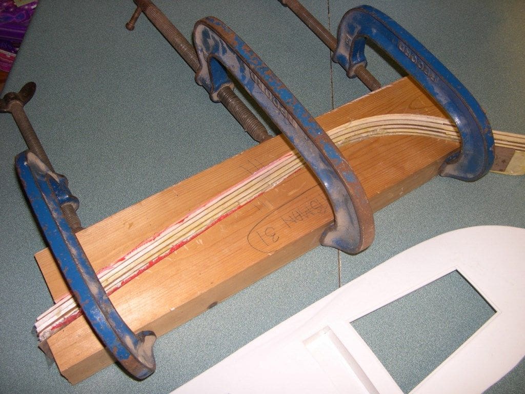
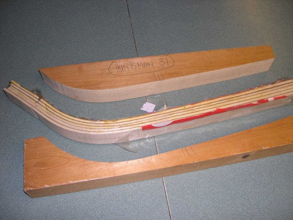
To obtain the bow to stern curvature of the decking as fitted on the real boats, I laminated-up a curved block of decking as had been done for the little ‘Diana’ in November 2011 MB, but this time there was a pronounced camber to contend with as well. I knew that sliced sections of laminated decking would not bend that way as well without breaking, so the solution was to use a really soft and pliable wood. There is only one which is the right colour and capable of the double curvature and that is good old balsa wood.
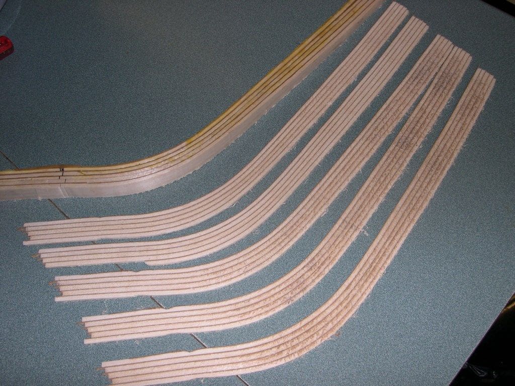
Some 3/16 inch balsa sheet and mahogany veneer was laminated using Aliphatic Resin glue, as this soaks very well into balsa wood. The pieces were then clamped into a curved wooden 4 x 2 inch pine former made using the deck templates. Once dry, it was slit it into 2.5mm thick pieces across the laminations, on the table saw. This thickness seemed to curve okay across its width, so planking began using medium superglue painted quickly on to the resin coated deck foam and held down by hand until set. A couple of mahogany king planks were fitted down the centre line. Once the whole thing was done, the overhangs were trimmed to fit the cabin, which had already been partly assembled as a guide, and the underside of the decking overhang inside the hull filled with a little fillet of five minute epoxy applied with the universally patented glue spreader (index finger) to strengthen it all up.
Once the deck outside edge was sanded flush with the sides, the mahogany deck edge rubbing strip was fitted and the whole hull given one last thin coat of resin before its final rub down in preparation for painting.
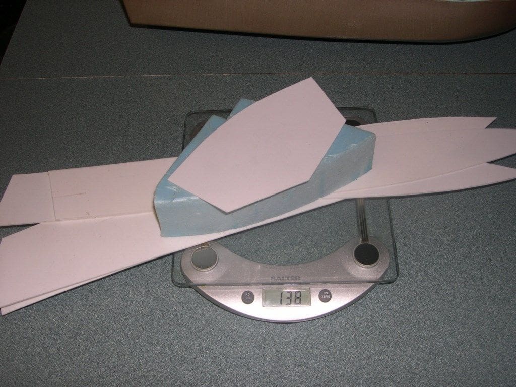
Comparing weights and measures?
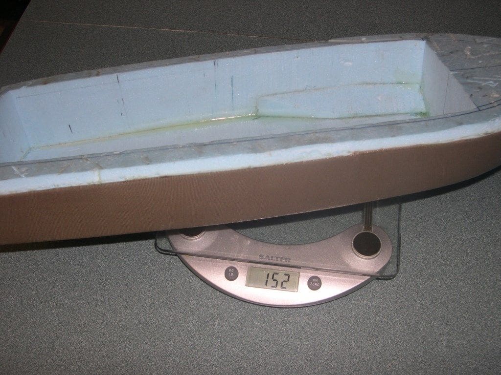
It was about this stage that I decided to compare what the weight of the styrene model hull would have been alongside the foam based hull. I collected together all the bits that I had cut out of styrene and weighed them along with a piece of foam I would have installed in the bow had I built the model as Richard Webb intended. Without any glue or filler it came out at 138 grams, that is about 4.5 ounces in old money. The foam, stocking and resin coated hull came out at around 150 grams which is about 5 ounces, but it is inherently stronger and totally unsinkable, unless you put a brick inside it. In fact, the almost complete hull weighed less than a small bag of sherbet lemons – my favourite from school days!
The brushless motor was less than a quarter of the size of the 400 type brushed motor recommended and the LiPo battery pack (3s 11.1v x 2200) was more powerful and less than half the weight of the Sub-C NiMH 7.2v x 1800mAh that would have been used to drive the conventional motor. All of this told me I could go ahead and add a bit of extra detail on the cabin top. In any event, I had planned to make all the bits myself and keep everything as light as possible. These models must be kept light because they should be capable of a surprising top end speed, but also be manoeuverable at slow speed as they were after all based on the Round Britain Powerboat Race winners.
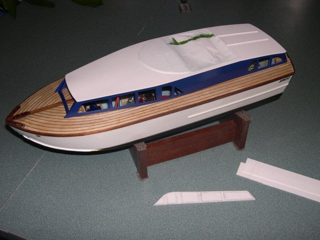
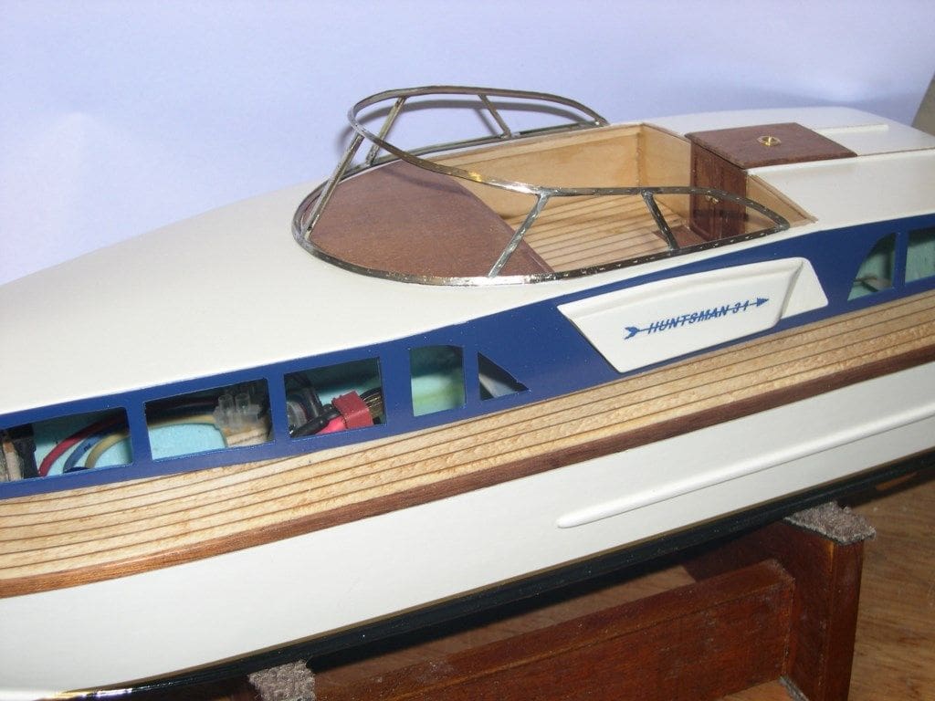
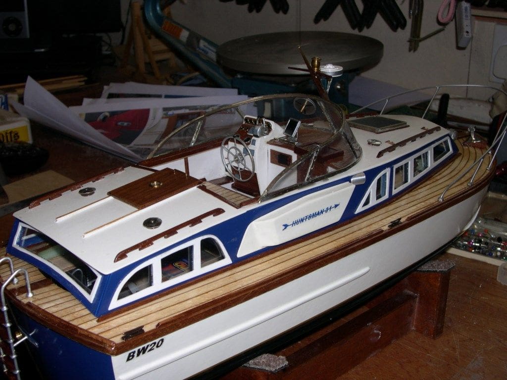
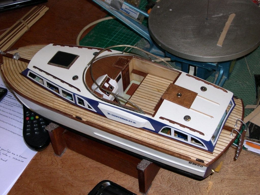
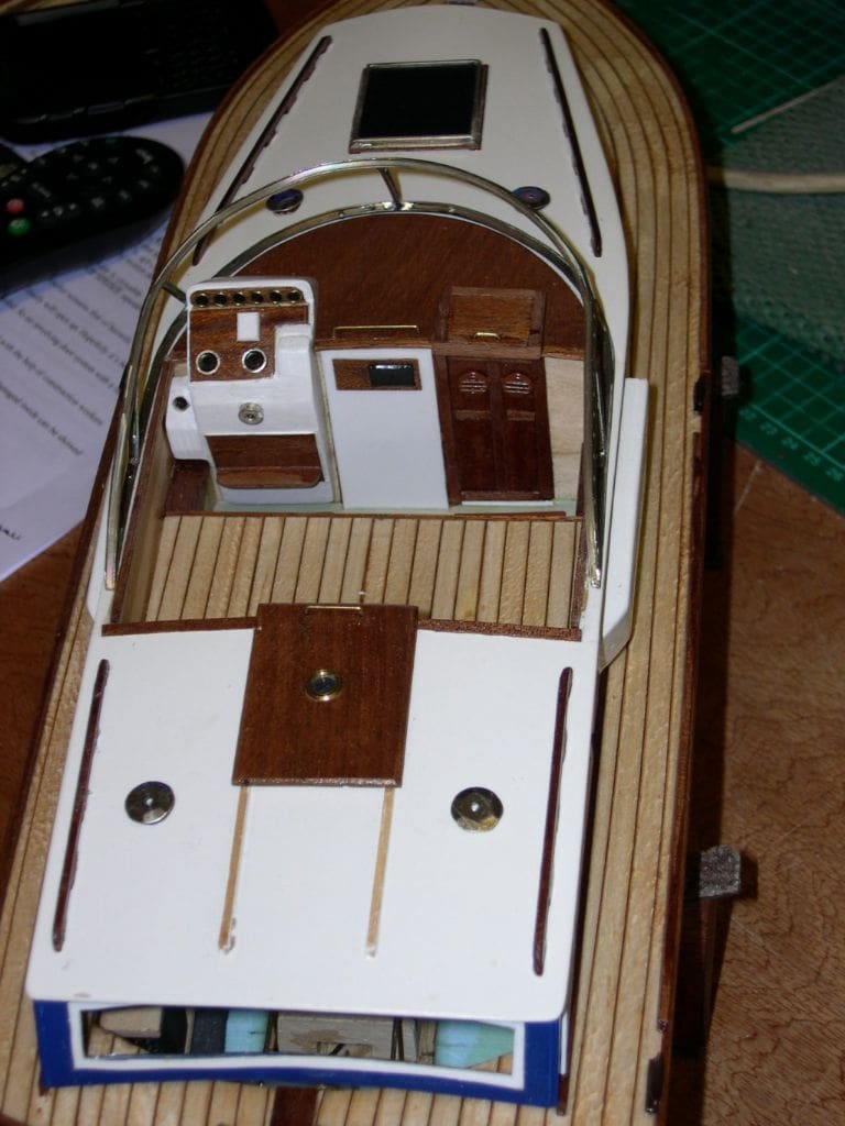
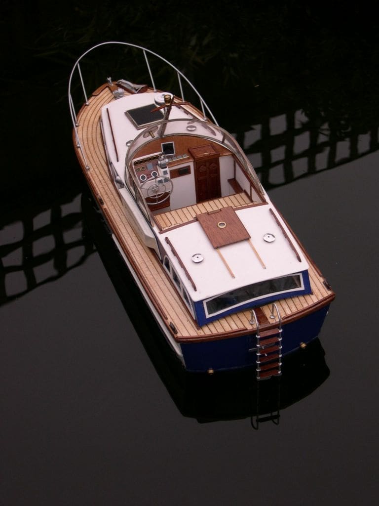
Cabin, cockpit and fittings
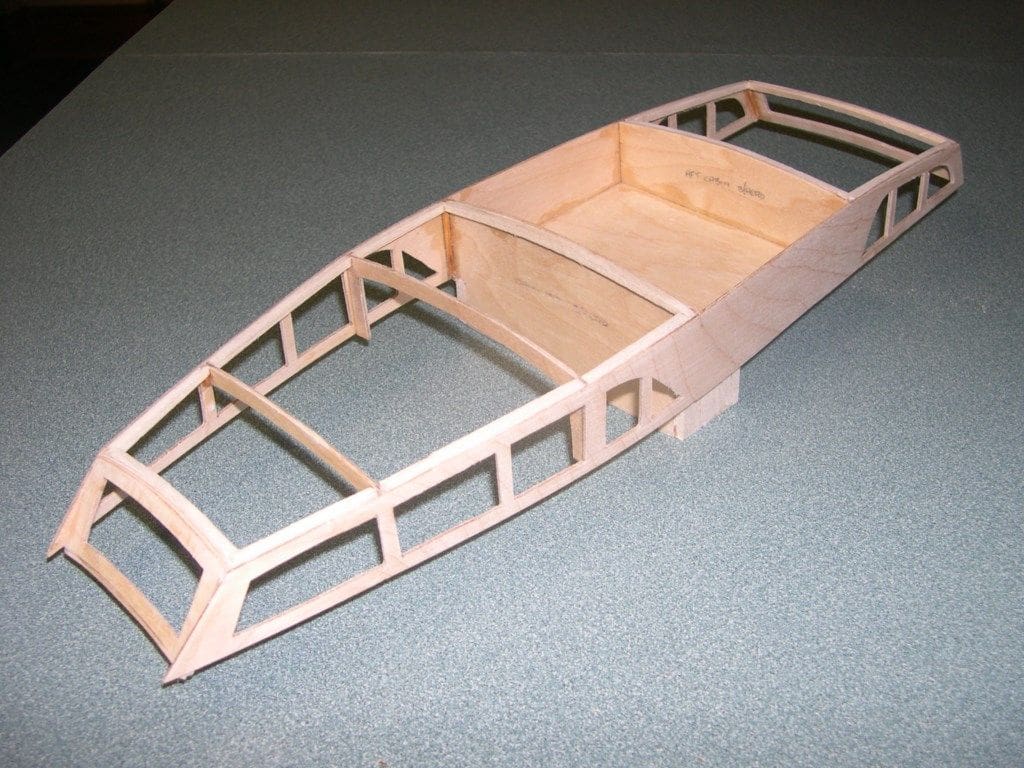
The cabin construction is basic and straight off the plan. I chose to stick to my favourite material of wood instead of styrene, although I did make the window frames out of 1mm styrene which proved a pain as I should have used 0.5mm which would have been easier to cut. Most of the upperworks are 1/32 and 1/16 inch plywood with 1/8 inch balsa strip to strengthen corners.
Mahogany was used where the real boats had it, namely for the doors, capping strips, handrails and so on, all of which was cut down from larger pieces, usually scrap. Woods like this are very expensive to buy nowadays and I grab whatever I can find if it is free and put it into stock.
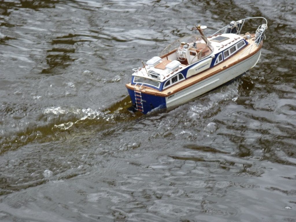
Making good use of the many pictures on the the Fairey Owners Club website, I endeavoured to replicate as much of the deck hardware as possible. Balsa was carved for the console with ‘jewellery jump rings’ for the dials ( from Hobby World, art and craft shops). The CQR type anchor was made from brass, together with the winch, towing pulley and other rope fittings. A pack of 50 tubular foam darts found in ‘Toys R Us’ made the long straight floats and fenders and the round fenders are just cork ball floats from the fishing tackle shop. These were all encased in AA size heat shrink tubing, the tops formed by squeezing the plastic closed while hot, then drilling and shaping. The wire stowage cages have yet to be made….
This is the most enjoyable part of modelling for me and I can happily spend a day making a tiny fitting such as a steering wheel, so yes, my wife thinks I’m mad as well!
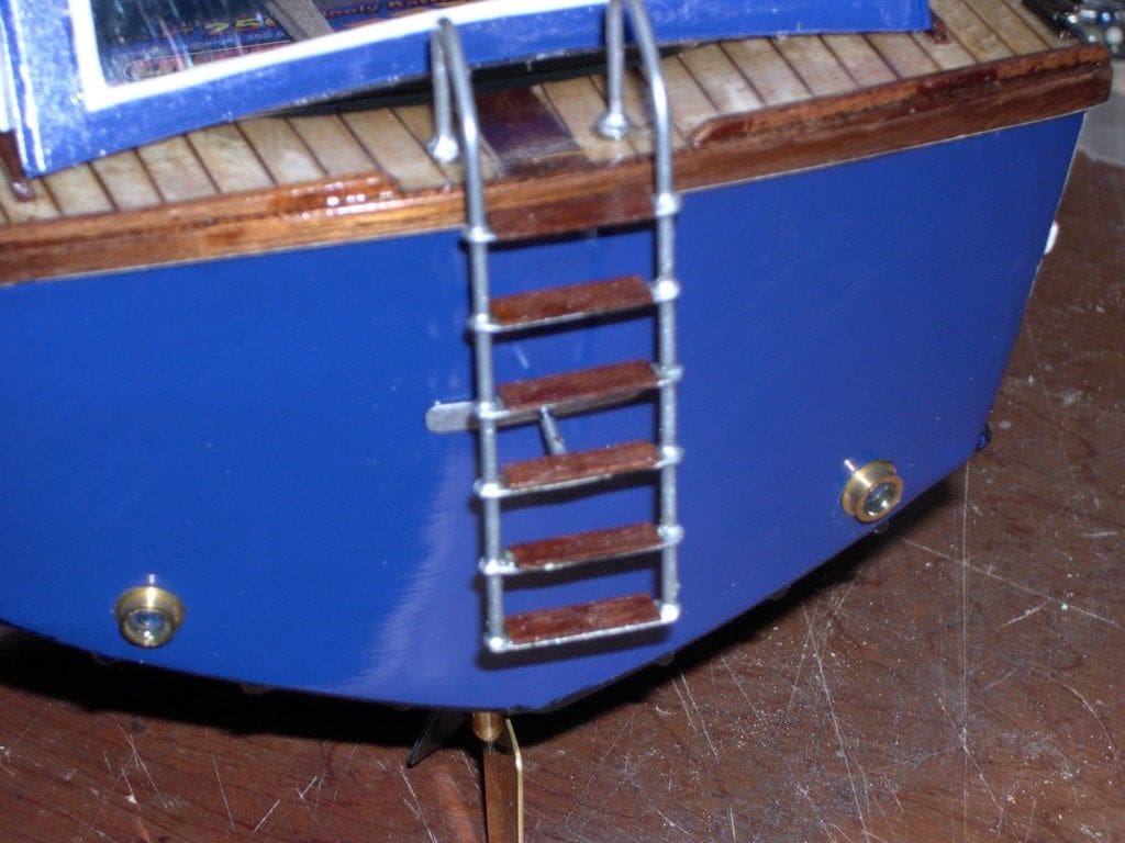
Fishing tackle and haberdashery shops are great sources of items that can be adapted for our models and usually at a fraction of the price of a ‘proper’ fitting. For example, the ventilator covers are chrome sequins and cost £1.95 for 500, and yes, that is not a mistake! We all use copious amounts of brass wire and buying 300mm lengths from model suppliers can cost a fortune. SIF bronze welding rod (Spelter) from an engineering shop has proved ideal for most of the handrails and ladder rails. It comes in various diameters, polishes and solders beautifully and is in three feet lengths. Usually you buy it by weight and 20 lengths cost me barely £3.
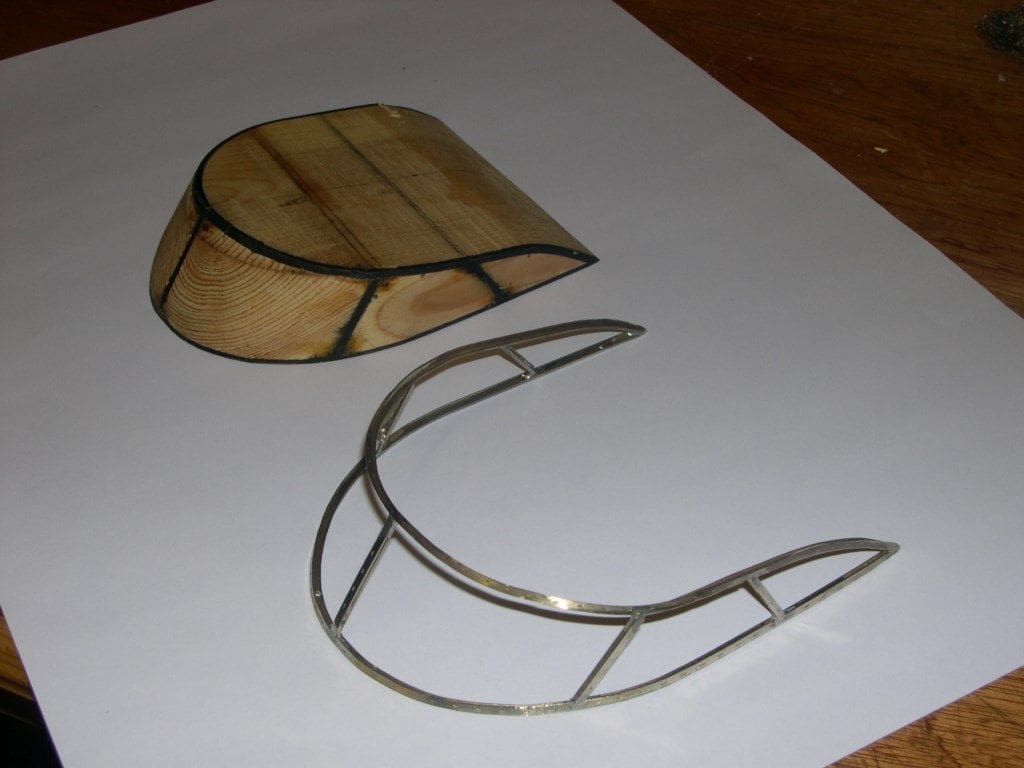
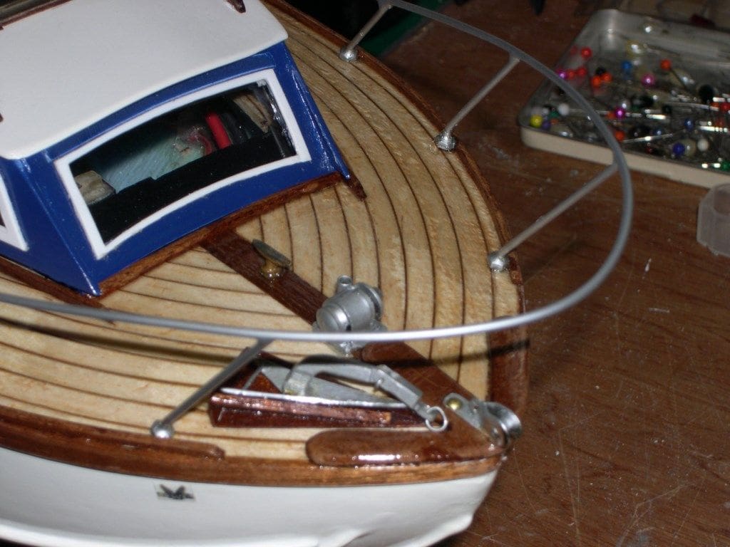
A proper windscreen?
One design aspect that stands out on these Fairey boats is the curved windscreen. It defines the look of the boat and according to one full size boat owner I have spoken to, they now cost more than a small family car to replace!
Models are often built with just a piece of clear plastic bent to shape, stuck on with a smattering of trim tape round its edges. A close look at the real thing will reveal a substantial stainless steel or aluminium H channel frame, often with mahogany inlayed into its top edges, small hand holds, navigation sensors, mirrors, radio masts and so on, all attached to it at various places, depending on any upgrades the owner has made.
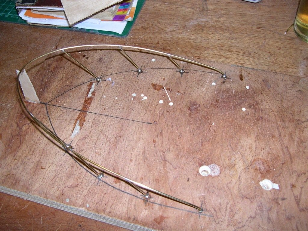
I wanted to replicate this quality product if possible and began looking for a suitable material. It had to be the right section and in lengths long enough to form the two main curved rails. Some OO/HO gauge flexible railway track in Model Zone was spotted which was over three feet long and very bendy, so a length was purchased for £3.95. Throwing all the plastic track ties into the spares box, I was left with two pieces of metal strip of the exact profile required. This was an H section and made from what I can only assume to be an alloy of tin and nickel, so was unlikely to rust.
A simple pattern shape was drawn on to a piece of pine, cut and sanded to shape so it sat neatly over the fixing area on the cabin. The railway track piece had to be annealed before it could be bent round the pattern. This was then pinned in place and the smaller angled uprights cut to size with a location tab on their ends to fit into the channel. A fiddly task, but not difficult. A dab of flux paste and a second with the small gas blowtorch soldered all the joints and the frame was taken off the pattern block for cleaning with needle files and wire wool.
It certainly looks right when in position and clear acetate pieces cut from stiff, but thin, Easter egg packaging just snap into the channel without messy glue. The top exposed channel was filled with mahogany two part wood filler paste, sanded flush with the metal before varnishing, thus finishing the windscreen just like the full-size versions.
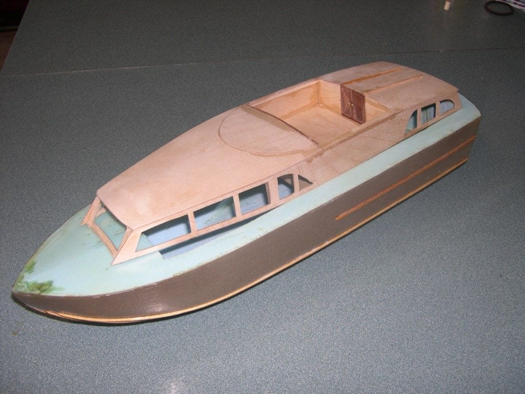
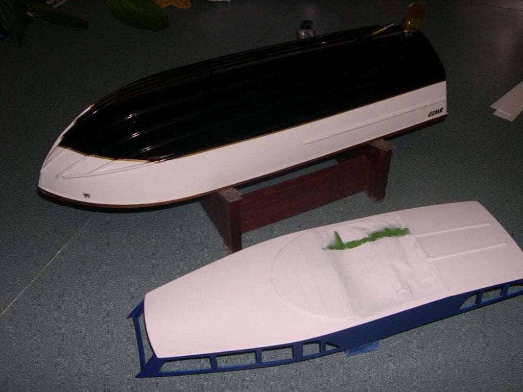
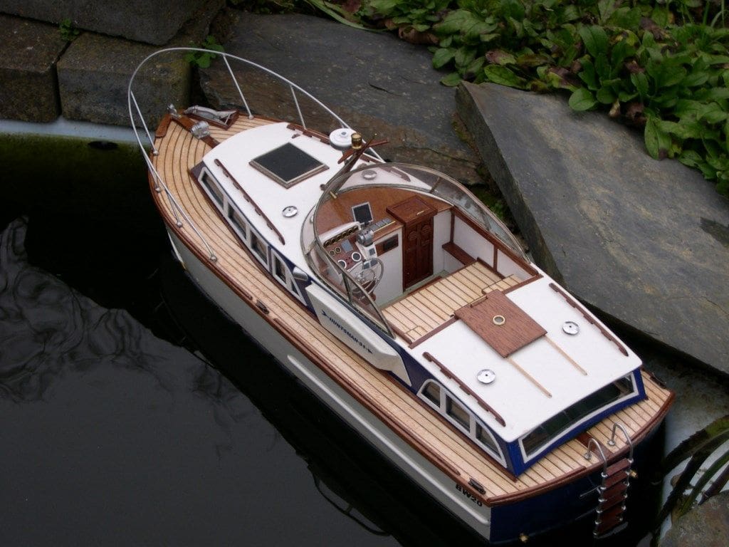
Painting and finishing
After masking the pre-varnished wood areas, all other parts were sprayed with Halfords white primer with a fine wet and dry sanding between coats as needed. Ford Diamond White, Fiat Dark Blue and Gloss Black acrylic spray paints were used for the main colour scheme. Gold trim for the waterline is actually of paint that comes sandwiched between two layers of removable plastic and this comes from a specialist car paint and trim shop. This stuff is expensive, but it is not a sticky decal tape and it looks so much better and will not peel off when handled or repeatedly immersed in water.
All the fittings were hand painted or sprayed before fitting and the whole model given a thin spray of gloss polyurethane varnish for final protection. Don’t use too much of this as the white paint will start to ‘yellow’ after a short time. The clear screens were fitted after final varnishing.
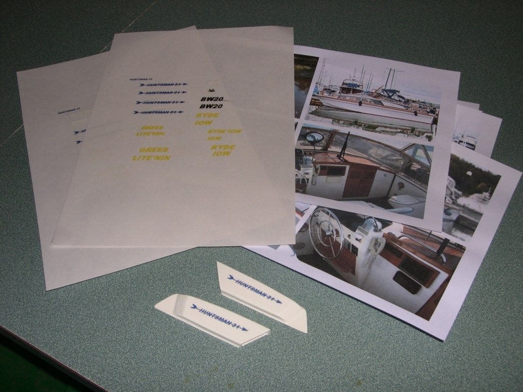
Making your own decals
The fine lettering was made using Windows Paint (found under Accessories in the software). This is a very simple CAD program that most people don’t even know they have. It is easy to import images like the Fairey Owner’s Club badge and reduce them down to grain of rice size if needed. Lettering is easy to do and you can slide them around to get the layout needed. A dark print stuck over white paintwork works best. They were all printed, for checking, on plain paper first and then on Letraset Safmat self-adhesive printing film, available from PC World or Rymans. These were then cut out, peeled off and stuck on to the model, but don’t hand paint varnish over them though, as they will smear. Lighter coloured lettering over dark surfaces is better done with the conventional dry lettering which can be lightly varnished or sealed with Humbrol Decal Fixer.
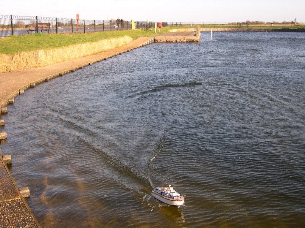
Maiden voyage
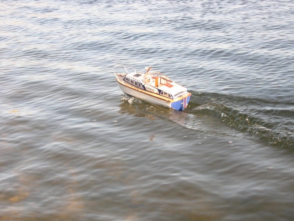
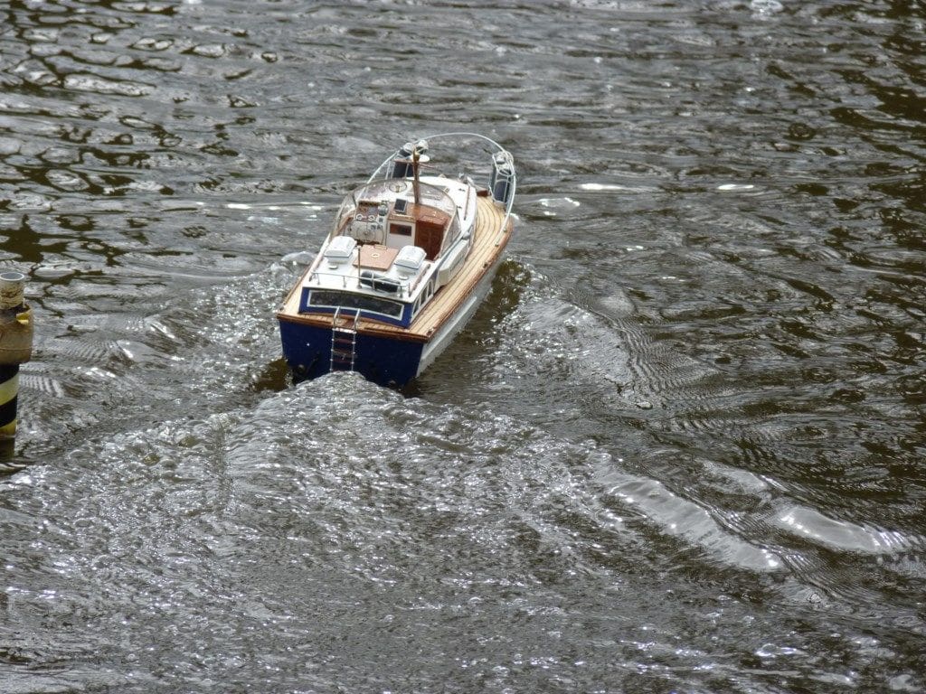
The weather had closed in just as the model became ready for trials and even our local lake was frozen solid. I had to wait till things got better before I could fully test out the model and take some on the water pictures. Whilst visiting an old aeromodeller friend in Essex, he took me and the model to the Promenade Park Boating Lake at Maldon where it was a nippy, but bright and sunny day. Only a 2s 7.4v LiPo pack was installed, a bit smaller than the 11.1v size planned, but adequate for a slow run round and shakedown first outing, or so I thought……. The propeller was a normal nylon 35mm diameter version with a standard pitch. The propshaft was well oiled since Maldon is salt water. A few clicks forward on the throttle stick, and?
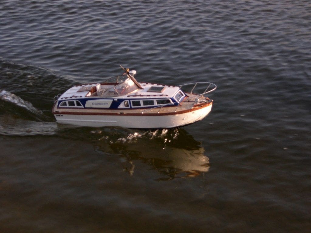
Yes, at quarter throttle it lifted straight on to the plane and tore down the pond like a rocket! I thought something had gone wrong, but all was well. It was just so unbelievably fast, but handled remarkably well. Increasing the throttle and the model just went faster and faster leaving only about two inches of hull in the water and this was where it all went wrong.
Without thinking, and as the model was getting a very long way away, I tried a full speed turn to bring it back which was a very bad mistake!
Have you ever seen one of those pineapple corers and peelers, well that is what it did. Right over on its side into a really tight circle, the cabin even though designed not to, came flying off and the hull plunged under the surface for an instant before leaping vertically out of the water like a dolphin. My mate, who was watching from next to me, made a loud expletive to which I concurred. The hull is unsinkable and it all seemed to be still working for a somewhat slow return to the pondside, but the cabin took another 20 minutes to drift in.
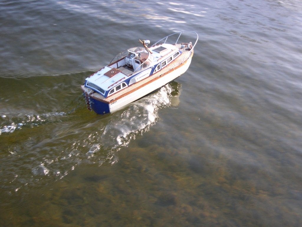
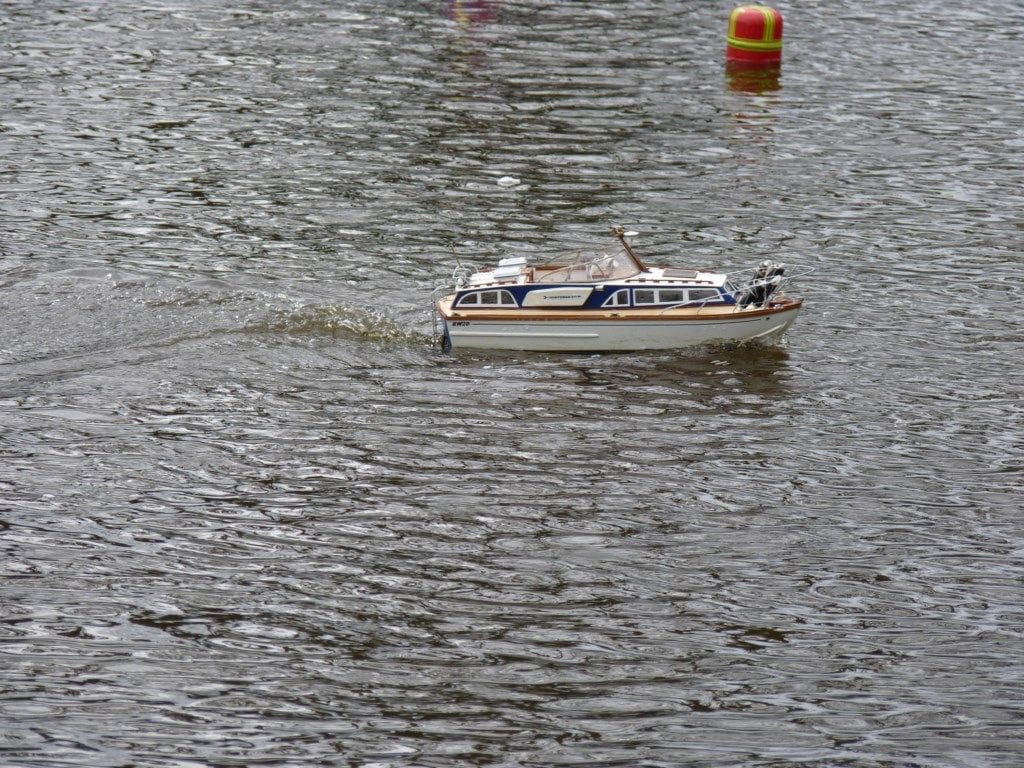
Some water came out when the hull was inverted, but everything was still working okay, so we slowed it down a bit and took some pictures. Back home, the r/c gear was cleaned and allowed to dry naturally and the hull washed in lukewarm fresh water as another soaking could do no harm after this day’s adventures.
The next day, it was tested and found to be fine, but the rudder throw was reduced by half of its travel and about 5mm was cut-off its blade’s back edge as well. At about 525 grams all up (just over 16 ounces) it was obviously too light and needed some ballast which was added from assorted pieces of 6 x 50mm scrap copper plate. A further trial and sensible throttle use has now tamed the model.
Conclusion
Back in the 1960’s when building big heavy models for radio and straight running at the Victoria MSC in Hackney we used to say, ‘You can never have enough power’ and I suppose at that time the statement was true. We only had access to lawn mower and moped two stroke engines apart from the Gannets, Seals and Channel Island Specials which were out of our financial range. We built boats to last, to carry giant reed radios, 12 volt car batteries and withstand the rough handling they got in competitions. So strong and heavy were they, that even 50 years later a lot of them are still around and are passed down to children and grandchildren, also being displayed proudly on the VMSC and Blackheath club stands at shows. Nuclear age models built to withstand nuclear warfare, if you think about it.
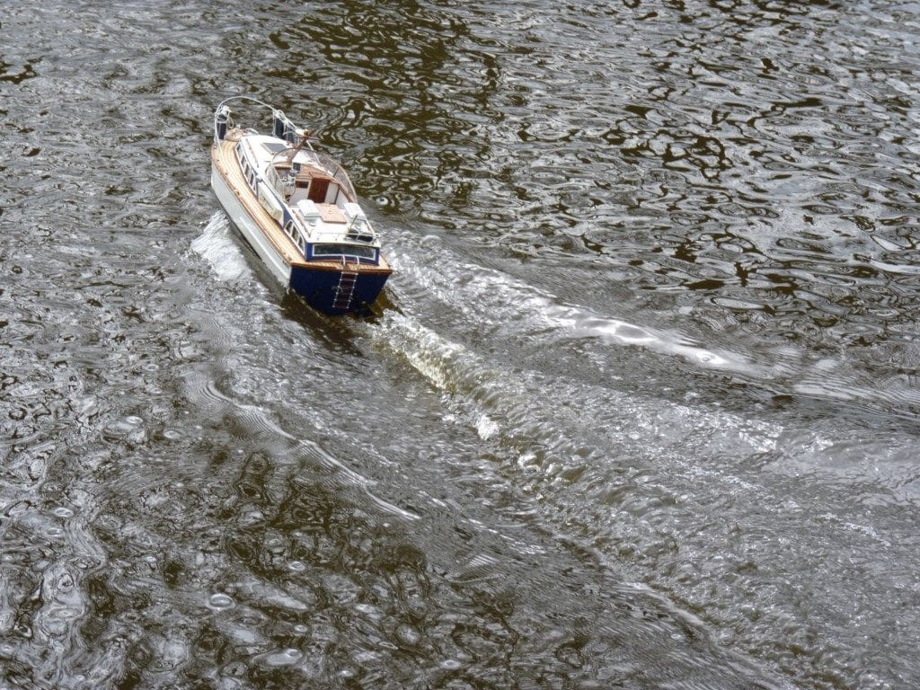
Very few of the things we have today existed then, such as miniature 2.4Ghz r/c, epoxy resins, foams, superglue and of course brushless motors and LiPo batteries. This little Fairey Huntsman is horrendously overpowered if the truth were known, but it is a super lightweight model with a technologically superb and very powerful motor set-up, even though it’s small size would make you believe it couldn’t be powerful enough. Even with the Tx dual rates switched on, it hits scale full-speed attitude on the water at only a quarter throttle. I’ve now got ideas for another one, foam again and maybe even twin motors, but smaller. All in all, this is a great fun model and I look forward to many more exciting spins round the lake.

