This release by Billing Boats is a rather unusual subject for this long running boat kit manufacturer – it’s a model of the American Speed Record Holder from the 1950’s era, called Slo-mo-shun. When three men met in 1949 at a Seattle marine shop, not one of them could have foreseen the future and far reaching dreams of their joint venture, to build a world speed record boat. Slo-mo-shun IV touched the hearts of thousands who cheered her on, and changed forever the way generations of Seattleites felt about the Slo-mo-shun IV. This was the period of 1949-1952 when the water speed record was held by an Englishman, Sir Donald Campbell, with a speed of 141.74 mph. Stan Sayres, an automobile salesman from Oregon, had made a number of trial runs in Slo-mo-shun during late June, and then in the early morning hours of June 26th lake conditions were excellent. On the first attempt the timing system malfuctioned, so after continuing to the south end of the lake, the next run produced 163.785mph. To create a record the rules required a further time in the opposite direction within a 15 minute period. This was timed at 157.2mph, giving a combined average speed record of 160.3235mph, announced in the morning press. Then, a further attempt on July 7th resulted in an increase to 178.497mph. This record was to stand four years.
Article continues below…
Enjoy more Model Boats Magazine reading in the monthly magazine. Click here to subscribe & save. The full size boat was built by the Jensen Motor Boat Company and launched in mid October 1949. She was made of a shell of marine plywood mahogany panels, 1/2in on the bottom and sides, and had a 3/16in deck and a superstructure of oak and spruce with aluminium cladding on running surfaces and aircraft type fittings of forged steel hardware. Her dimensions were 28ft length between perpendiculars, a 2ft 6in depth of hull in the centre section, with a beam of 11ft 6in and a dry weight of 4,4001bs.
|
|
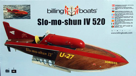
The KitThe model is produced at a scale of 1:12 giving an OAL of 29 1/2ins with a beam of 12 1/4ins and a height of 8 1/2ins making an it excellent size for transportation. A shot of the model on the water on the box lid can be seen in Photo 1. The model is a wooden boat builder’s delight. The contents of the kit are shown in Photo 2. The main wood is plywood and the frames and building frame are laser cut. Included in the kit are wood strip planking, thin veneer strip, an ABS vac-formed top moulding, a set of plastic fittings, a propeller and running gear, a set of instructions and a superb set of decals. Also included is a resin-cast driver’s seat, and a full size set of drawings, which can be seen in Photo 3. Building the ModelFirstly the frames and the building frames need to be cut out from the laser cut sheets. This is a straightforward task achieved by cutting the small tags on the wood to release the frames required and the parts cut out with a craft knife, as can be seen in Photo 4. It must be stated that the next operation is probably the most important thing to get right. The cut-out building frame must be mounted on to a perfectly level building board. 1 used a piece of Contiboard with no warping. By drawing a perfectly straight line in the middle of the building board, the frame was laid and supported by a number of small blocks of wood which held the building frame in place, see Photo 5. Next the frames were glued into position, making sure with the help of a small set square that they were perfectly vertical and square to the frame. This can be seen in Photos 6 and 7. All the wood parts during the building were glued together using R/C Modellers Craft Glue from Deluxe Materials which can be obtained from Scoonie Models and all good model shops. The stringers were added to the frames, which gave support to them and the planking. The fitting of the stringers can be seen in Photo 8. Also the two side skins at the forward part of the hull were fitted.
|
|
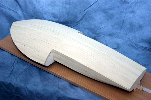
PlankingNow we came to the main planking; this needs to be done while the building frame is still fixed to the building board. I started with the full lengths and worked from the centre of the hull installing planks equally both sides so as to prevent any twisting of the hull during planking. This process can be seen in Photos 9 and 10. The planking continued until all of the top part of the hull had been planked, including the sides. At this point the building frame is still fixed to the building board, and now needs to be released. Photos 11 and 12 show the planked hull top after being released from the building board. The building frame now needed to be cut away from the hull so that the hull bottoms could be installed. This is shown in Photos 13 and 14 and was done with the aid of a hacksaw blade, as each frame had to be cut away from the building frame. This left the bottom of the hull to be covered with pre-cut plywood panels both for the stepped hull and the main hull bottom, not forgetting to cut out the opening for the prop shaft. Both the panelled bottom and the planked top can be seen in Photos 15 and 16 with an access panel marked out on the top. Photo 17 shows the hull with the access panel cut out and the rear fin temporarily fixed in position. Motor and PropshaftAt this stage of the building I decided to install the motor and propshaft. It was recommended in the instructions that a Speed 600 be installed. I added a Huco coupling to the supplied shaft, tube and propeller. The motor and shaft installation can be seen in Photos 18 and 19. Also at this stage I decided to install the rudder and servo; the instructions indicated that the servo be installed prior to the planking, which meant that one could not gain access to the servo once the planking was complete, so I decided to install it with a small access panel for future maintenance. The push rod and rudder were both temporarily installed at this stage as seen in Photo 20.
|
|
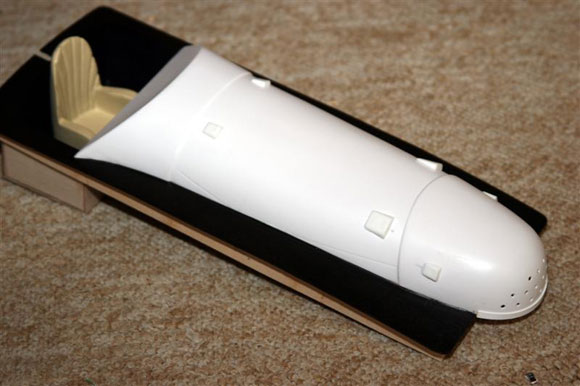
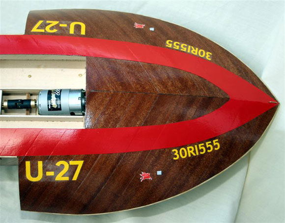
Cowling and Veneer PlankingBefore starting the veneer planking I constructed the engine cowling to fit the access in the hull top. The cowling was a one-piece ABS moulding mounted on a wooden plywood base and all made to fit perfectly before starting the veneer planking; this can be seen in Photos 21, 22 and 23. A bundle of veneer planking is provided in the kit and is more than enough to cover the hull. Marking a line along the centre of the hull top I started to mark in pencil the correct angle required for the whole length of the hull including the side parts. Starting in the middle of the forward part of the hull and then working towards the front and then to the rear, the veneer was fixed to the planking, again using R/C Modellers Glue, a PVA based glue. After all was dry I cleaned up the edges with sand paper. All this process can be seen in Photos 24 and 25. One tip when cutting the veneer strip is to use very sharp craft scissors, as cutting with a knife tends to split the edge of the veneer. With the whole of the veneer strip complete and dry, a rub down with some fine sand paper is all that is needed. Just to seal the veneer I applied a coat of matt Humbrol varnish as this would protect it from any accidental marks during the finishing of the model prior to final painting and varnishing the hull. The engine cover as previously mentioned was an ABS moulding on a plywood base, and this item could be completed with the addition of the exhaust pipes, cockpit instrument panel and the driver’s seat. The exhausts were made from wooden dowel as supplied and the instrument panels and gauges were decals, which were also supplied. The finished cockpit was sprayed with gloss paint and then with two coats of gloss varnish, the same applied to the painting and finishing of the tail fin, with the decals being added before the final coats of gloss varnish. See Photos 26 and 27. PaintingPainting of the hull consisted of a large red stripe running from the bow to the transom in an arrow design. This was done by marking out the hull with masking tape and then spraying with red Humbrol gloss paint, being very careful not to over run on to the veneered parts. As previously mentioned a small hatch cover was made to gain access to the rudder servo; this can be seen in Photos 28 and 29. The bottom of the hull was painted in a steel grey colour and given two coats of satin varnish to seal and waterproof the hull bottom as in Photo 30. The fin was the next thing to install, glued and pinned to the rear deck using 24hr Araldite glue, Also prior to final varnishing the decals were attached together with the fittings supplied with the kit, i.e., petrol tank covers, ventilators, etc. When complete the whole of the model was given four coats of Humbrol gloss varnish, carefully rubbing down between each coat. Decals and finish can be seen in Photos 31 and 32.
|
|
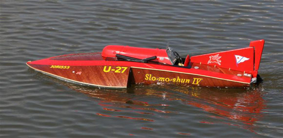
R/C InstallationNow I came to the radio control installation which can be seen in Photo 33, bearing in mind that this is my way of installation. The variations of equipment and design will vary from modeller to modeller. I used a Hi-Tec two-channel radio, one channel for steering and the other for motor control. The batteries were of the car racing type and the speed controller was the Hi-Tec Pro EZX-R reversing speed controller with a forward peak current of 140 amps. On the WaterWith the model now complete it was time for its maiden run. With the battery fully charged the model gave a stunning performance with exceptional speed and quite a good turning response. With a little better trimming which brought the bow up, to stop the digging effect, it performed a lot smoother on the turns. ConclusionA great kit for anyone who likes building with wood, and with the laser cut parts everything fitted perfectly. Care needs to be taken with the veneering but it’s a great choice of subject and great value for money. If you fancy something different try the Slo-mo-shun IV, it will look good on the water or as a static model. The price is around £100.
|
Slo-mo-shun IV
by
–
Advert
Enjoy more Model Boats Magazine reading every month. Click here to subscribe.
Article Tags:


