GARETH JONES builds something a bit different
Nessie’s origins are rather unusual for a radio controlled model. She started life as the subject of a bet between my wife Elizabeth and Sean Stewart, a freelance photographer who occasionally visits Goole MBC to take photographs for local and national newspapers. The subject of the Loch Ness monster came up in conversation in June 2013 and Sean said that if we could build a radio controlled model of it, he would come to the pond in his kilt and play the bagpipes. Coincidently the current issue of Model Boats magazine included an article on using foam in model construction (Ron Rees – Away with the Faireys, in the July 2013 issue) so we had some ideas on a potential building material and the project was commenced.
Propulsion and control – the power unit
Enjoy more Model Boats Magazine reading in the monthly magazine.
Click here to subscribe & save.
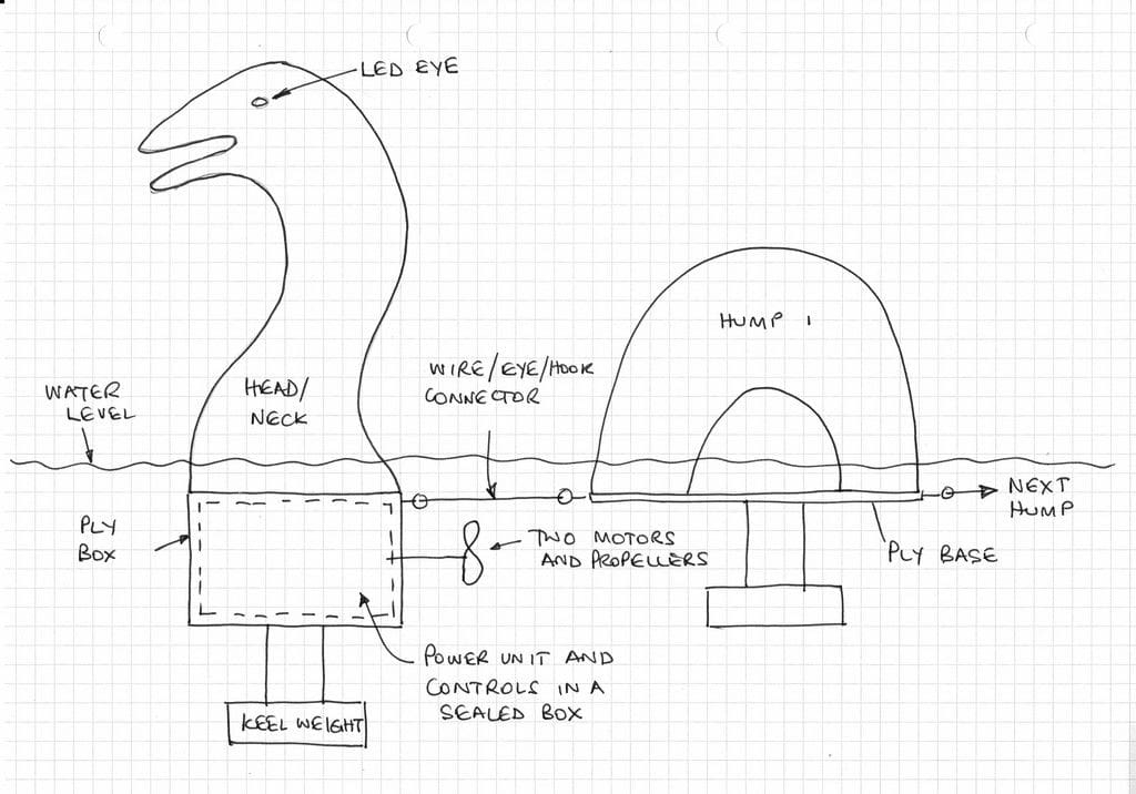
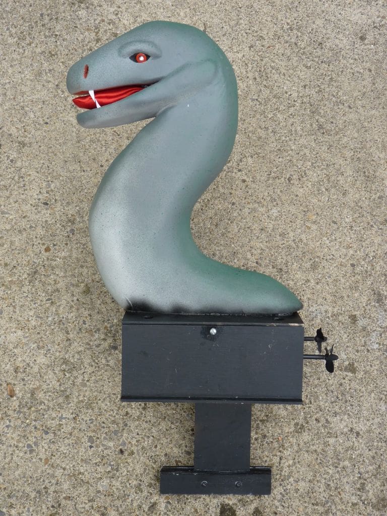
We saw a model of the Loch Ness Monster at York MBC some years ago and it had lingered in the back of our minds as a potential fun project. From our memory of that model, the most difficult aspect would be to make the propulsion and control system compact enough to fit in Nessie’s body, be leak-proof because it would be under water, but accessible for easy installation and removal of the battery. No problem you might say if you build model submarines, but a bit of a challenge if you have never tried it before. I started by sketching out some ideas and Nessie took shape as shown in Photo 1.
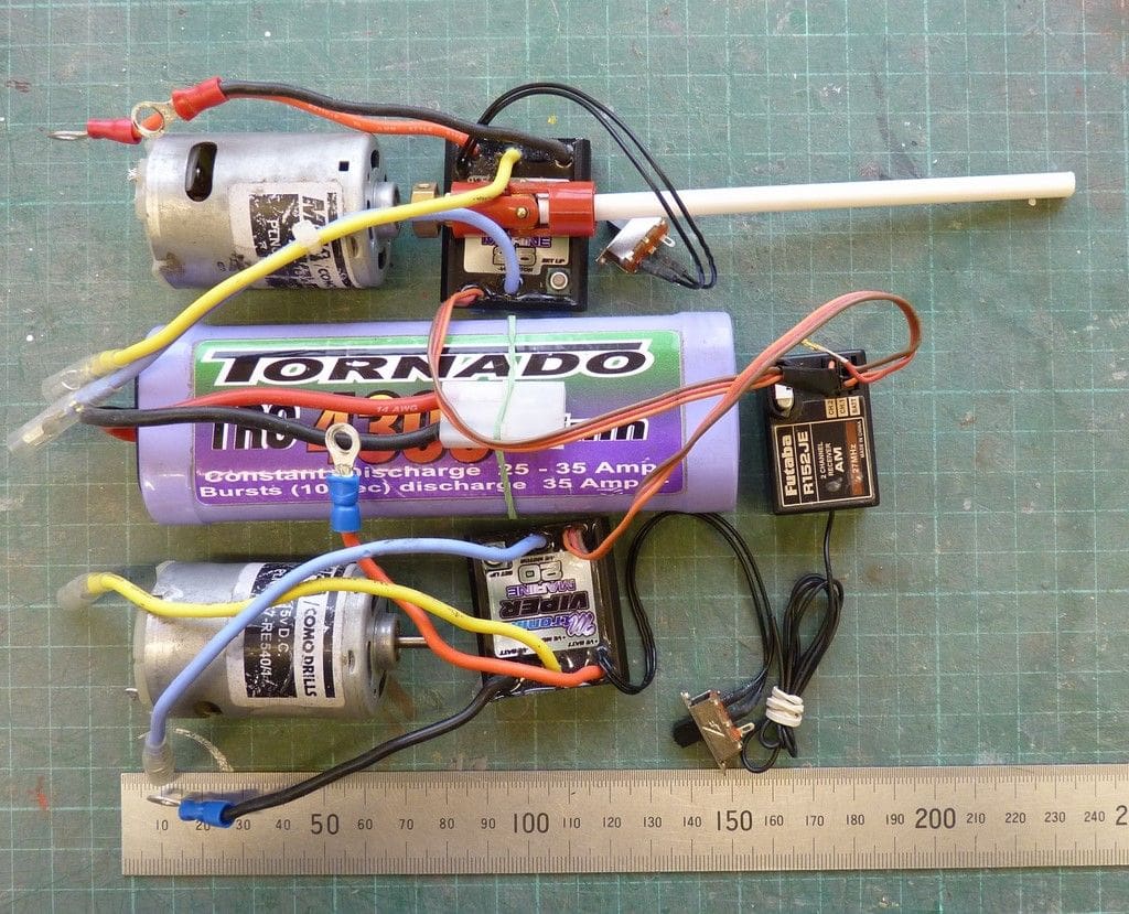
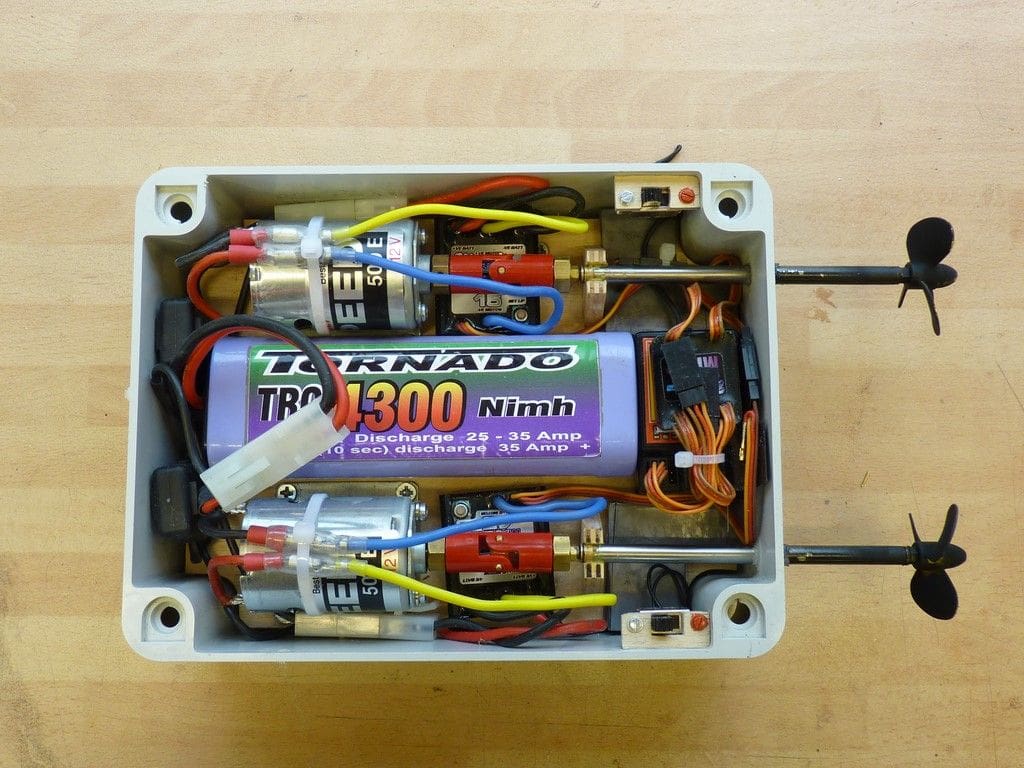
Making an accessible, but watertight compartment at home in our workshop would be difficult, but I knew such things exist for electrical equipment and a tour around, amongst others, the B & Q website revealed that an IP65 rated enclosure might well be suitable. IP65 is an international standard for Ingress Protection of mechanical casings and electrical enclosures. The 65 indicates that the enclosure would be dustproof and proof against ingress by water jets from any direction. The propulsion system had to fit in a fairly small space under Nessie’s head and neck and my initial thoughts were to use two 500 sized motors with a mixer unit to provide directional control. This had the advantage that the overall length of the unit could be kept short, since there was no need to fit rudders behind the propellers and the number of potential leak paths was reduced, since there would be no rudder pivots in the watertight enclosure. I had a couple of suitable motors, so I tried out various layouts on the bench until I came up with what looked the most compact option, Photo 2. I did briefly consider other options such as Schottel or Voith Schneider drive systems, but in the end I decided to stick with components I had in stock and probably more importantly, those with which I had some experience.
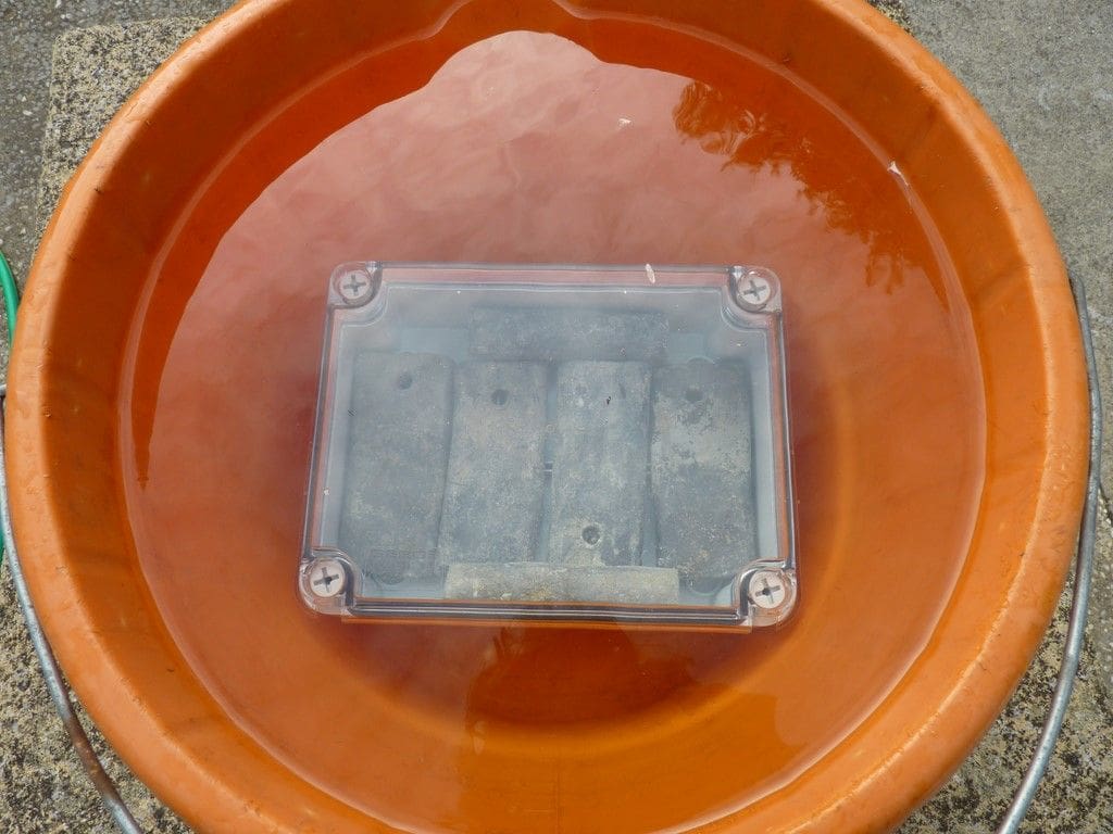
We were going to need a box around 200mm long, 150mm wide and 60mm deep to fit everything in and a hunt around the B & Q shelves of our local store actually failed to find the suitable enclosure. However, Maplins had a range of IP65 rated enclosures on their website, so a suitable box was chosen and ordered (Maplins order No. N09GJ) . These boxes have a clear plastic cover, sealed with a rubber O-ring and secured by four large countersunk plastic screws. The first step was to make sure the enclosure really was watertight, so it was filled with a few lumps of lead and left overnight in a bucket of water, Photo 3. The following day the lid was removed and apart from a small amount of condensation on the inside of the box, it was completely dry, which was a promising start.
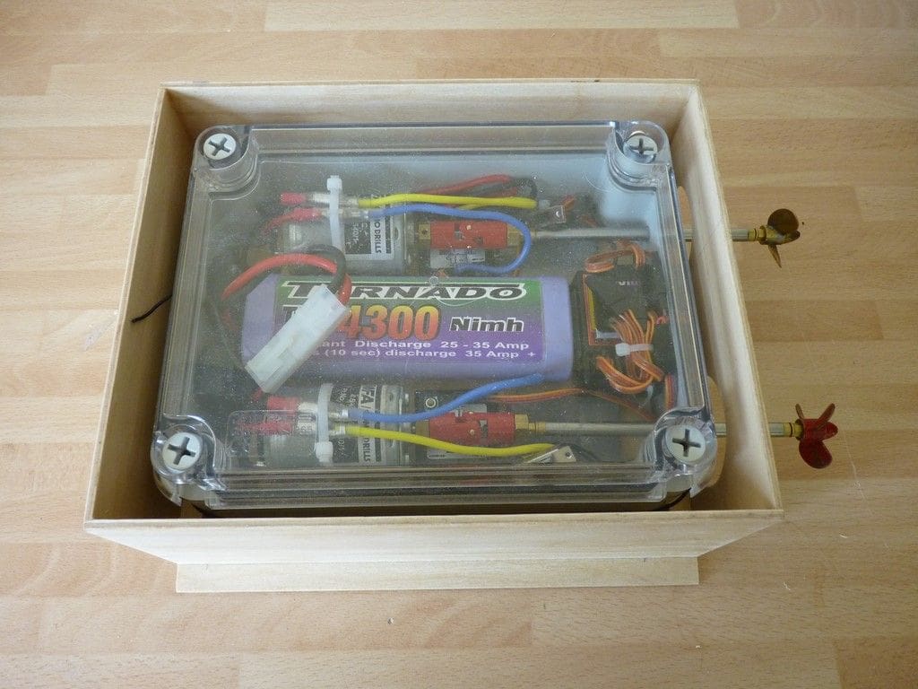
A 3mm ply floor was fixed to the bottom of the enclosure using countersunk screws. The box has a number of suitable attachment points on the inside and outside which can be used without piecing the box itself. All the components were fitted, basically as in the original layout on the bench, using Velcro for the speed controllers, battery and receiver. The radio receiver was mounted at the rear of the box with the mixer unit on top. Since 2.4GHz systems will not work reliably underwater, a 40MHz receiver was used. For the initial trials, the aerial was just coiled around inside the box.
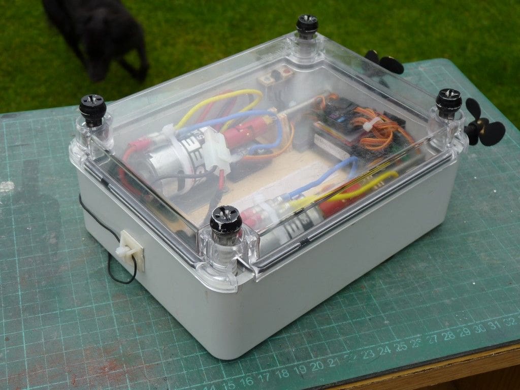
Two 15 amp Mtroniks speed controllers were used together with an Mtroniks W tail-mixer. Each speed controller is powered from the same 7.2v battery via a 10 amp fuse. The motors I had in my spares box were MFA Part No. 457-RE540/1 which had been rejected from a previous project as being electrically noisy, despite being suppressed. However I thought they would be adequate for Nessie, driving 30mm three bladed propellers via 100mm long propeller shafts, which were the shortest I could source. Subsequently I spotted a pair of Graupner Speed 500E motors on a supplier’s stand at Haydock Park and snapped them up as they are pretty difficult to find nowadays. These were substituted for the MFA units and now each drives a 40mm three bladed propeller, Photos 4 and 5. This is the combination we have in our 1:12 scale narrow boat and springer tugs and I find it works quite well for low speed models.
First pond trials of the power unit
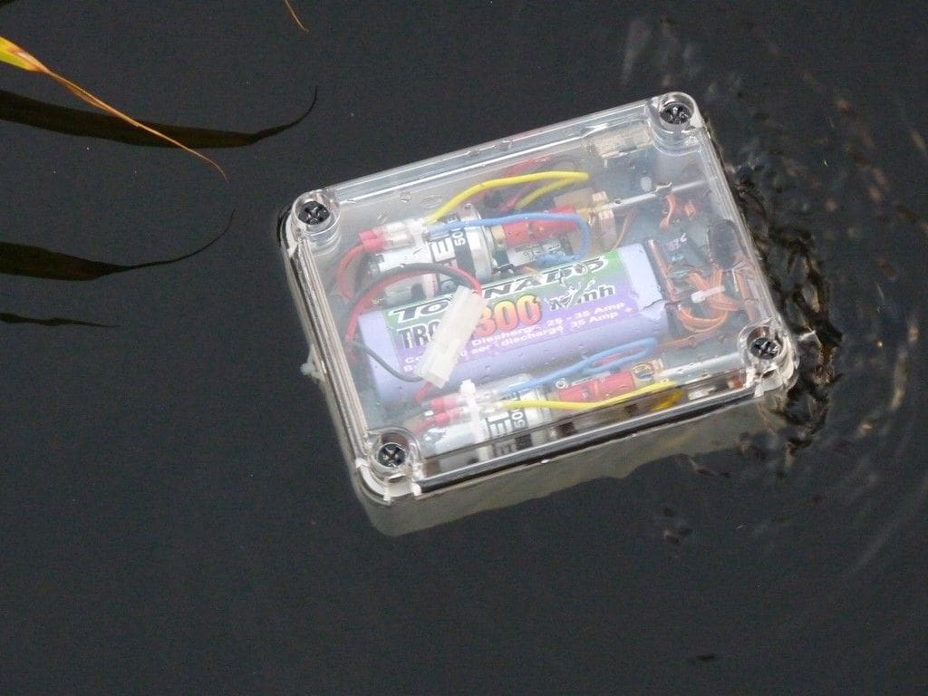
The completed power unit was ballasted with some small pieces of lead flashing tucked under the rear of the propshaft and initial pond trials carried out, Photo 6. Not surprisingly perhaps, these showed the radio had limited range and it would be necessary to bring the receiver aerial out of the box and up inside Nessie’s neck. During later development of the model, a small hole was drilled in the power unit to allow the aerial to exit the box on the right hand side. This was sealed, inside and out, with silicone sealant. The aerial is now routed along the right hand side of the enclosure and retained by self adhesive cable clips. The remaining section of the aerial is then fed up the tube in Nessie’s torso just prior to sailing.
Overall the system worked well, although directional stability was poor and it was obvious that Nessie would need a keel to minimise her tendency to snake from side to side when trying to steer in a straight line. However, since she is to all intents and purposes a snake, a bit of snaking is no bad thing! After about 20 minutes wandering around the pond on its first trial, the power unit was recovered and the lid removed to reveal a dry interior, so all seemed well with the propulsion system and it was time to move on to Nessie’s body.
Head, body and tail
The Ron Rees’ article in the July Model Boats magazine suggested various possible types of foam which could be easily carved or sanded to shape. A trip to our local Travis Perkins builder’s merchants came up with the suggestion to use Celotex. This is a foam insulation board, available in various thicknesses and we came away with a 1200mm by 450mm sheet, 50mm thick after parting with about £7. Bigger and thicker sheets are available, but this size is convenient to handle and would be big enough to make Nessie, The sheet is covered on both sides with a thin layer of aluminium foil, but this can be peeled off quite easily to leave a smooth, carvable and sandable foam surface.
The next step was to roughly mark out the head and neck of Nessie on a cardboard template and then cut out two pieces so that they could be laminated together to make a 100mm thick section. The first component was laminated using waterproof PVA adhesive which worked, but was not a totally satisfactory glue for bonding the two pieces together. The fact that our sheet of Celotex was slightly bowed did not help either and we had to use a heavy weight to hold the two pieces flat together while the glue dried. So, first lesson: Make sure your sheet of Celotex is flat! A second sheet we bought later for another project was much better and easier to work with.
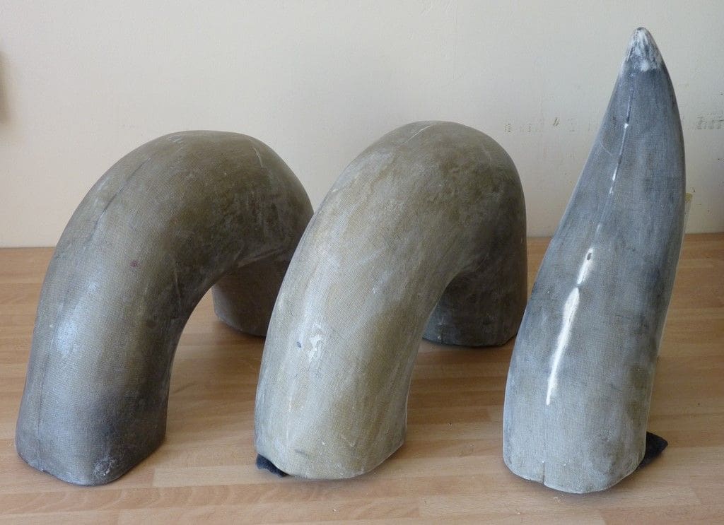
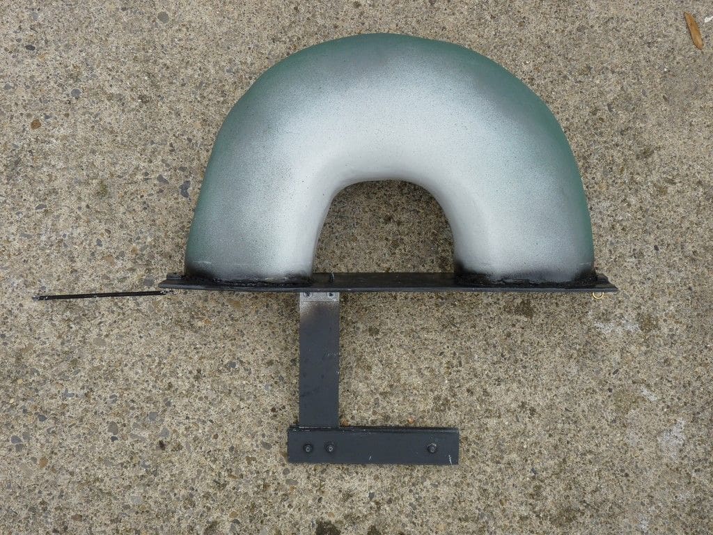
Our daughter Katherine had volunteered to be the sculptor and we went off to Kirklees MBC Gala day early in July, leaving her with the slab of foam, several sharp kitchen knives and instructions to be careful (i.e. not to cut herself!). We had expected the first attempt to be a bit of an experiment, probably to be followed by a second carving session on another block of foam. However on our return, there was a very lifelike head and neck, about 350mm high, and a big pile of foam shavings. After this encouraging start the two humps and tail section were made in the same way. Each of the humps is about 350mm long and 200mm high. Having learned from the experience of using PVA adhesive on the head, we changed to a cartridge of Evo-Stik ‘sticks like ****’ all weather adhesive, but this was not much better than the PVA as it turned out.
Elizabeth then took over from Katherine and sanded down each of the body parts to a final smooth finish, filling where necessary around the mouth, eyes and eyebrows, Photo 7. Each section was covered with the leg of an old pair of tights and given several coats of Eze-Coat water based resin until the mesh of the covering had been filled. The covering method has been very effective giving a tough waterproof coating that seems to resist bumps and knocks well.
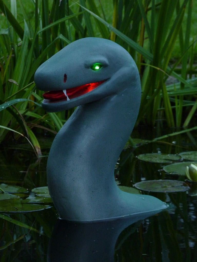
After finally sanding smooth, each section was given several coats of Halfords acrylic grey primer, followed by an overall coat in a lighter shade of grey that we happened to have in stock, Photo 8. The upper surfaces were then given several coats of dark green with lighter green patches applied afterwards with an airbrush. All the painted areas were allowed to blend into each other giving a very realistic camouflaged look representative of a real aquatic animal.
Power unit box and keels
Elizabeth made the box to hold the power unit from 3mm ply. The rear wall has two 45mm diameter holes to allow the power unit to be fed into the compartment at an angle from the top and then sit snugly inside with the propellers protruding from the back. The corners of the compartment are reinforced with strips of pine, about 8mm square, Photo 9. The whole box was eventually given a couple a coats of Eze-Coat resin to protect it and coat of matt black primer to camouflage the underwater sections.
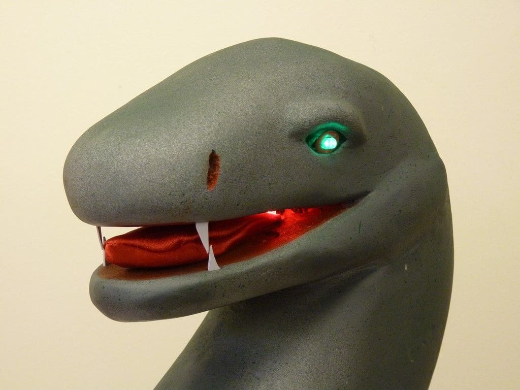
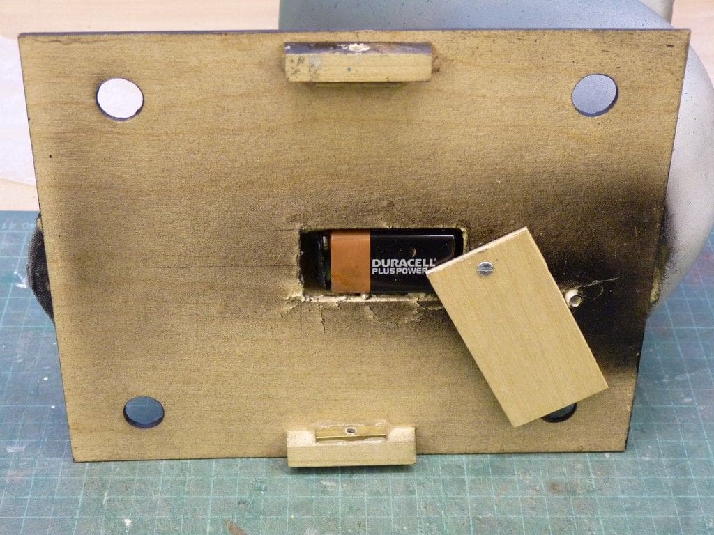
We had decided that Nessie would have a green LED in each eye and a red one inside her mouth. These are powered from a 9v battery fitted in a compartment at the bottom of the neck, Photo 10. This works well and the fact that the battery and connections are underwater does not affect the operation of the LED’s. However since the water in our pond at Goole is slightly salty, it is necessary to remove the battery and rinse and dry the connections after use, something I am not very good at remembering to do.
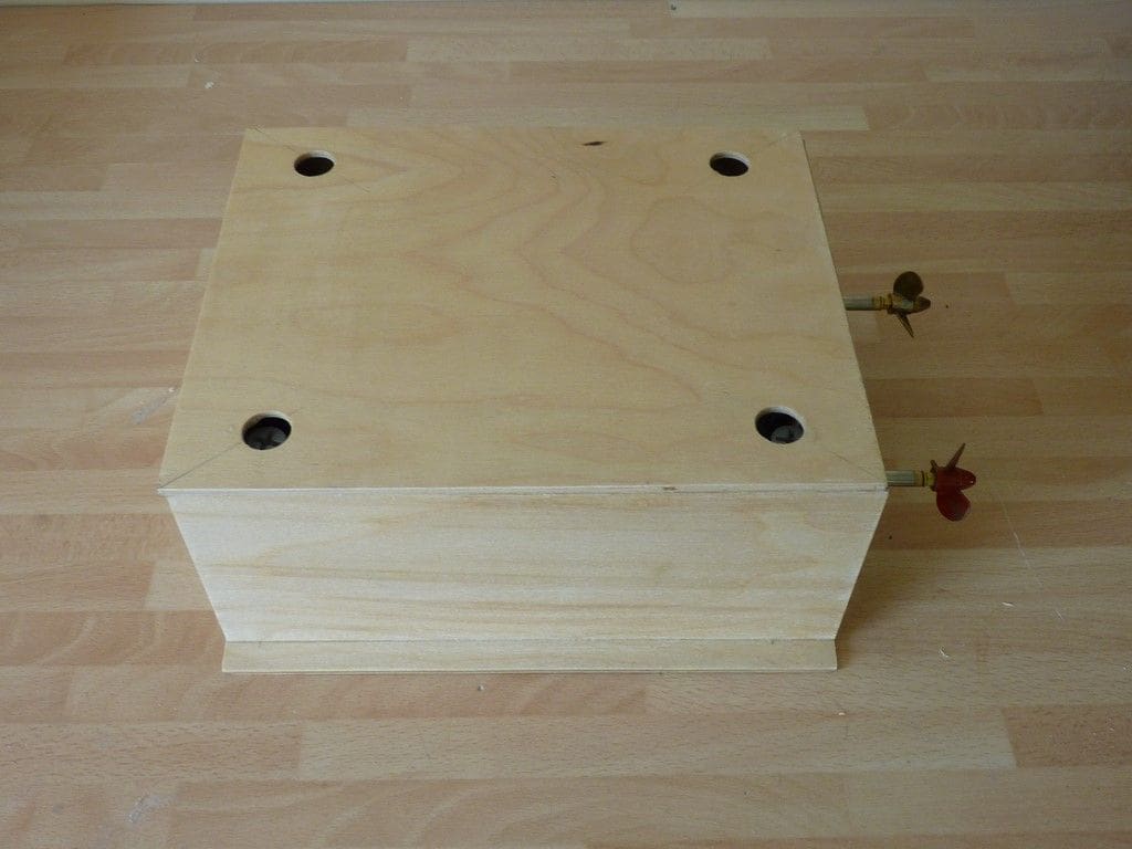
It was easy to drill a hole up through the foam from the base to the back of the mouth using a length of brass tube mounted in the chuck of an electric drill. A cross-drilling from each eye socket into the mouth allowed all the wires to be inserted. It was a bit of a fiddly process, but some stiff wire was used to pull through a length of fishing line and then this was tied to the LED wiring and they were all pulled into place. The tongue was made from a piece of red satin and the fangs from small pieces of white styrene sheet glued into slits in the foam of the head. A second hole was drilled up inside the neck and head from the base and a length of plastic tube inserted and glued into place. This is to allow the receiver aerial to be fed up inside Nessie’s torso prior to sailing which was glued to the lid of this box and at this point we finally found an effective adhesive for the foam. Gorilla Glue is a foaming adhesive activated by water and it worked really well to fix each of the foam body parts to their respective ply base. A hole was previously cut in each corner of the box lid to allow any air trapped inside to escape, Photo 11. The lid is fixed to the sides of the box by a single screw through each side which engages a captive nut on the lid.
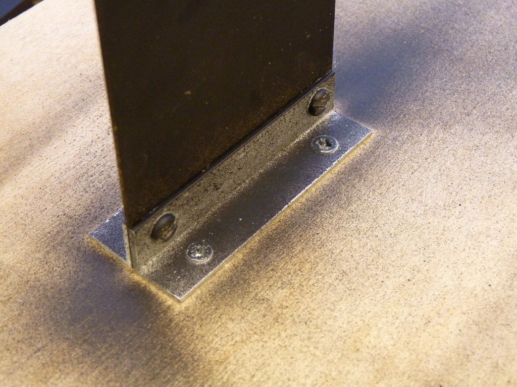
The keel on the power unit box was made from brass plate (in fact, part of a door fingerplate from B & Q). It was attached to the base of the box using two pieces of aluminium angle which are fixed onto the underside of the box using short countersunk screws, Photo 12. The keel weight is made from lead flashing strips, and trial and error testing was carried out with them clamped to the keel until we had the right weight and position. They were then bolted in place with a couple of 6mm stainless steel bolts.
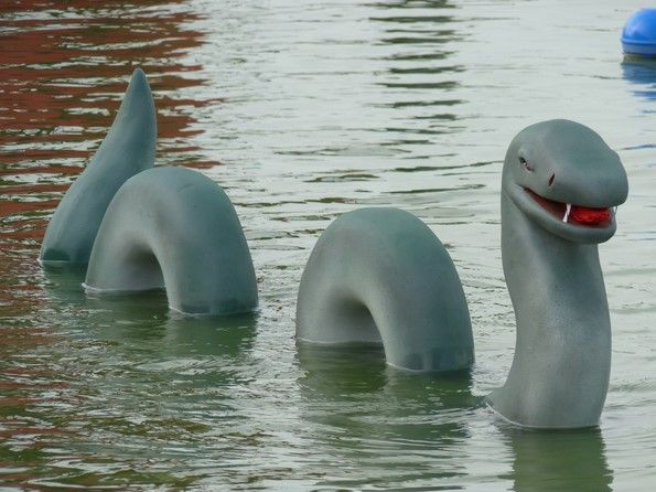
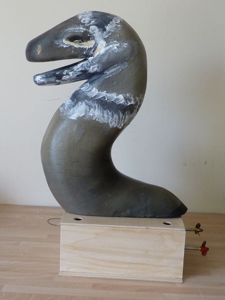
The same principle was used for the other three sections of Nessie’s body. I was uncertain where to position the keel on each piece as I was concerned that the individual sections might wander around as the head towed the two humps and tail. In the end I fixed the keel and weight just aft of centre on the head section, Photo 13. For the two humps the keel was made from a length of aluminium strip with the lead weights attached to form an L-shape under water, Photo 14. The theory was that if the hump yawed to one side the lead weight would act like a rudder and straighten it up. The tail end tends to wag around a little, but overall the effect of Nessie sailing through the water is very realistic, not that I have ever seen the real thing to compare it with!
Each of the sections is joined together with short length of curtain wire engaging in hooks or eyes at the front and back of the sections. This method was chosen for two reasons. First, it gives a bit of stiffness to the connection so that as Nessie slows down, the back does not concertina or overtake the front. The second reason is that it is much less likely to foul the propellers in a tight turn when Nessie winds herself into a spiral.
Sailing Nessie
Preparing Nessie to sail is quite straightforward. The main 7.2v battery is fitted into the power unit and connected, the two speed controllers are switched on and the operation of the system checked from the transmitter. The lid of the power unit is then fitted and the four corner screws tightened to pull the lid down on to the O-ring seal. The power unit is then inserted into Nessie’s base and the aerial wire is fed up the tube in Nessie’s torso. If required the 9v battery is also fitted into the base of the torso to light up the eyes. The torso and lid is then attached to the base unit using two screws and each of the sections fixed together with the curtain wire hooks. It takes two people to put Nessie into the pond in one piece, but if necessary this can be done by one person by sequentially connecting each section in the water.
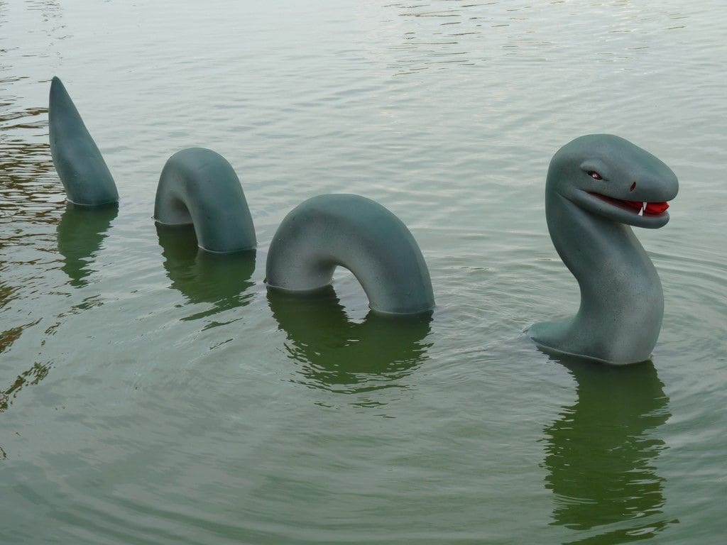
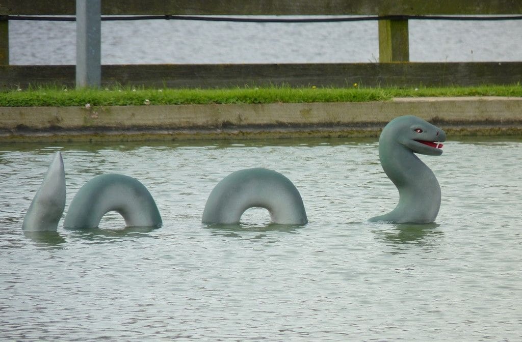
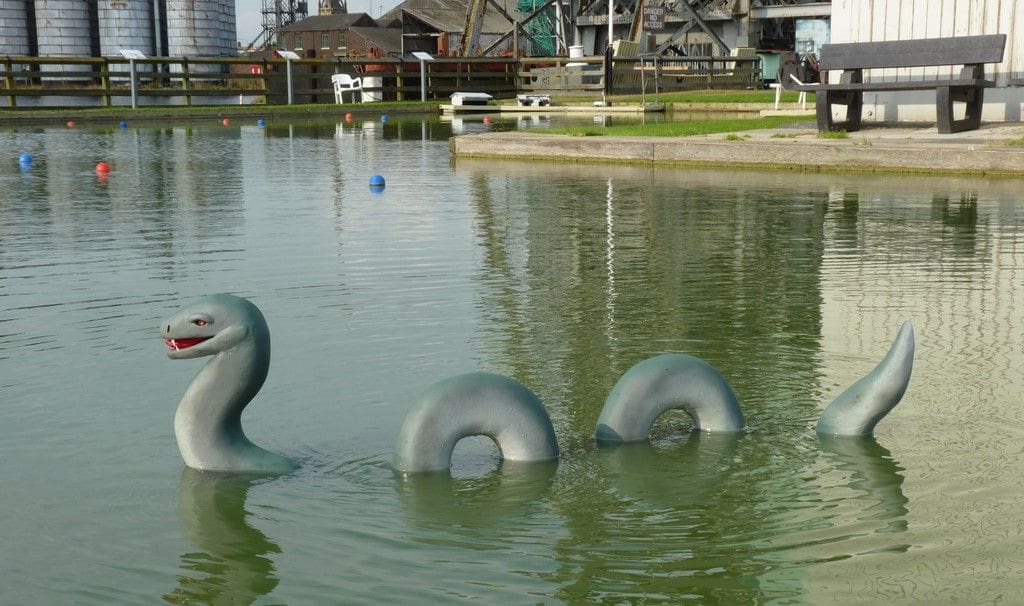
Nessie sails remarkably realistically, Photo 15, and has attracted a lot of attention when sailing at club events or at our local water sports lake. She is very manoeuverable and can turn tightly, but is not very quick and can’t really reverse. The use of a mixer unit and differential propeller thrust for steering works well in this type of model. It is difficult to synchronise the two motors over the whole throttle range, so there is some lead or lag between the motors when accelerating and decelerating. To some degree this effect can be minimised with rudder trim, or by setting the neutral for the two speed controllers to slightly different signal positions. However the slightly wandering behaviour is not out of character and adds to the appeal of the model.
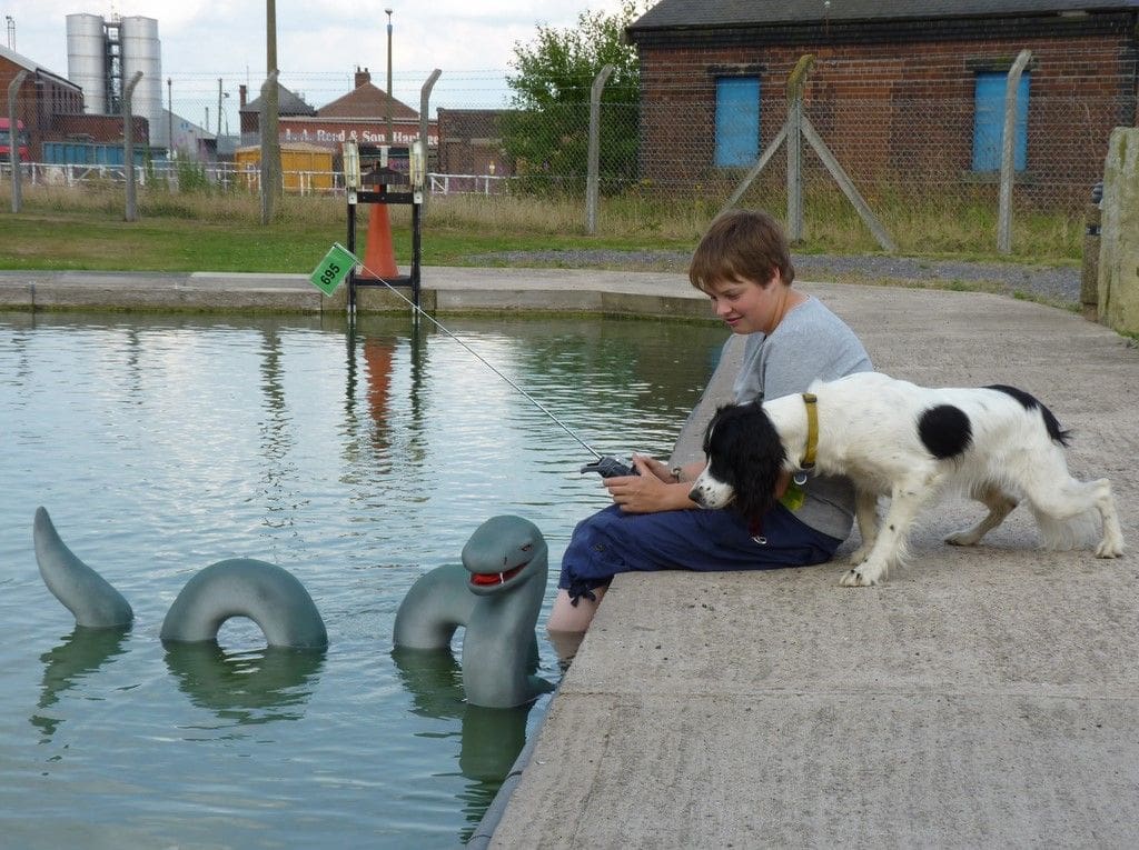
Dogs seem to find her very worrying and usually growl, bark or run away! Onita, one of the trainee hearing dogs that we have socialised, was very wary of Nessie when she was taken along for the maiden voyage, Photo 16!
The idea of a power unit in a self-contained box is quite a versatile concept. The power unit can be used in other models with minimum work and cost. There are lots of potential applications such as a duck, swan, crocodile, turtle, shark, submarine or whatever wacky idea your imagination can come up with.
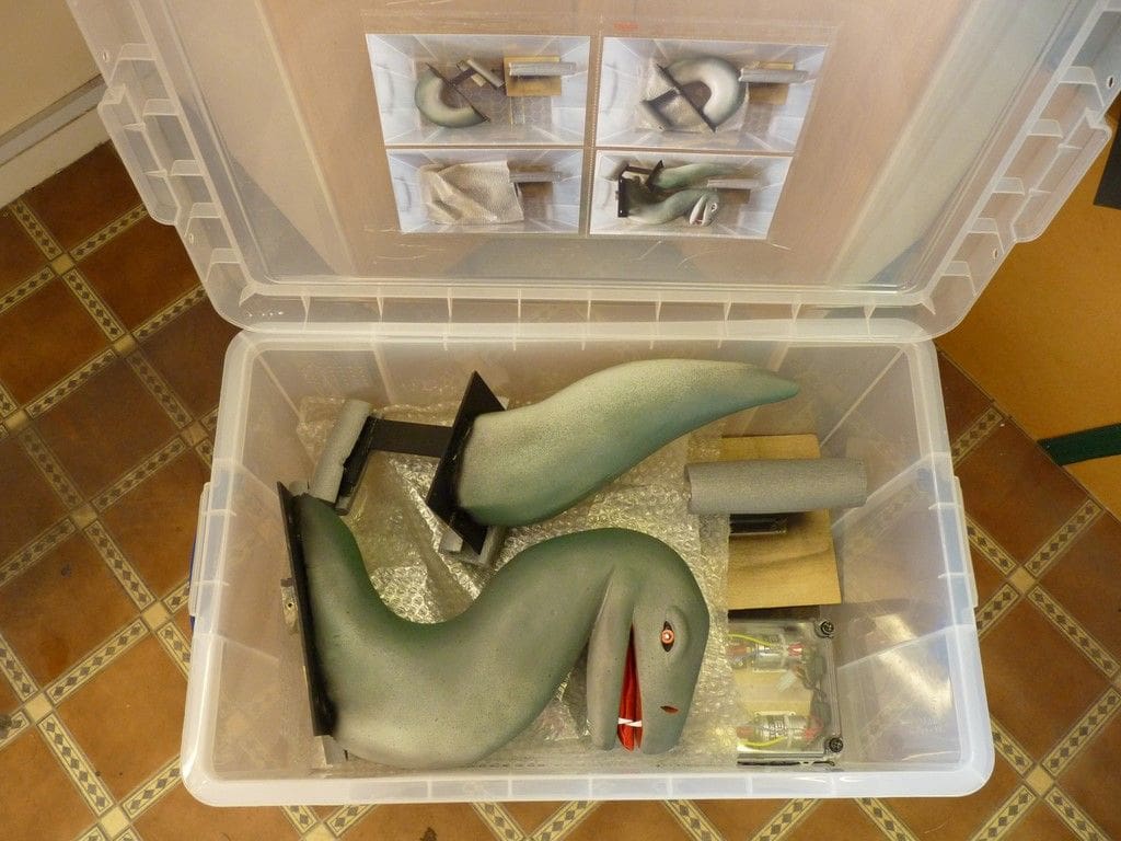
Nessie is an awkward shape to transport and store, so she now has her own box which keeps all the parts together, protected by foam pipe insulation and bubble wrap. Because I find it difficult to remember the right packing sequence, probably a result of old age, we fixed four photos inside the lid for reference, Photo 17.
Overall Nessie has been a very unusual and interesting model that has given us some new challenges. It was an excellent family project with the work split three ways between my wife, daughter and myself. It is probably the fastest build time of any of our models being only four weeks from start to finish and we are really pleased with the end result.
We have still not seen Sean Stewart in his kilt, but he did bring along a set of bagpipes to the Goole MBC Night Sail event, but fortunately he was so keen to take photos of Nessie and the other models he never found time to play them.