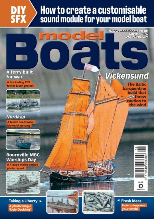
ERIS KENNEDY presents a Feature Plan for a semi-scale destroyer
The first radio controlled model boat I ever built came from a free magazine plan and the design was for a Battle class destroyer prepared by Glynn Guest. That model was called HMS Lagos and the design appealed to me for several reasons. I liked the scale of 1/144 as it made for an economical and portable scale model and it was also sufficiently authentic as well as being relatively quick to build.
Enjoy more Model Boats Magazine reading.
Click here to subscribe & save.
My efforts at construction were not brilliant and I was too financially challenged to invest in a proper speed controller so the model did not cover too many sea miles and slowly but surely succumbed to the ravages of life in the garden shed. I resolved however to build another similar destroyer at a later date and when I finally got round to it some 25 years later, I had developed my skills through building other models. I had also drawn some conclusions of my own as to how best to build a 1/144 scale destroyer of this type. I decided therefore to build an updated version of this model from my own plans.
Given that the plans for the original are no longer available in the MHS list, I went to a little extra trouble and produced this article for those of you who might be partial to building your own Battle class destroyer. I changed some of the constructional techniques and deepened the hull to improve stability. I must reiterate that none of this would have happened if it had not been for Glynn Guest’s original plan.
Having taught myself Computer Aided Design (CAD) I decided to avail myself of some laser cut parts. These were done for me as a ‘special’ by Manzano Laser in the U.S.A., website: www.manzanolaser.com.
MyHobbyStore are now marketing a set of laser cut parts, manufactured in the UK by SLEC, who are perhaps best known for their model aircraft laser cut parts for the RCM&E Free Plans.
Please see pricing and ordering details at end of this article. Alternatively, the plans include sufficient detail to cut your own pieces from1/4 inch and 1/8 inch balsa sheet. Just disregard the locating holes and tabs that exist on some of the parts. Also, you might make use of 1/4 inch square strip balsa rather than cut out the more intricate shapes for some of pieces.
Please note that I have no commercial interest in the laser cutting process, but using such a semi-kit is both an economical and effective way to build a precise and sturdy hull with a minimum of fuss. I think prospective builders may find that the cost is not much more that what it would be to buy and cut the raw balsa alone.
Key particulars
Fully ballasted, the model weighs: 1.134kg.
Length is 800mm (31 inches), beam is 80mm (3 1/8 inches), height is 230 mm (9 inches) to the top of the mast.
So, this makes for a nice size model. If you are scratch building, then it can easily be enlarged, but for me this made up into a nice practical sized model.
Glue
Building in balsa is always pleasant, however the advent of cyanoacrylate glue (superglue) has in my view greatly enhanced the experience. Instead of building a little bit at time, a dedicated session of model construction can be programmed, and much progress can be achieved in a fairly short time. For example the hull can be assembled within an hour from the laser cut parts, so this perhaps better suits the hectic modern lifestyle of some of us. This method of construction is common in the model aircraft industry.
The card veneer over the decks and superstructure is glued in place using a contact cement. I use the smelly type, but the water based ones are probably okay, particularly if you finish and seal the model with a two part sheathing epoxy resin as used to seal wooden surfaces on model aircraft.
Construction
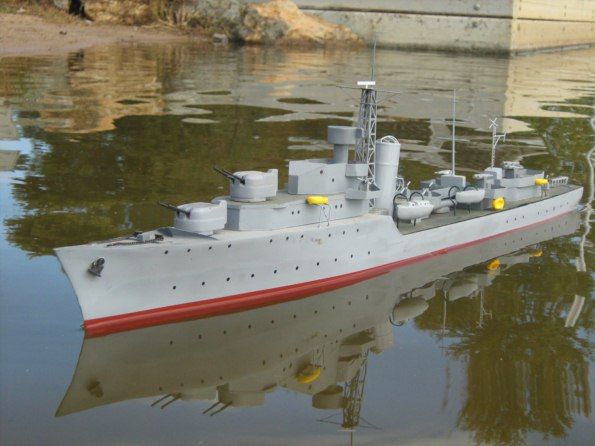
This sort of model is built from the bench upwards.
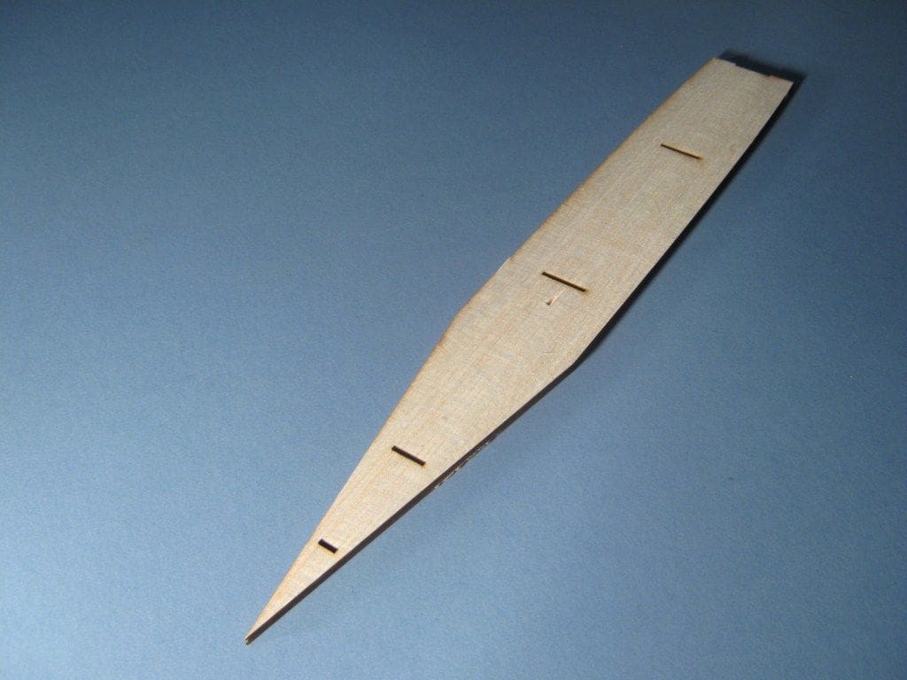
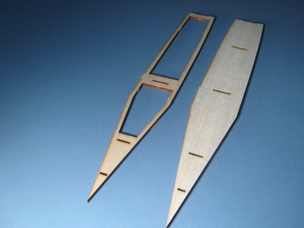
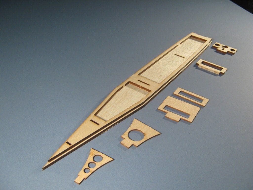
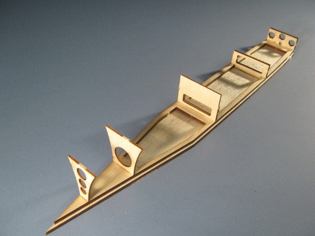
Step one is to cut out the base piece, Photo 1. Next, the inner base goes in place, Photos 2 and 3. If you are not using the laser cut parts you can simply line the edge of the outer base piece with 1/4 inch square balsa strip rather than the complete panel. This last picture (Photo 3) also shows the bulkheads prior to fitting. Note that B3 has a secondary backing piece designated B3A that is designed to support the main deck. Fit B3A to B3 together and glue. If you are using the laser cut bulkheads use the matching lightening holes to line the two parts up correctly. If not, then please refer to the plans.
Prior to installing the bulkheads, please note that the laser cut bulkhead B1 has lightning holes which tend to weaken it excessively. I recommend you reinforce B1 with a doublers of 1/8 inch balsa at this point.
Now go ahead and erect the bulkheads. Make sure you set them square and vertical, Photo 4. It is a good idea to chamfer the edges of the bulkheads forward and aft to match the curvature of the hull in those areas so as to create a good jointing surface for the side skins.
Fitting the hull sides and pulling them together is the only slightly awkward bit in the whole model. Start by sitting one hull side (either port or starboard) in place on the step created around the flat bottom by the hull base inner piece. Adjust so that it is square and properly seated and pin in place. Obviously, the rear section of each side is free and extends past the rear of the flat bottom. Do likewise with the other side so they both match perfectly. Once happy, loosen the sides on the pins slightly, inject thick superglue into the joints and push together quickly and firmly. You could use PVA or epoxy glue, but superglue (Zap-A-Gap in this case) certainly speeds construction. Photo 5 has both sides pulled in against the aft bulkheads (where the hull sides are parallel) and glued in place.
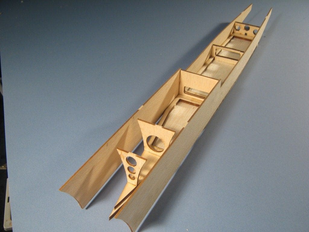
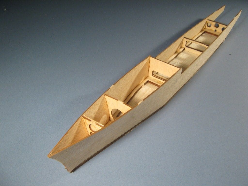
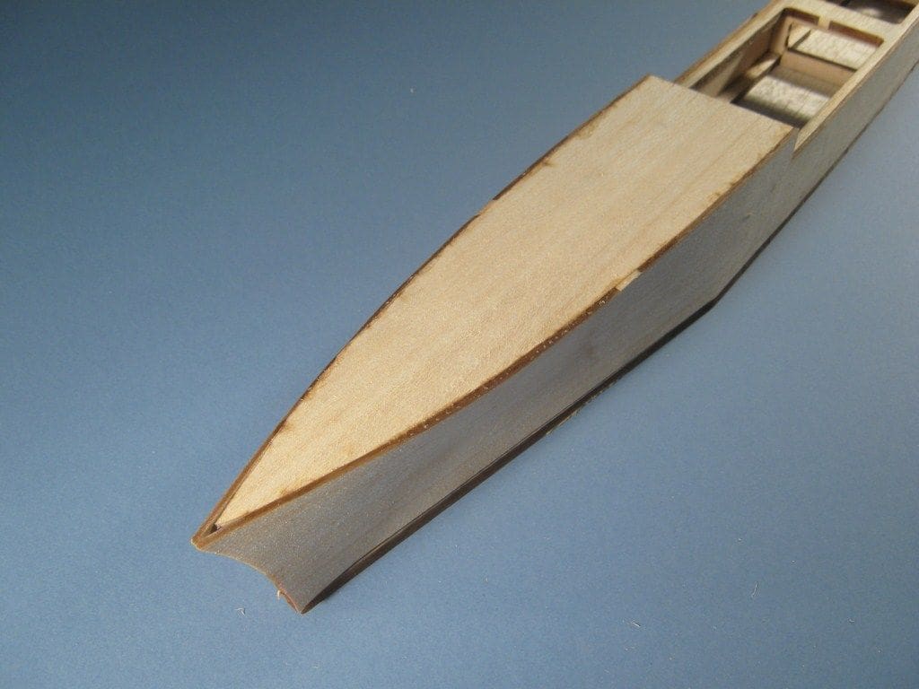
Now for the tricky but satisfying bit. Working from amidships, simultaneously and progressively pull the sides in together and glue them against the hull base and bulkheads working towards the bows. The objective of this is to establish a flare in the bow as you work forward. You can do this task easily by hand, cementing with superglue as you move forward. Keep working at it until you get to the stem. At this point you will now have a pointy box with some flare at the bow end, Photo 6.
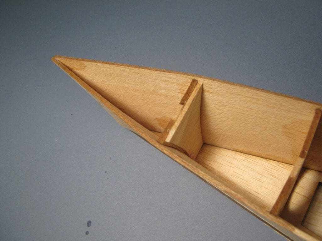
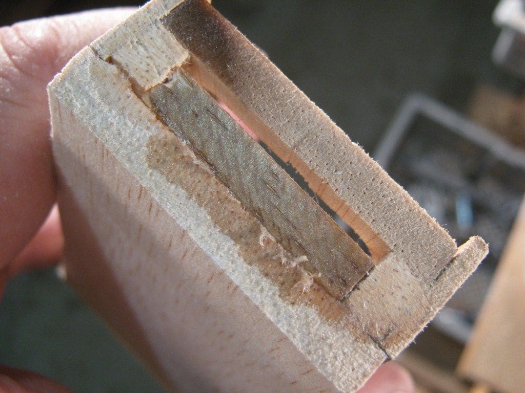
It is advisable to reinforce inside the bow joint with a little 3/4oz fibreglass cloth set into place with some superglue or epoxy. This is not critical but is advisable and Photo 7 is a close-up of the bow section interior.
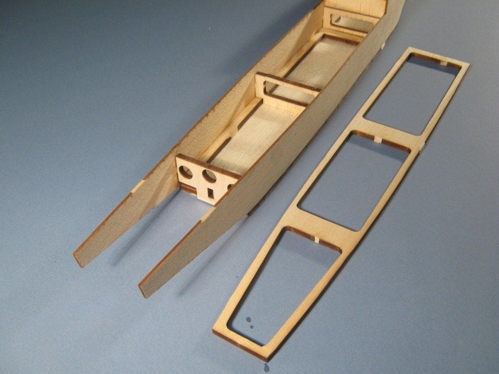
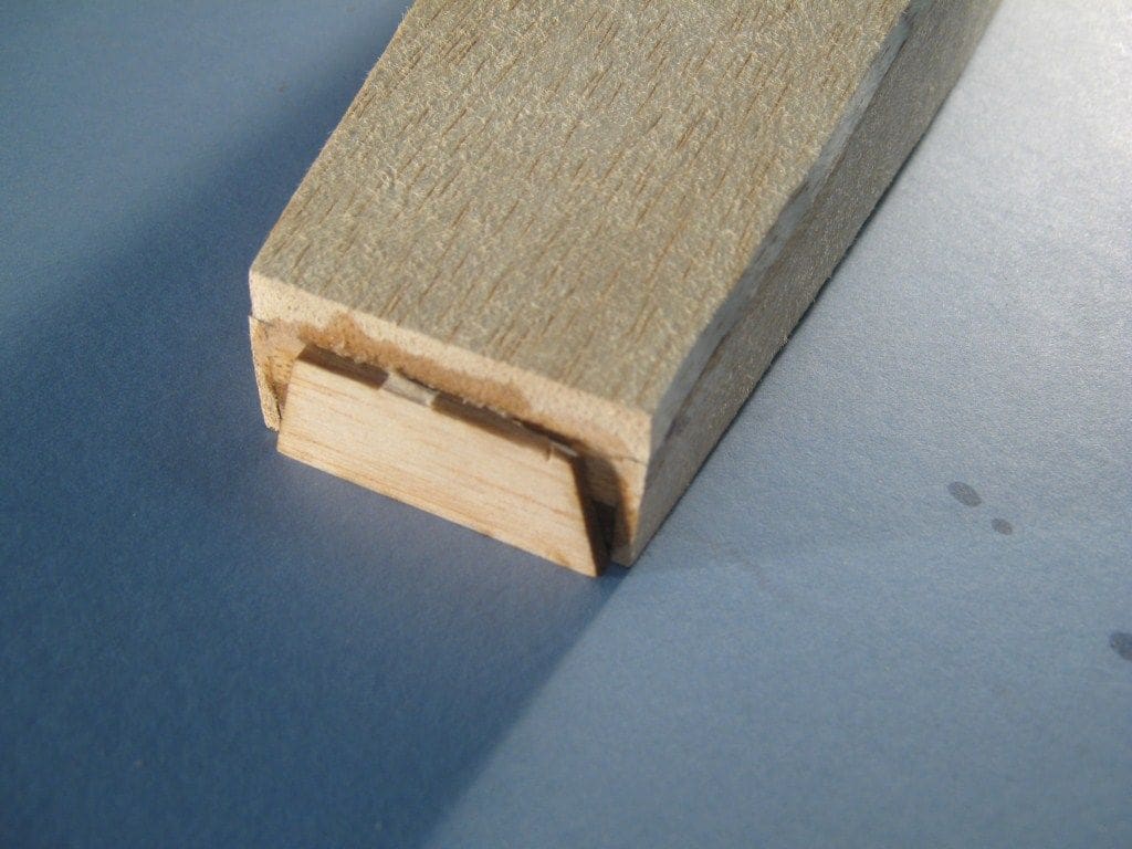
Once the sides are secure the main deck support piece, which fits behind the break of the forecastle, can be fitted, Photos 8 and 9. This fits on top of the bulkheads and the sides at the stern are pulled inwards and glued to it. You will note that this piece is 1/4 inch down from the top edge, thus leaving a convenient ledge on to which the main deck will eventually fit. If not using the laser cut parts, this ledge could be created by just gluing 1/4 inch square balsa strip around the hull sides 1/4 inch below their top edges.
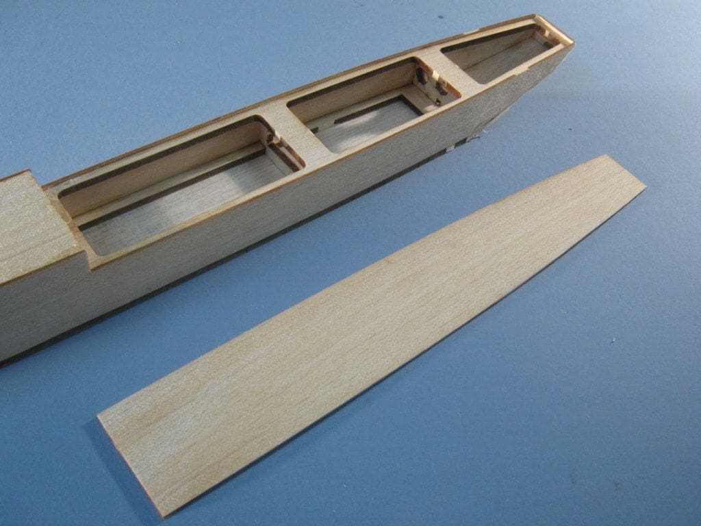
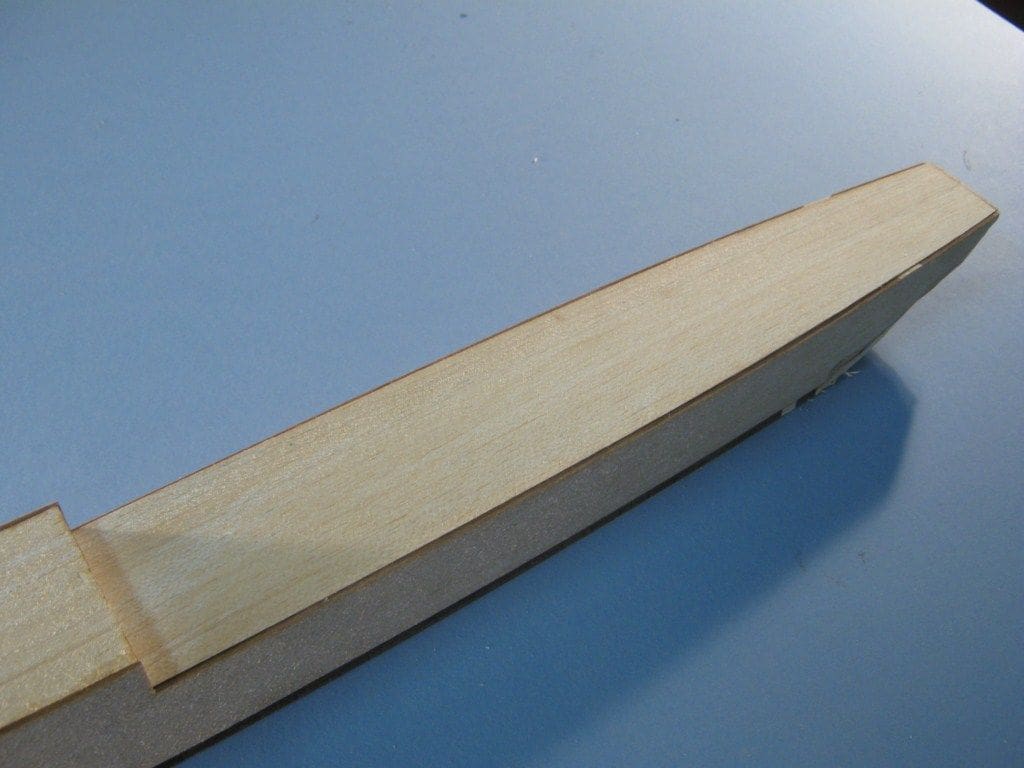
Fore deck
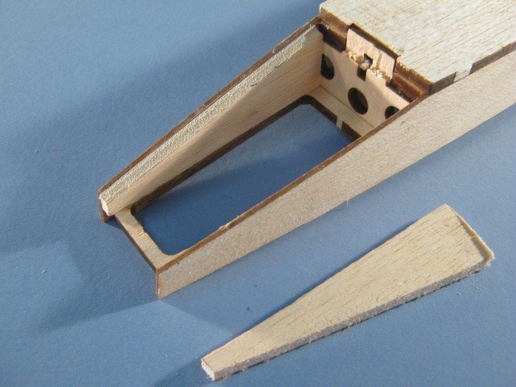
Returning to the forward part of the hull and it is now time to install the fore deck, Photo 10. There is no sub-deck frame for this as it is not removable and it will just need a little chamfering to obtain a snug fit over the bulkheads and inside the side pieces, Photo 11. Alternatively, if not using the laser cut parts, you could use the inverted hull as a template to cut out a fore deck to fit. Since it fits inside the hull rather than on top of it, all you would need to do is to take off an 1/8 inch strip around the marked edge so the part hopefully snuggly fits into the top of the hull nicely. Once a good fit is obtained, it may be glued in place with either thick superglue, PVA or epoxy. As I wrote earlier, this part of the decking is not removable. It is therefore essential to ensure that all the internal joints of the hull sides and bottom are sound. Therefore a fillet of epoxy glue or fibreglass resin inside will do no harm. The bulkheads are not all solid, so there is ventilation should any water get inside and with deft fingers and brush, applying the strengthening fillet to the inside of the joints is not that difficult. As with Glynn Guest’s models and his recommendations, it is best to leave the inside unpainted so the wood can breath.
Underside aft
Now, please invert the hull and turn your attention to the aft section. The plans vary slightly from the what is shown in Photo 12. If you have the laser parts or have cut out the hull sides from the plans there will be a 1/4 inch step in the side pieces commencing at the point where the hull bottom turns up towards the stern. The idea being to pull the hull sides into the transom to create the stern shaped section
I decided to err on the side of strength and insert extra strips of balsa so that the sides were built up as solid, both port and starboard, later to be carved and sanded to a nice shape. This was achieved by first installing the stern base piece between the hull sides and gluing it in place. Next, the hull doublers were fitted inside and glued (two doublers of 1/4 inch balsa each side are more than adequate). Photo 13 is looking directly at the stern now, but without the transom piece fitted. This was then glued to the rear of the hull, Photo 14, and was used as the former to which the now solid port and starboard sides could be sanded to the correct final shape. To some extent this all depends on which way the grain of the balsa runs. If it is vertical then there is no problem with bending it along the curve of the deck edge, but if it is along the run of the hull sides, then although it can be ‘pulled in’ at the bows quite easily, this is not so practical at the stern.
Main deck
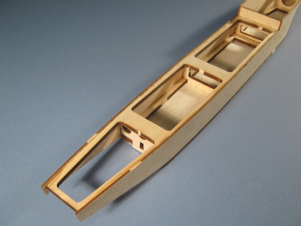
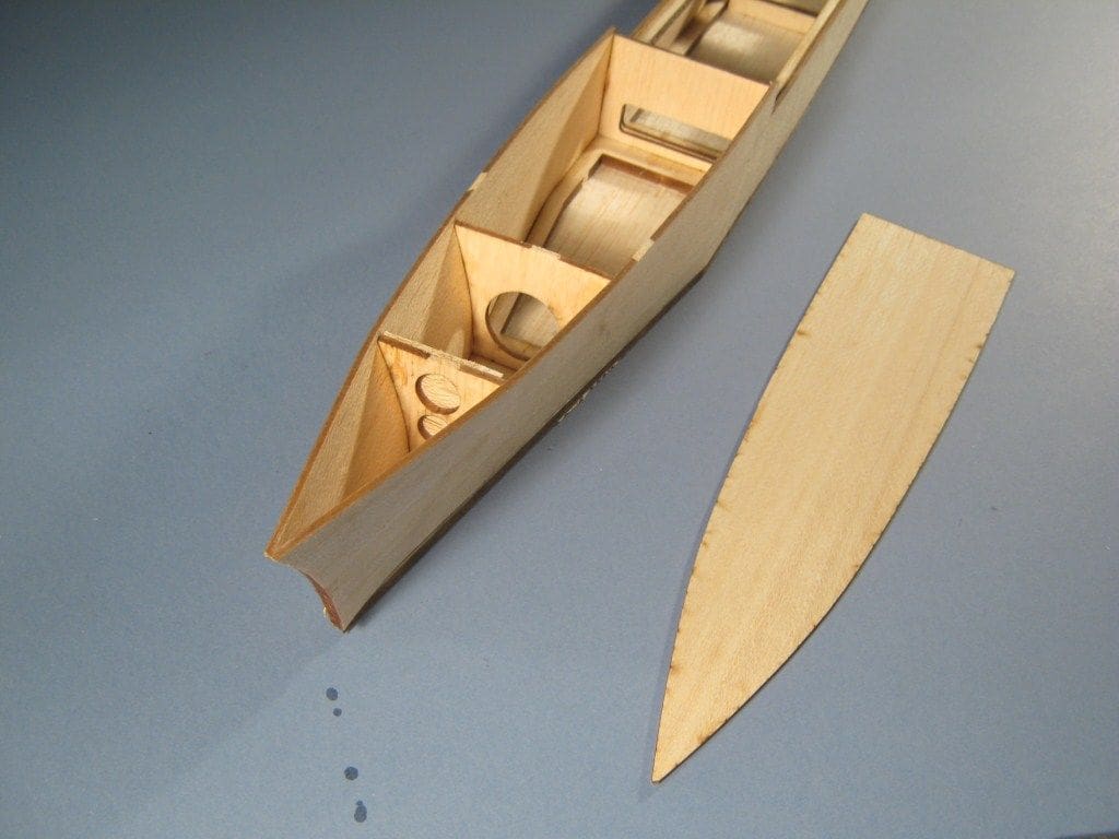
The final part of hull construction phase is to fit the main deck. It is NOT glued in place and is removable as a complete unit, again in the style of many of Glynn’s models. The laser cut deck should fit (just drop!) into place with minimal sanding or trimming, Photo 15, but if you are building from scratch without the laser cut parts, then again use the inverted hull as a template to mark out the deck edge line on a suitable piece of balsa. Please note then that the exterior dimensions will need to be reduced by the thickness of the hull sides. Photo 16 is of the main deck now slid into position.
On the model constructed from laser cut parts, the deck is further located by balsa blanks glued to the underside of it which fit in the large access holes in the sub-deck support. To fit these, fill the hull with scrunched up paper such that this paper supports the blanks. Apply glue to the blanks and then press the deck down in place onto them and leave to dry. When the deck is later removed after a judicious interval it should have the blanks attached to the underside of the deck in the correct place. It may be that some of the paper has adhered to the balsa wood – this is no problem as it can be easily sanded away. Photo 17 shows these deck locating blanks in place. I had later to do a little surgical trimming to accommodate some of the in internal equipment. This photo is also a good clue to the fact that I built two of these models!
Shaping the hull
This is a most pleasant part of hull construction, however be careful and do not over do it. A sharp knife used with caution and sandpaper wrapped around a block will speedily achieve a nice smooth destroyer like shape and finish. Use fine rather than coarse sandpaper as you can always sand a bit more, but it is hard to put wood back once it has been turned to dust, particularly balsa. It might be worth (as Glynn does) adding a hardwood strip to the point of the bow as this is the most likely part of the model to collide with something. If you do over reach yourself when sanding, scrap balsa can be glued into the defective area and then sanded again once all is dry.
Cue the card!
This sort of model boat building benefits from the use of thin glossy card of the type used in birthday cards and brochure holders. It can be applied using contact adhesive and is useful for decks and superstructure where we want to cover the relatively soft balsa and also for creating a simulated steel deck.
The original Glynn Guest HMS Lagos, which inspired HMS Embling, had strips of card glued lengthways along the hull to give the impression of a welded steel hull. This has not been done on HMS Embling, but the fore deck was laminated with a single piece of card along with the main deck.
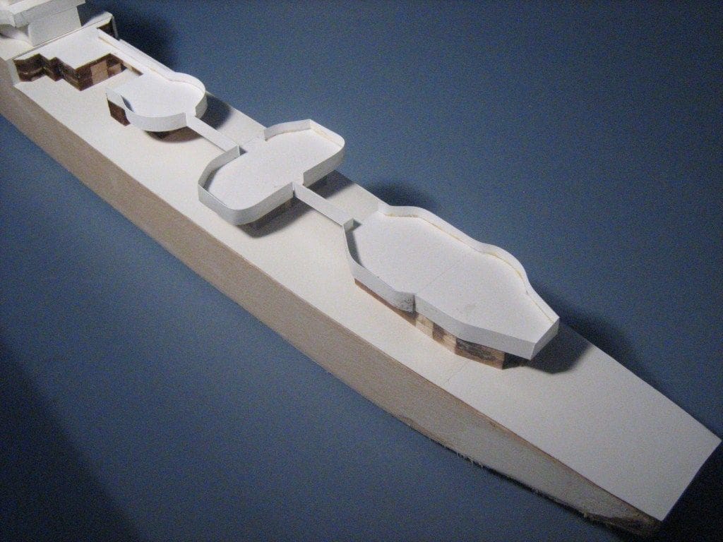
The easy way to do this, is to lay an overly wide piece of card over the fore deck and main deck (inserted into the hull). Invert the hull onto a flat surface and trim the card flush with the hull sides using a sharp knife, being careful not to cut into the hull. This should mean that not only do the balsa decks sit within the hull (the main deck is removable), but the overlay will then fit over the hull sides, thus hopefully creating another barrier to water ingress. Photo 18 shows the deck card overlay in place as well as the use of card to make up lightweight superstructure gun platforms etc.
These card surfaces can be made more durable and resilient by coating them with thinned two part epoxy resin (as used on model aircraft wooden surfaces). Using 30% methylated spirits as a thinning agent after you have mixed up the epoxy will ensure it soaks well into the card.
Superstructure and fittings
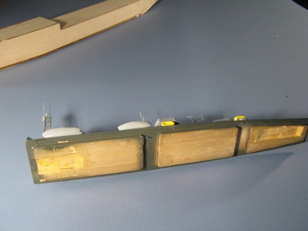
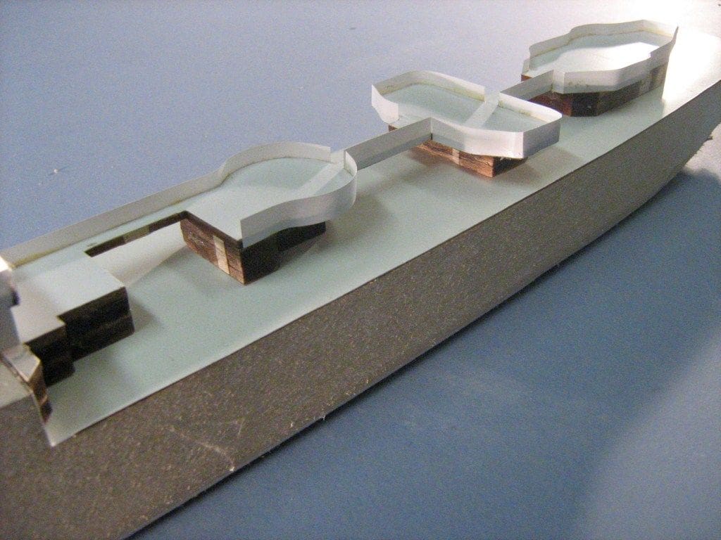
The superstructure is comprised of built up blocks made from balsa which are then laminated in card. Many of these components were cut out as blanks by laser, but if you are scratch building, a sharp knife and a good fine saw will do the job just as well. Do not use anything other than balsa and card for the superstructure or top weight will be increased unnecessarily and possibly effect the model’s stability. Photo 19 is of the main deck superstructure blocks with card used for their gun platforms. The balsa appears to be dark brown and this is because of the laser cutting process which ‘burns’ the edges slightly.
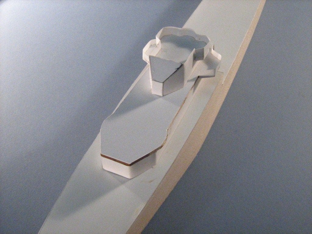
Photo 20 is of the bridge and B turret platform. Again, the former is from balsa sections which are then veneered with card.
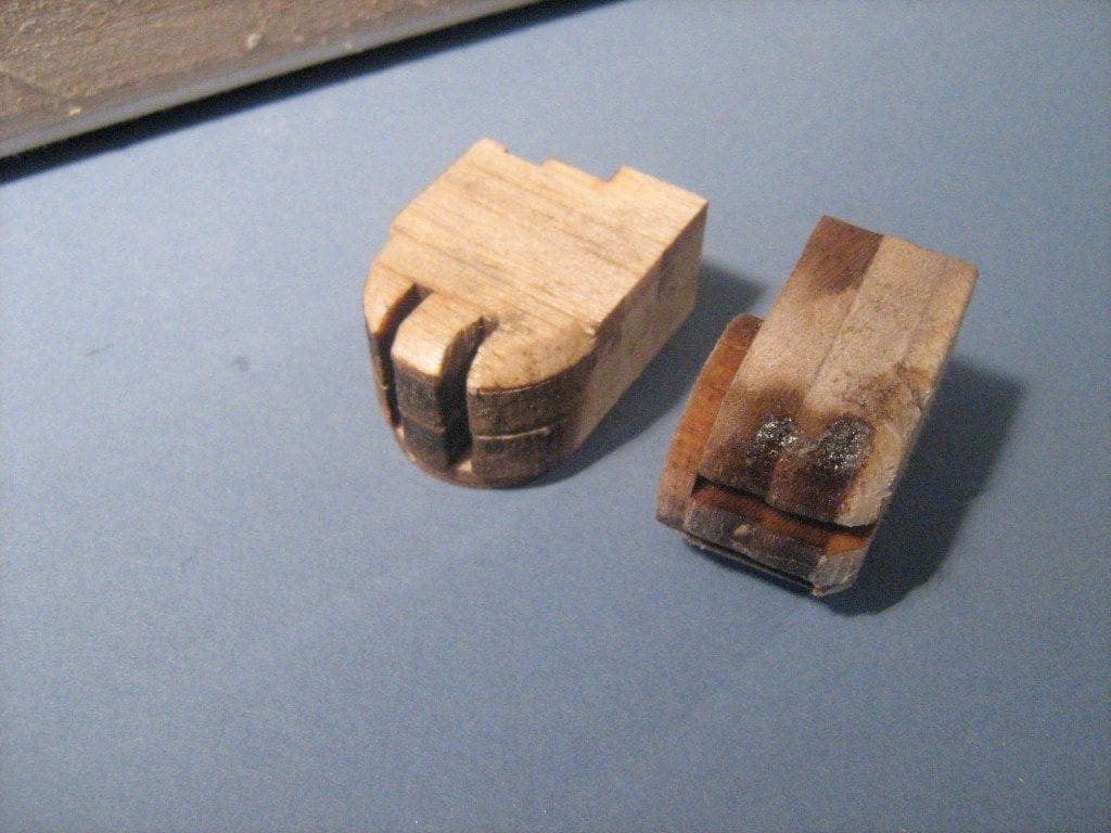
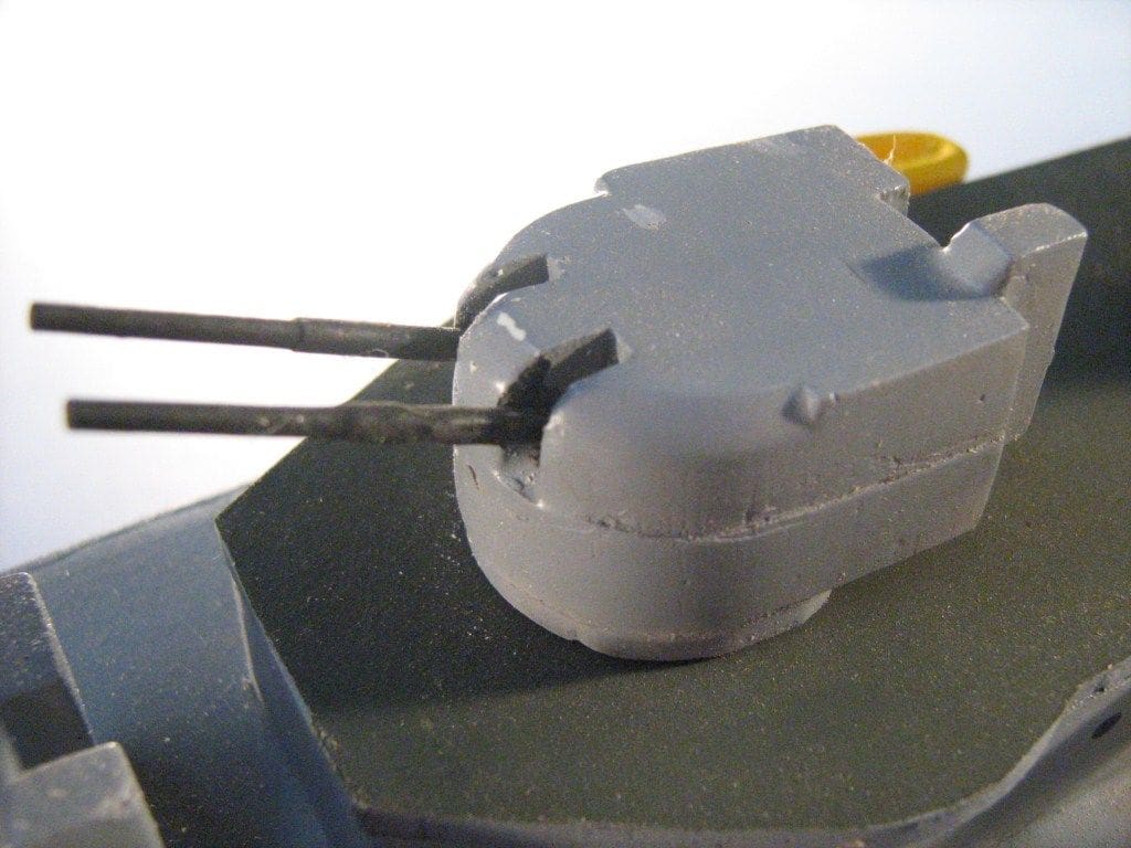
The turrets for the main armament are shaped balsa blocks, Photo 21, with the gun barrels of plastic tube, but lightweight brass or aluminium will do the trick just as well. A finishing coat of epoxy resin and then warship grey and they look menacing enough, Photo 22. The ship’s boats are carved from balsa and carried by davits formed from plastic coated steel wire. The bulwarks are all from card strip as mentioned earlier, but an alternative might be very thin styrene sheet.
A real challenge with this type of model is the lattice mast. This can be made with wood, wire and plastic but it is painstaking to make this way. My solution was to draw up the mast in CAD once again and then get it cut from thin card by laser. The result is a flat sheet that can be folded into a three dimensional structure with a minimum of fuss. The kit of laser cut parts should have the mast included, but please double check when ordering. Likewise, the depth charge rack on the quarter deck is also a folded item from laser cut card.
Running gear
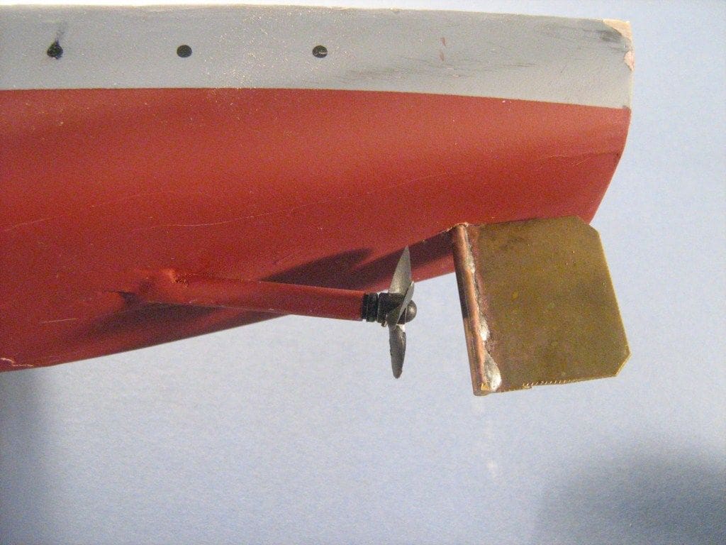
The rudder is a simple home made unit, but if you are not too confident on soldering, there are a number of basic commercial versions on the market. What is particularly important is that the rudder post is set vertical, both fore and aft and port to starboard, Photo 23. Ideally, the rudder blade should not extend past the extremity of the transom. However, and it is a ‘big however’, please ensure that the rudder blade and its shaft can be unshipped from the model so that the propshaft can be easily withdrawn.
The propshaft and tube is any conveniently available commercial product. A lightweight type is perfectly adequate for this model. Ideally, the rear of the propeller boss should be about 1/4 inch in front of the forward edge of the rudder blade. The propeller should be able to rotate with adequate, but not excessive, clearance to the hull. Having the propshaft as close to the hull bottom as possible, in my experience helps avoid excessive hull rolling.
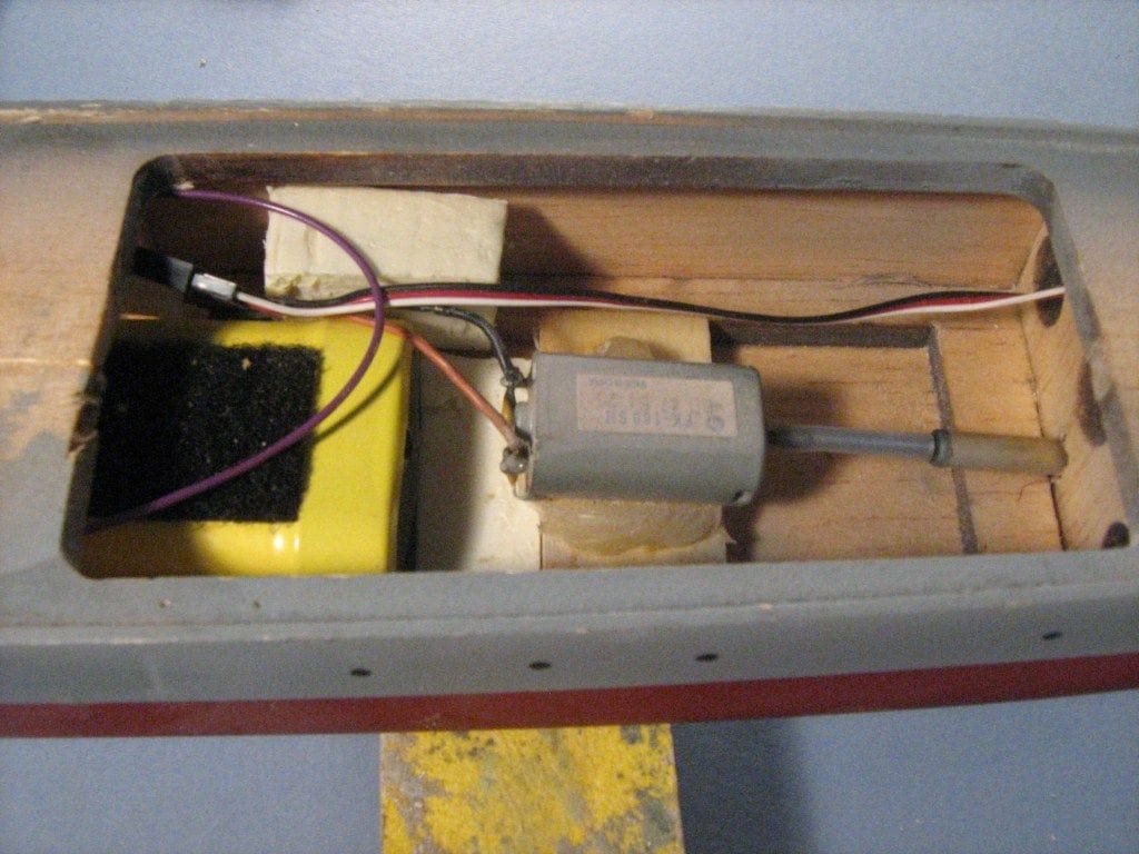
The motor I used is a small and old 180 type, Photo 24. Actually any current 280 or 380 type low current drain electric motor will also do, but just choose something small since the model is lightweight and does not need to be overpowered. In Europe, motors if they have the CE sticker should already be suppressed. If it is not, then there is a fair chance the motor will interfere with the receiver. Suitable suppressor packs are readily available at low cost and these should be fitted to the motor.
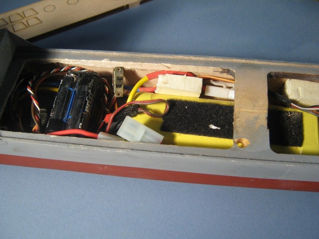
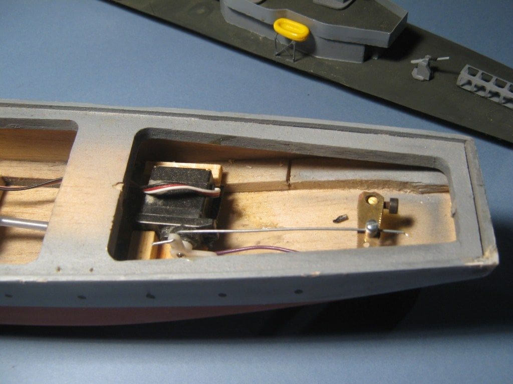
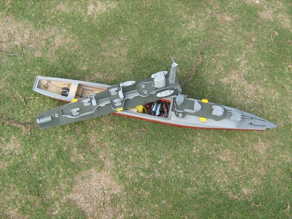
For motor speed control there are various units that will do the job, many of which are advertised in this magazine. A 15 amp electronic speed controller will be more than adequate, but a smaller version will be fine with this type of low power motor. I used an older non-BEC (Battery Eliminator Circuit) type, so had to install a separate receiver power pack for the r/c gear. The drive motor is powered by a standard 7.2 volt ‘buggy pack’. This is all a bit of a squeeze, but it does fit, Photo 25. Photo 26 is of the rudder linkage arrangement – there is nothing unusual about that except that a standard size servo will have to be fitted on its side. Having a one piece main deck does enable easy access and Photo 27 is an overhead view of the model.
Finishing
Over the years I have used different finishing methods on the models I have built. What have I learnt? Well I think the best finish and the most durable comes from using the two part epoxy coating resin of the type used for sealing wooden surfaces on model aircraft. It is light, tough, sandable and waterproof. In particular, it seems to sand very well if thinned with 30% methylated spirits which also increases the penetration of the epoxy into the balsa wood.
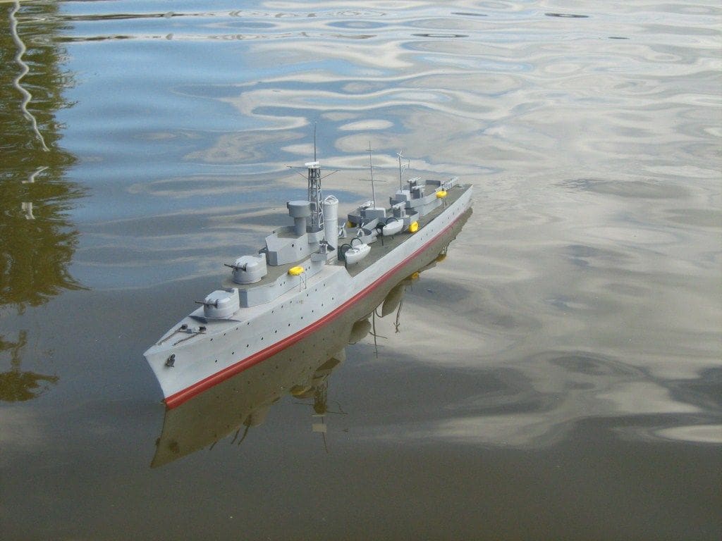
The final colour coats are your choice – airbrushing is handy when endeavouring to obtain a nice even finish and aerosol cans are even easier. The colours used here were home mixed and conform to the ‘looks right’ principle rather than being the absolutely correct colour scheme. I don’t think the real vessel had a green deck, but the contrast makes for a more interesting looking model.
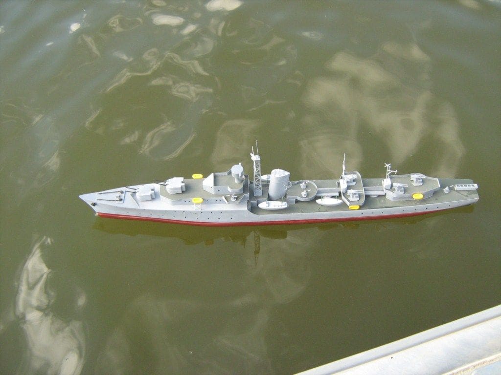
On the Water
This sort of model is fun and quick to build, but they are at their best on water. Despite the relatively small power plant, HMS Embling slips along at a good speed on about one third throttle.
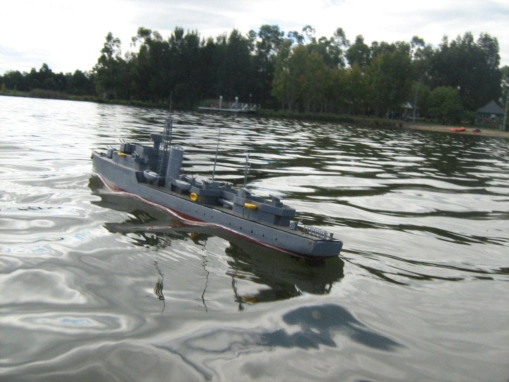
Some expect that a model boat should handle like a motor car, but this is not generally true. Water is a mobile fluid and the wind wants to swing your model around. Stopping when applying reverse thrust is excellent, although the stern swings with the paddle wheel effect as do all single screw models, but you can use this to your advantage when berthing to draw the hull alongside the wharf.
Sea keeping is good, even in relatively boisterous conditions. A little water is shipped at times, however precious little seems to penetrate below decks. Endurance with the 7.2v power pack is at least 30 minutes or more depending on how you drive the model.
Conclusion
This is a simple model, but fun to operate and with scope to increase the detail level if one so wishes. With modern r/c, the weight is no longer a problem with any model and current battery packs have power outputs undreamt of from even just 20 years ago.
Have fun…………!
MyHobbyStore plan and laser cut parts
The plan number is ref: MM2055, price £5.95 + p&p.
MyHobbyStore are also making available a set of laser cut parts, ref: HULMM2055 at a special introductory offer price of £24.99 including free p&p until 28th February 2011 (Please note; regretfully free p&p offer is only for UK mainland customers).
Orders may be placed either online or via the hotline, tel: 08448 488822, Monday to Friday, 9am to 5pm.
Normal price will be £29.99 + p&p from 1st March 2011.