Dr MARCUS ROOKS and his two semi-scale J class destroyers
It can be quite surprising what can turn up at an auto jumble. This was the first one that I had attended for nearly thirty years and Beaulieu is perhaps one of the most well known events in the world of auto jumbles with thousands of punters and hundreds of stalls.
I had gone with a friend to see if I could find any parts for the restoration of my 1960 Honda motorcycles. Very quickly I could see that I would be unlucky, so I turned my attention to other suitable items and I came across two interesting lots on different stalls.
Enjoy more Model Boats Magazine reading in the monthly magazine.
Click here to subscribe & save.
The first was a nicely made old launch which was a little battered, but basically complete. On close examination it held a marvellous example of a permanent magnet motor from about the 1950’s. I didn’t buy it at first but went back later and beat the vendor down to £15. This was of course when I was able to find him again amongst the mass of stalls!
My friend is an avid, dedicated auto jumblist, but I was now ready to go home although it was still only noon. After a picnic lunch it was announced that we should meet again at 5pm. My heart sank, but as he was driving I had little option and off I went again and stumbled upon my next acquisition. A young lad was selling a pair of rather crudely made WW2 destroyer models.
They were without motors, but had a certain amount of charm. Again I did not buy at once but returned and bought the pair for £40 which was not too bad as I thought that I would definitely be able to improve them.
A further hour and a half wait was necessary before we could depart with my purchases. Whilst waiting. I watched the other cars leave and it was amazing what they were carrying and I conjectured that there must be literally thousands of half completed projects across the country.
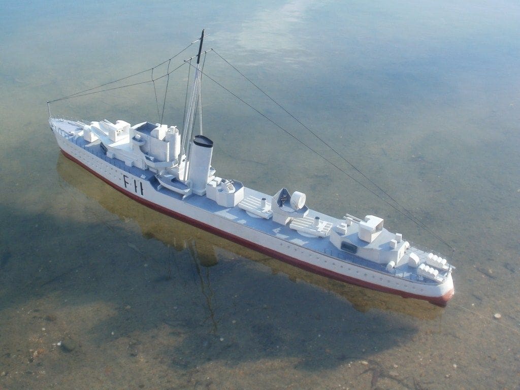
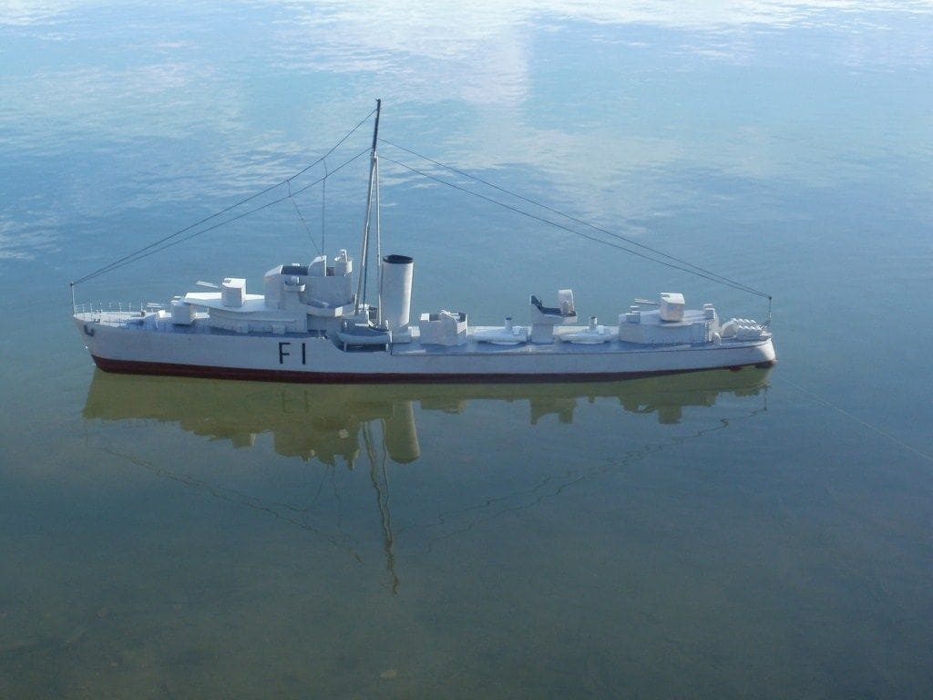
When I eventually got my treasures back to Cambridge, I was able to examine them more closely and I was not disappointed as it so happened. The two destroyers had obviously had been made by the same person to the same basic design. They were single stack boats with three twin turrets. Searching the internet revealed that they were remarkably like the British J Type destroyer, so I decided that I would at least use that design as a starting point for my restoration.
These were handsome ships with three twin turrets, quadruple Pom Poms and other assorted AA defences. They were also fitted with ten torpedo tubes and racks and throwers for depth charges. The J class destroyers were very similar to the K and N classes, totalling 24 launched from 1938 onwards. They were smaller vessels than some others of that period, but had a heavier torpedo armament. Design changes allowed for the fitting of only one funnel and this also reduced the hull length. Their general characteristics were:
Displacement: 2330 tons full load.
Length: 356.5 feet.
Speed: 36 knots.
Armament: 6 x 4.7 inch guns in twin mounts.
4 x 2 pounder Pom Pom quad mounts.
8 x 0.5 inch in quad. mounts.
10 x 21 inch torpedo tubes.
The ships were heavily committed during WW2 and six of the nine J Class vessels were lost
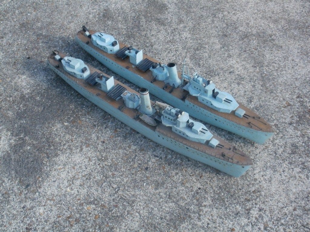
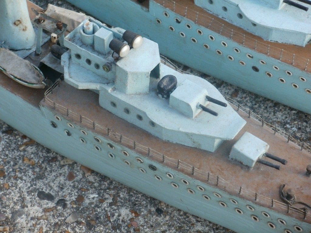
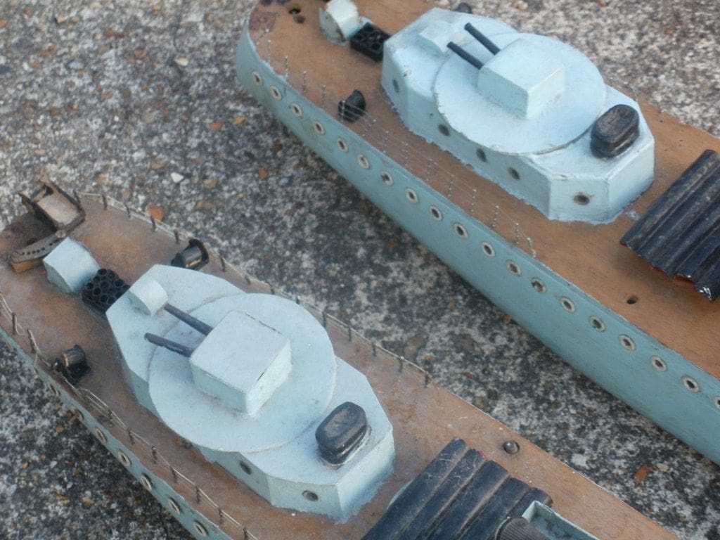
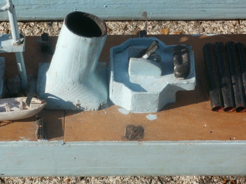
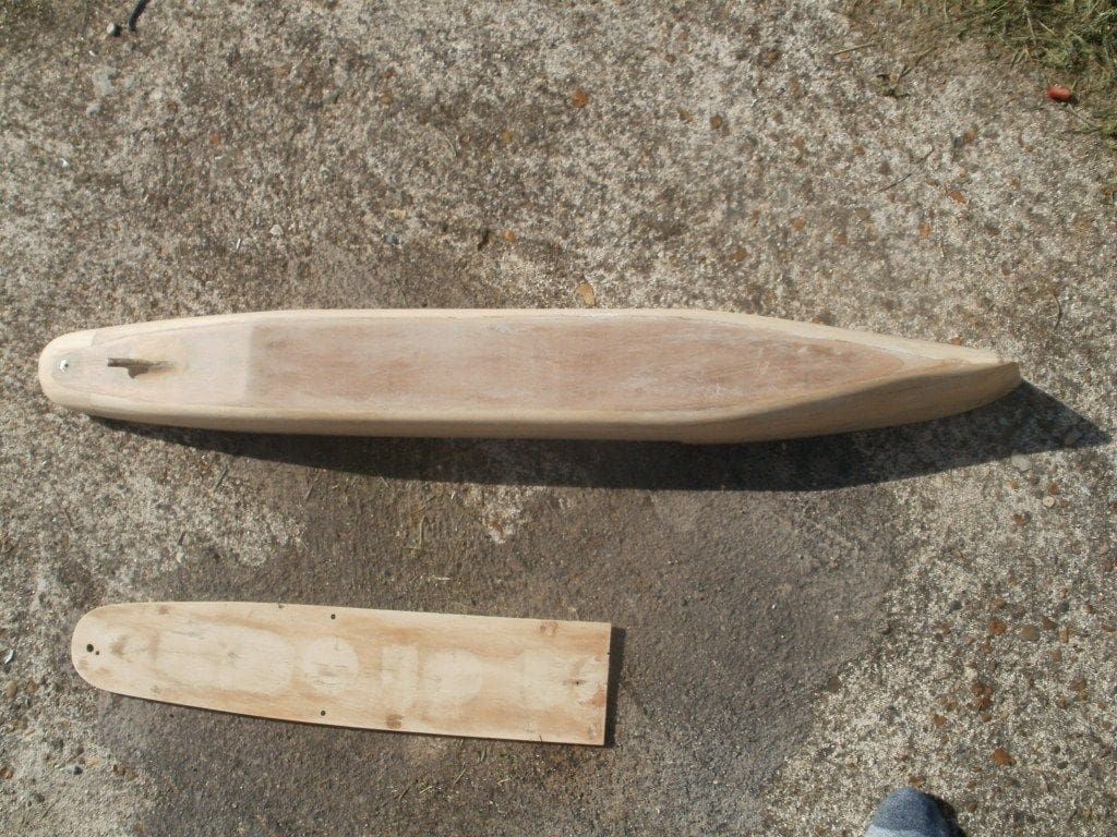
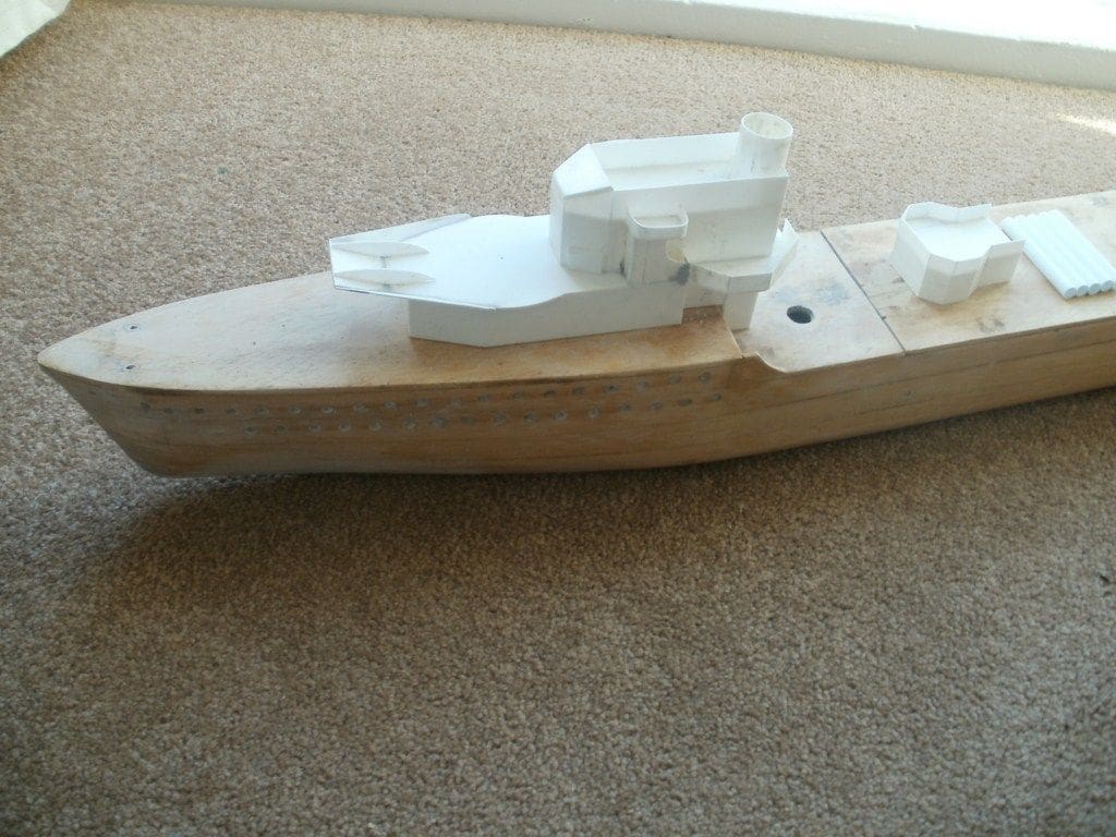
The models as purchased
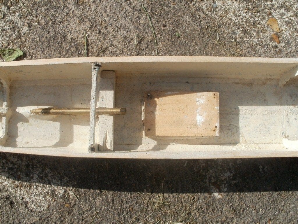
The hulls had been made using the plank on frame method and were quite sound although rough around the edges. The superstructures, as I found out later, were built up from a mish-mash of wood, card and tinplate. The torpedo tubes for example, were made from rolled card, whuch looked like old restaurant menus from an establishment in Glasgow! Perhaps a useful clue as to where they may have originated?
One of the funnels was made from rolled tinplate. The writing, although difficult to decipher seemed to come from some post-WW2 ration tins, thus also possibly a clue to when they were made. The other funnel had been carved out of a solid piece of wood.
Both hulls possessed single very heavy rudders and a single brass propshaft, each without a propeller and they were both without propulsion units which was a bit of a shame. A few days studying them and I decided that it would be better to replace completely all the superstructure components, tidy up the hulls and fit them out for modern electric drive and radio control.
The hulls were about 3 feet long. As the full size versions were about 350ft long we can assume a scale of about 1:100, which is approximate, but sufficient for our purposes.
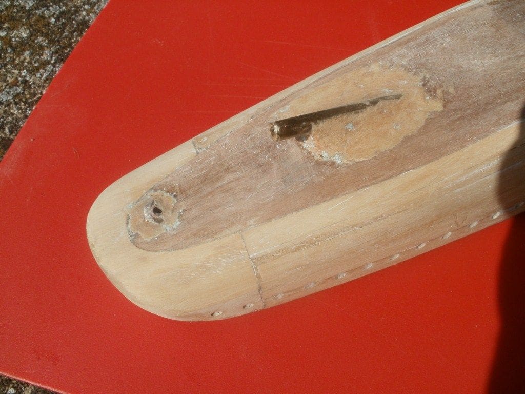
The hulls reconstruction
First, I set about these. The somewhat childlike portholes (which were probably eyelets) were prised out, but I still wanted portholes as they seemed quite prominent on the full sized ships. So, these were temporarily filled with cellulose body putty, allowed to harden and then partially drilled out with a 3/16 inch drill. Yes, slightly over-scale, but the result was okay and certainly better than before. This was only done on one hull as the portholes seemed pretty much in line but on the other they were somewhat irregular so those were just filled in. A tin of Nitromors paint stripper was purchased and applied to the hulls and the old blue paint speedily removed revealing the method of construction. More cellulose putty, wood filler and an electric sander were used to prepare the hulls for repainting. As mentioned earlier, they were relatively sound but quite crudely constructed, so they required quite a lot of work to obtain a decent result.
Unfortunately, removing the superstructures required brute force and resulted in damage to the decks which was rectified using cellulose putty yet again and as the decks would be painted rather than varnished, the finished result would be fine.
The break in the deck line amidships was angular, whereas on the J class the ship’s sides were curved. This was corrected by cementing suitable extension pieces to the hull and blending in with filler. Both hulls were then given a few coats of sanding sealer and thoroughly sanded ready for colour painting later.
Attention now turned to the rudders. The originals were heavy brass and steel affairs and although far from ideal, due to the very robust nature of their construction I decided to use of them anyway. New rudder arms were made from styrene and superglued in place. Each rudder arm was connected directly to a standard servo by means of a contoured brass rod as the hulls were of sufficient depth and beam to accommodate such an arrangement.
Both models lacked a propeller, so I had to guess the size of the originals. These were purchased from commercial suppliers and attached by screwing directly onto the propshaft, secured with a locknut. They are not exactly true to scale, but then little else is either! The propellers are actually twin bladed, but seem to work effectively.
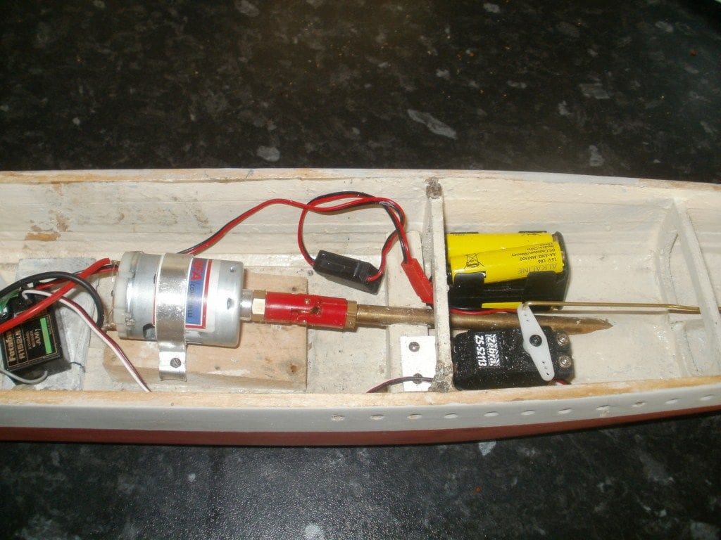
The original motors were missing and it would have been interesting to see what were fitted. Some ancient on/off switches were still attached to the hulls that gave some idea of each model’s vintage. The missing motors appeared to connect to the propshafts via dog drives which were also very heavy and I suspect would have produced a degree of imbalance. So, I installed a single MFA 500 type Torpedo motor in each hull which conveniently matched the new shafting that had been fabricated and installed. The internal motor mounting blocks still remained and as there was a certain amount of misalignment, these were removed and the new MFA motors held directly onto the bases with clamps from aluminium strip.
Each motor was connected to its propshaft using a commercial universal coupling, but it was then that I realised there was a problem with the propeller on one of the models, namely that it fouled the hull bottom. This is where it pays to observe and give proper attention when rebuilding a model!
When I stripped down one of the hulls there was a propshaft tube support which I had left off during reconstruction. I had not noticed that the angle of the new propeller shaft was now much shallower, thus causing the propeller to foul. The builder must have realized this as well and his solution was to extend the propeller shaft to produce more clearance, but requiring a propshaft support. So, I dutifully replaced the support as per original. Unfortunately, I had already made and installed a new propeller shaft which was of course too short, so a new assembly had to be prepared and machined on a lathe.
A nine volt battery appeared to supply more than enough power for the MFA motors and a nice little battery holder was made from styrene sheet. Having basically completed the innards I next turned my attention to the decks and superstructures. Before removing the latter, I had photographed and measured them for subsequent re-building. Once again a trawl of the Internet provided more detailed views of this class of destroyer, so although the same basic outline on the original models had been followed, I modified them further to follow a typical J Class destroyer outline. This rebuild was never meant to produce finely detailed replicas, just very simple, but semi-scale, models.
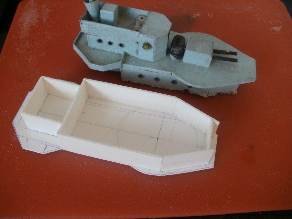
Superstructures
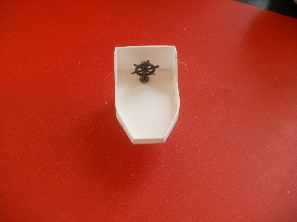
The basic structures were built-up using styrene sheets of differing thicknesses, all of which was very straightforward. This work included the main forward conning bridges, anti-aircraft gun platforms, the rear emergency steering positions and deckhouses.
I found that the easiest way to produce a vertical wall around a deckhouse was to cut out a suitable piece of styrene. then offer it up to an already cut roof. The first vertical angle bend was marked on the sheet, a line scribed and a cut made though about three quarters of its thickness.
The styrene could then be bent and offered back up to the roof and the next bend marked and the process repeated until all the bends had been completed bringing us back to the first end again. By doing it this way there were no gaps to fill on the vertical joints and it was actually very quick.
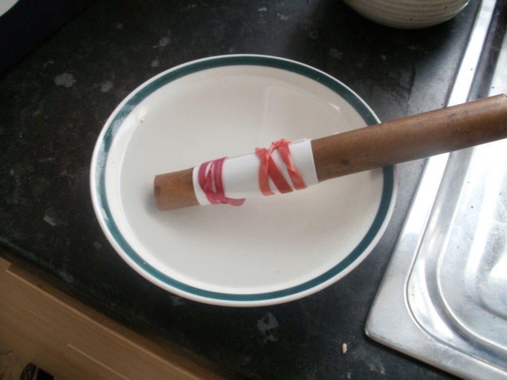
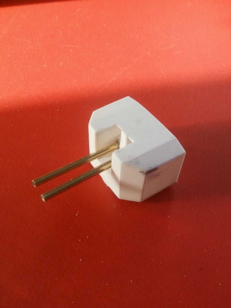
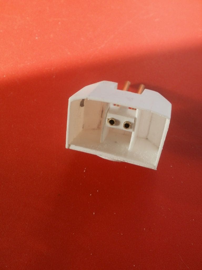
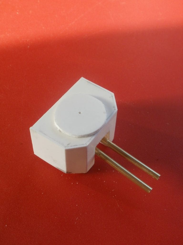
The circular mountings for the direction finders took a little effort to get a decent result. Thin styrene sheet was wrapped around a piece of 18mmm copper tube and held tightly in place with some plastic tape. Boiling water was then poured over it and the styrene sheet thus took up the diameter of the tube. The edges were fettled and adjusted for a good fit and glued together. This tube was then cut away so that it fitted snugly against the back of the superstructure and cemented in place. A small length of the copper tube was finally pushed into the tube to maintain the circular shape and also supported a floor which in turn supported the range finder which was fabricated from polystyrene tube.
Anti-aircraft guns
I like Pom Poms! When you see them in action they are a complete marvel with shell cases flying everywhere and the barrels recoiling, but unfortunately the effectiveness of them did not match this somewhat theatrical appearance. They had a limited range and tended to jam and a multiple Pom Pom also weighed in at a hefty nine tons. After the sinking of HMS Prince of Wales, part of the enquiry concluded that the most effective anti-aircraft weapon had actually been the single barrel Bofors gun.
The J class destroyers were fitted with a quadruple version of the Pom Pom, but these models only had a very poor representation with just two barrels. My versions are not that accurate, but look okay and use the usual styrene sheet for the base and lower body.
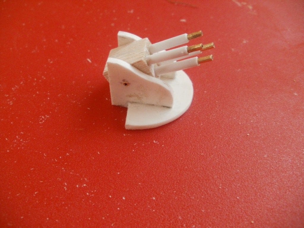
The outer barrels were made from 1/8 inch polystyrene tube with smaller gauge brass tube for the inner barrels. The breech blocks were built up from 3/16 inch square balsa wood with the ends drilled to accept the gun barrels. They can elevate and rotate and look quite nice.
Twin machine guns were fitted either side of the forward bridge and these were constructed in a similar way. Short lengths of styrene tube were cemented together to represent the breech blocks and lengths of brass tube inserted to represent the barrels. The pivots were made from some rectangular styrene section cut in half and the barrels glued to them. The vertical mounting was made by sleeving some plastic and brass tube and gluing it to the base of the mounting. Each was then glued to the side sponsons.
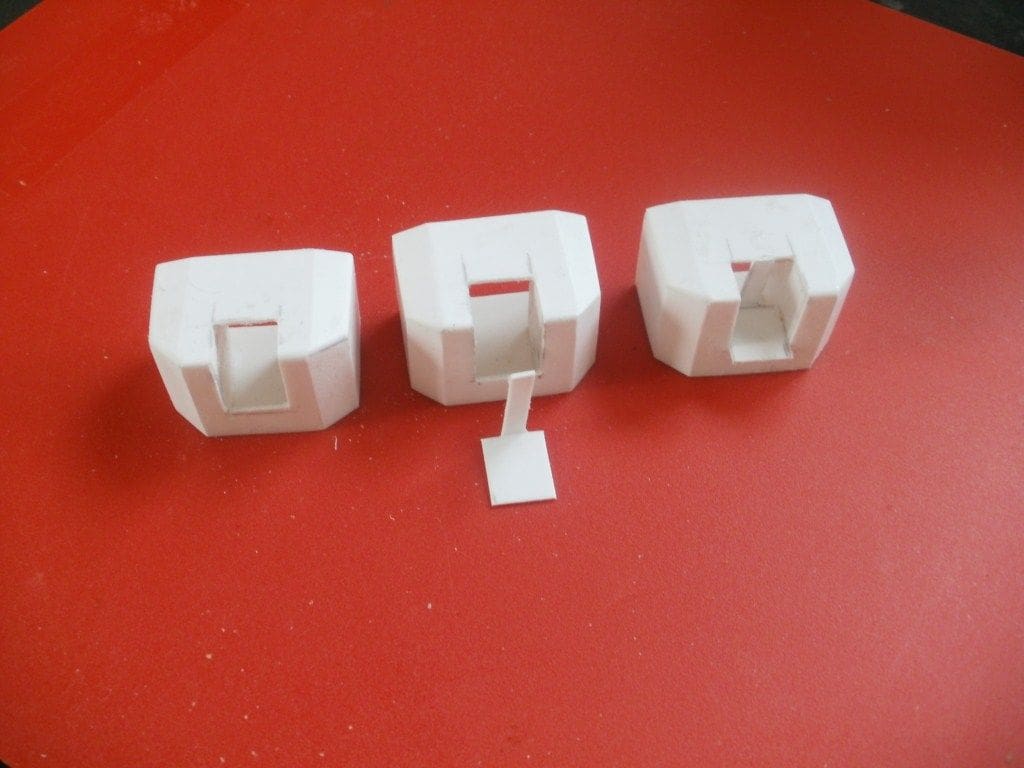
Main guns
The J class destroyers were fitted with six 4.7 inch guns in three twin mountings. They were protected with shields, but could not really be called turrets as there was no rear armoured wall and the ammunition did not move with the guns, these being hand loaded. The mounting of the rear twin mounting was slightly unusual in that it did not face astern. It was mounted to face towards the bows and could not fire directly aft.
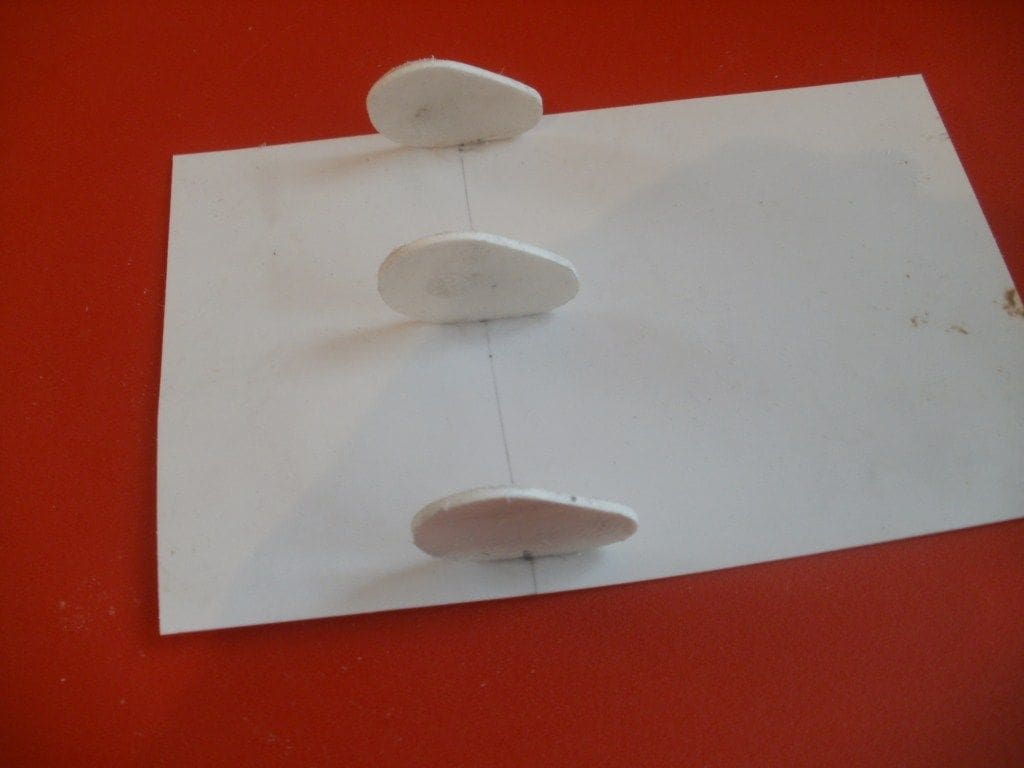
I made a start with the shields as the model guns were very poor and could not even be used as a pattern. So, using various photographs, I just guessed the correct size. It was too difficult to bend the styrene, so in the end a basic shape was used but angled rather than rounded corners were installed.
The main body of each gun shield was made in the same way as the sides of the superstructure deckhouses. Once the glue had hardened, an opening for the guns and internal dividing plates was made. After tidying things up I was quite pleased with the result, but as always repetition is a pain as I had to make six mountings in total for the two models.
The barrels were constructed from 3/16ins brass tube cut to length. There was no profiling and the breech blocks were made from rectangular section styrene. A length was cut that fitted snugly within the dividing plates and the position of the barrels marked. Suitable holes were drilled and the barrels pushed in and superglued. The complete units were then inserted from the rear and a spot of glue secured them in position. They cannot be elevated but do have a slight elevation that looks okay, however the mounts do rotate. For this, a support platform was cut from styrene sheet and glued to its base which was drilled centrally for a 6BA bolt. A corresponding hole was drilled in the deck. Depending on which turret, either a 6BA brass bolt was inserted from below or a length of 6BA threaded section glued to the deck, and the turret could be screwed onto it. Either way the turrets are able to rotate quite freely.
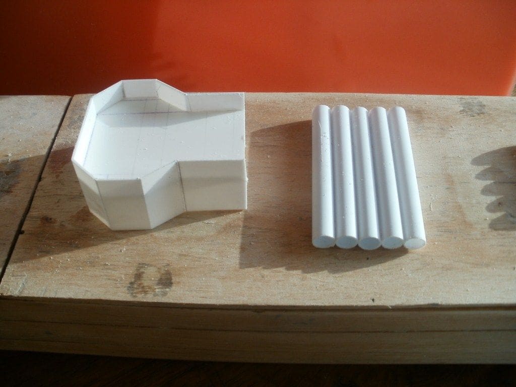
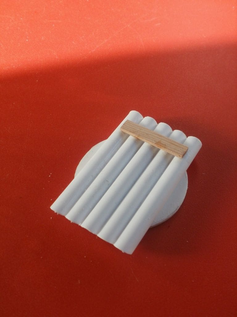
Torpedo tubes
There were two banks of five torpedo tubes on the original J class which were copied using 3/8ins styrene tube. The pieces were cut slightly longer than necessary and firmly cemented together and once set, were cut to length. The rotation platforms were cut from polystyrene sheet and again pivot around a single 6BA bolt. Additional detailing was added from styrene sheet.
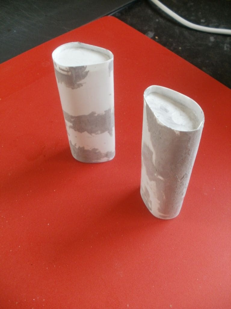
Funnels
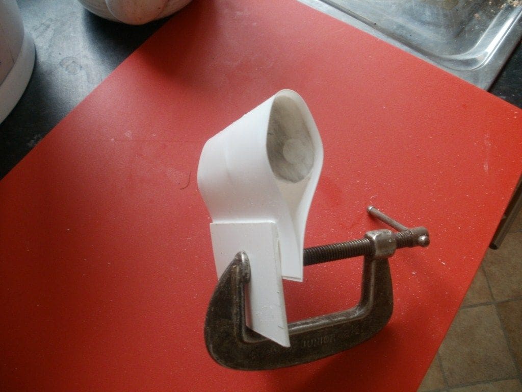
The originals were really not very good so new ones had to be made. There was a choice of materials, but styrene was selected once again as I was beginning to be quite adept at manipulating it.
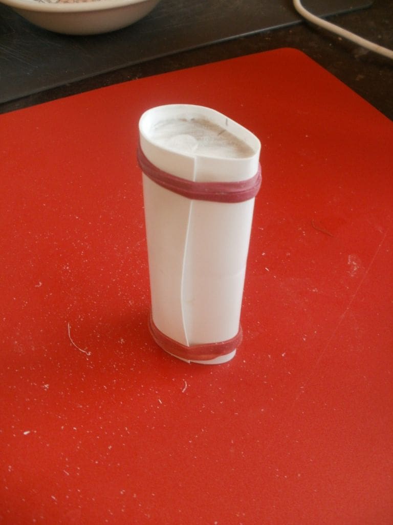
Internal frames were cut to a profile that I thought looked about right. Very thin styrene sheet was then glued over these and this had to be done in stages. To attain a nice smooth surface a considerable amount of filler had to be used. This was because the sheet was so thin it was dissolved by the polystyrene cement and the elastic bands I used to hold it in place cut also cut into its surface. So, another lesson learnt! Always use the thickest sheet that you can manipulate to avoid this problem.
The funnels were supported on a small box like section that was cemented to the rear of the main superstructure. There were two steam lines that passed up the front of each funnel. I think that these were the safety valve exhausts from the main boilers and were represented using styrene tube cut, bent and glued in place.
Searchlights
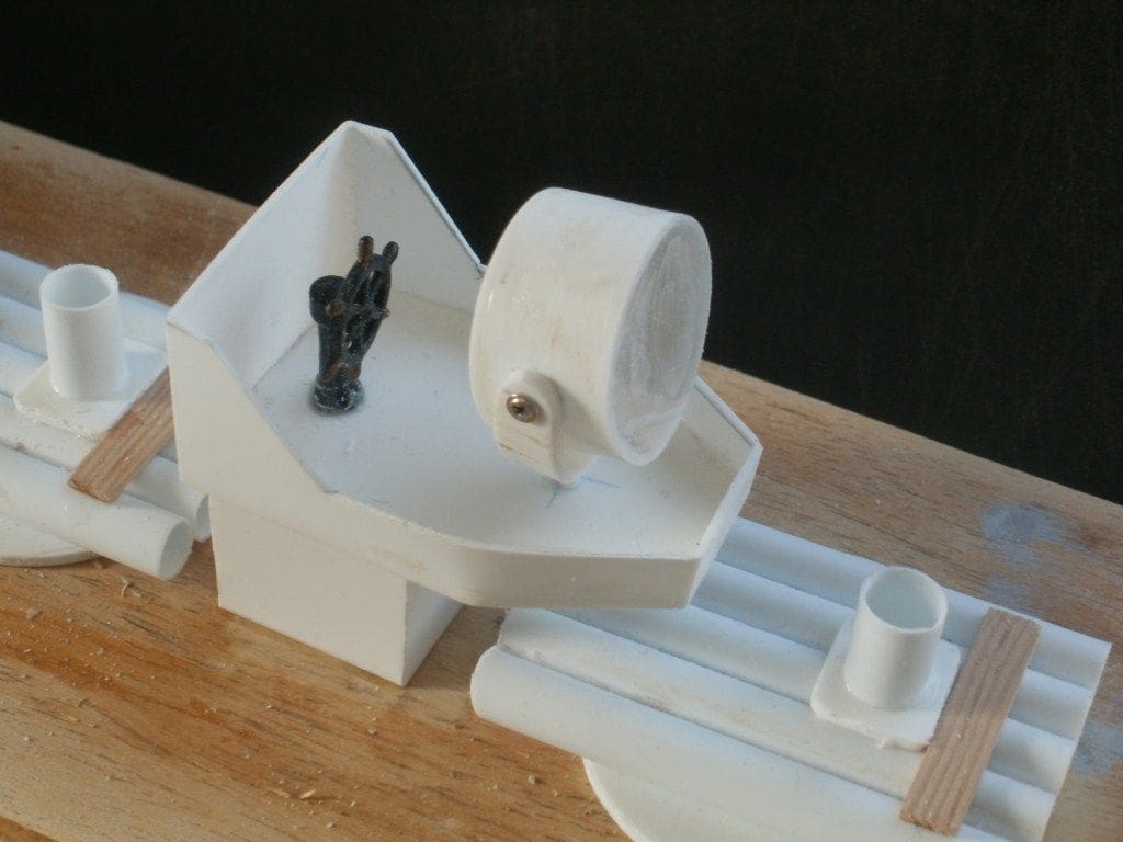
The J class destroyers had a few of these, which included a big one on the rear emergency steering position and smaller ones either side of the bridge.
The smaller types were simply fabricated from 3/8 inch styrene tube fixed on pedestals. The lenses were from thin acetate sheet cemented in place. Once again the overall effect is quite good. The larger searchlights were fabricated in a different way with the main body from rolled styrene sheet. The back plate was also made from styrene and the lens from clear acetate sheet. A simple pivot allows the whole thing to elevate and rotate.
Depth charges and other fittings
The racks were fabricated from styrene sheet and T section. The depth charges were made as one single piece, just being lengths of 3/8ins OD styrene tube cut and glued together with their ends were blanked off by a single piece of styrene strip contoured to shape on each side. On reflection, making them individually would have produced a better result.
Rope reels were made in a similar way and bollards by gluing short lengths of tubing into a base plate.
The liferafts were an interesting challenge. 3/16ins styrene tube was cut to length and assembled to form a rectangle. A floor from thin styrene sheet was then glued underneath this rectangle and the edges rounded. The end results looked something like liferafts which were glued to the sides of the front and rear superstructures.
The main masts were from brass tube. Photographs of the time seem to indicate tripod masts so the necessary pieces were cut to length and soft soldered together with cross spars and crows nests added later.
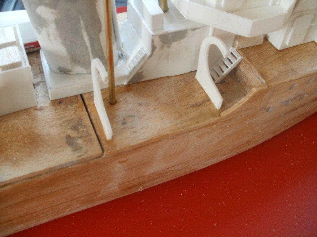
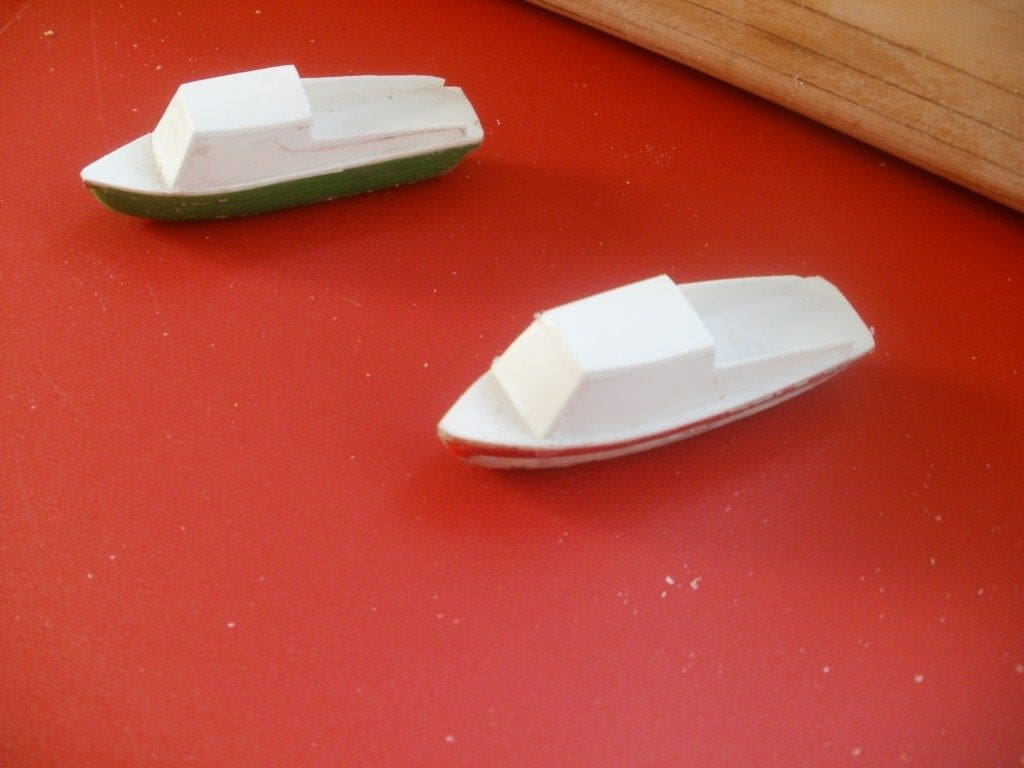
The ship’s boats were a bit of a problem as those that came with the models were incomplete and not very good either, so what to do? To start with, the davits were constructed from styrene sheet. I think that the original vessels would have had perhaps four boats, but I felt that two would suffice as these were just semi-scale models. Two, which were just open rowing boats, were selected from the original un-restored models. Decks and cabins were added, thus giving them the appearance of motor launches and they were glued directly to the davits with dummy support ropes. The other pair of boat were made by modifying some from a Revell Kearsarge kit. Now, the bulk of construction was complete, the models just needing odds and sods such as anchors, rigging and railings to be added.
A word about the railings might be useful at this stage. I had removed the originals and intended to replace them with new ones, that is until I saw the cost of replacements, so I decided to refurbish the originals.
Replacing the stanchions was bad enough when just trying to get them upright with the eye holes pointing in the right direction. Threading new nylon railings was something else! It was like threading a hundred needles and it took hours, but was accomplished in the end, but not without the usual superglue drama. I had just finished threading one of the railings and was gluing the end to the deck and as I moved my hand away found the end of the railing attached to my digit rather than the deck. That movement pulled the railing completely out of the stanchions and thus I was back to square one! Anyway, with teeth gritted the task was eventually completed on the first model, just having to be repeated on the other.
Painting
This had not been done as work progressed, so it was now time to paint the models. Fortunately, being not too detailed, this was straightforward enough. White Ensign Models, WW2 Light Grey was used for the hulls, weapons, detailing and superstructures, with a darker grey for the decks and the below waterline anti-fouling in the usual red.
Sea trials and conclusion
It was then time to give them their first sea trials. The original models had heavy lead ballast weights but I suspected that yet more weight would be required to get the correct displacements. The usual bath trials and necessary corrections were made before setting of to the pond and it was surprising how much ballast was actually needed to keep them upright. I can only assume that as originally built they must have been very unstable.
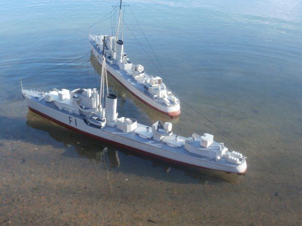
By using the same r/c frequency in each boat and operating only the rudders I hoped to be able to control both boats with the one transmitter and at the same time for a sort of squadron sailing. The theory sounded fine but I did wonder how my brain would react to having to coordinate two boats with just one rudder control! To date this has not been tried properly – I rather suspect that each model will perform slightly differently and very rapidly they will be going in different directions and be at opposing ends of the pond.
Anyway, I have to say that the end result was actually two rather attractive semi-scale destroyers. Yes, somewhat simplistic in design, but overall not too bad and I was (and am) happy, which is the main thing.