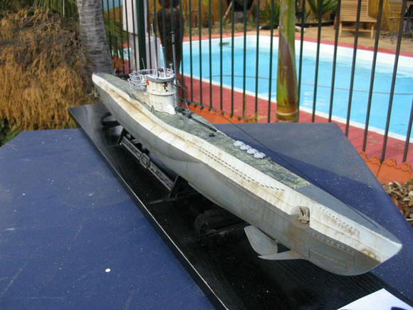
After converting a Revell Type VIIC U-Boat (U-96) to a surface running R/C model earlier this year, Photos 1 and 2, I wanted to take the next step in the model submarine evolutionary ladder and build a diving model. Now we’ve all read previous articles about converting the Revell kits into dynamic diving models by creating a water tight area in the hull and using the deck as the seal (in particular Model Boats January 2006 issue). Well I’ve decided to go one step further and build a separate and removable water tight compartment or WTC. Now my technical knowledge is pretty limited when it comes to creative engineering but it pays to have good friends who know what they’re doing in this field. Wayne Baker, builder of the 1:72 scale scratch built HSV-X1 USN Catamaran not only assisted in designing the WTC; he pretty much built the crucial parts for it as well. The kit I chose to convert was the latest Revell release of the Type VIIC/41 Atlantic U-Boat. Now, from the start I wanted to have a completely flooding hull and working dive planes on this model so I began cutting out each and every flooding hole in the plastic hull and fitting levered brass tubes for the bow and stern dive planes. This needed to be done before the hull could be glued together, Photos 3 and 4. The brass ‘lever’ will be connected to the servo push rod later and the dive planes will be inserted into the tube from the outside. I also chose to follow Keith Bragg’s advice (Model Boats January 2006 issue) and built larger bow planes to affect an easier dive, Photo 5.
Article continues below…
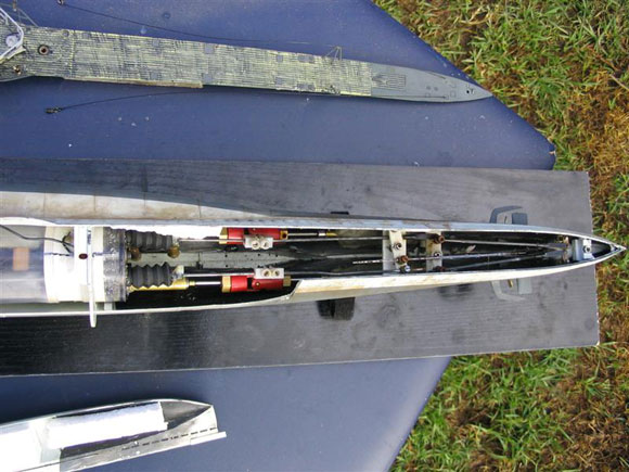
Enjoy more Model Boats Magazine reading in the monthly magazine. Click here to subscribe & save. During the long and laborious task of cutting out all of the flooding holes in the kit’s hull, Wayne and I worked on designing and building the water tight compartments for each of our models. Photo 6 shows our final design. For the clear tube we used a fish tank vacuum tube with a 40mm PVC inner tube as a tray cut in sections to house each of the internal components. After that it was time to plan and organise just how to hook up the rudder posts and dive planes with the two sets of push rods coming out of the WTC. Photo 7 and Fig 8 are an attempt to illustrate how I’ve done it. With this setup the dive planes work opposite each other, meaning that when the bow planes produce ‘down force’ the stern planes produce a bit of ‘up force’, making it very easy to dive the model. The next hurdle was to sort out how I was going to easily insert and remove the WTC from the model. In what initially was a drastic move I decided to cut away the port side, mid section of the model, following the lines under the ballast bulge of the U-boat casing. Photos 9, 10 and 11.
|
|
This made it really easy to insert the WTC and slide the rear end of it into the larger bulkhead, lining it up with the prop shafts. To hold the cut section in place during sailing I simply glued thin strips of styrene along the bottom edge and at opposite ends of the section that easily sat behind the main hull sections, providing good stability and form. I honestly think that this was the only way to accomplish my goal. It required minimal cutting and the cut lines can be hidden with a good paint job and ample weathering. Next hurdle to conquer was that of buoyancy and trim. Now I’ll admit that my U96 as a surface running model sits too high in the water. Well I didn’t want to hide any of it. This model’s buoyancy is more a matter of function than stage presence so I aimed to have the decks sitting just above the water, providing the sub with a slight positive buoyancy. Handy in an emergency! See Photo 12. This was a lot harder to achieve than I expected. I didn’t realize just how much weight was in 7 x AA batteries. This thing sank like a stone. To combat this strangely non submarine like characteristic I needed to add floatation instead of ballast. I used pieces of polystyrene foam, fixed to the underside of each section of deck as well as tucking some inside the ballast bulges of the casing. I spent literally days placing, moving, removing and cutting polystyrene to get the level of buoyancy and trim that I was after. The effort paid off in the end, Photo 13. Now, what came next?Oh yeah, diving tests. I consider myself to be your average modeller and that means getting the thing in the water and working properly before I actually finish building it. To that end I had to fasten the deck sections down with elastic bands during testing so that they didn’t float away. Photo 14 shows the first day’s testing in my pool, sorry test tank. Again, I needed the help of Wayne Baker to drive the sub while I took the photos. I had a go later. To say that this was fun is a gross understatement. I found it so much of a challenge to think and sail in three dimensions that I didn’t want to stop. Unfortunately the batteries needed a rest after about 20 minutes of full throttle and reversing so I had a break and celebrated with a beer or two. This model performed amazingly well. After I made some minor adjustments on the dive plane angles she dived really easily with not that much throttle and cruised nicely along the bottom of my pool at a depth of four feet.
|
|
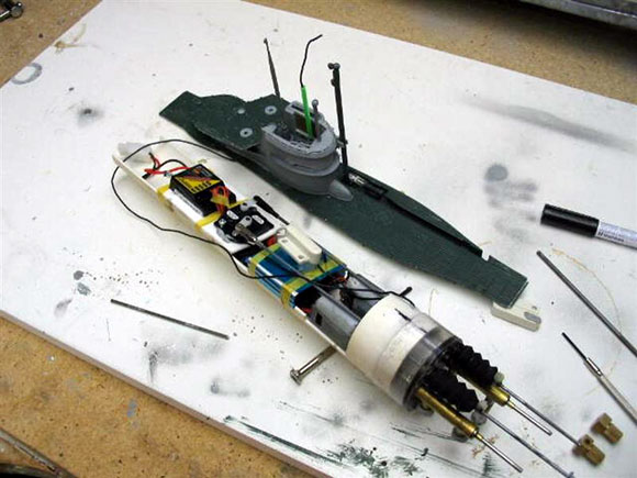
The only issue that did become apparent during these tests was that radio reception dropped out every now and then later on during submerged cruising. So I had to mount the receiver antennae as high on the model as possible to combat the distortion effects of the water’s density. The best way to do this was to run the antennae wire up through a tube in the conning tower. I made sure to seal the top of the wire so that water doesn’t come in contact with any bare wire. The tube I used will be painted to look like it’s meant to be there. Photo 15 shows how the PVC tray is removable from the clear tubing of the WTC. She works in the pool but does she perform as well in the Hubertus MBC lake? You’d better believe it! See Photo 16. I didn’t sail her too far away from shore though, just in case. Reception of the radio receiver seemed to be excellent with the antennae poking out of the conning tower. Also, with less full throttle and reverse sailing as happens in my pool, running time was extended to almost a full hour. It’s now time to finish the building and give her a name. After searching the internet for ‘U-boat emblems’ I decided upon the pendant number of U324. Not much of a history but a really nice shark emblem that just happens to be included on the decal sheet for the model. To finish off the model I added the rigging using craft jewellery wire and barrel clasps. For weathering I applied real rust using my own method of brushing on the remnants of a very old and rusty steel wool pad. This is by no means the only way of converting this wonderful kit into a dynamic diving model submarine but it works and works well. In having a separate and removable WTC you can build a number of these kits and interchange the compartment to sail the model of your choice. That means you can build your very own Wolf Pack and really rule the lake. If you would like more details about the construction of the WTC Wayne and I have built for this submarine don’t hesitate to contact me via my web site www.pier72.com. I have learnt so much during the construction of this model that I would love to pass on any advice I can to those who are willing to give it a shot. Just don’t be surprised if your friends start calling you a ‘bubble head’ once you start building it. The only problem now is deciding on what to build next! Happy modelling.
|
Dynamic Diving!
by
–
Advert
Enjoy more Model Boats Magazine reading every month. Click here to subscribe.
Article Tags:


