By ALAN FURNESS

Whilst some modellers prefer to use preformed GRP or plastic hulls and styrene sheet for the superstructure of their boats, others including myself are dedicated to the use of wood for the hull, most of the superstructure and many of the other components needed to complete the model.
Enjoy more Model Boats Magazine reading in the monthly magazine.
Click here to subscribe & save.
The idea
I have never seriously contemplated straying from the use of wood for the construction of my models, that is until a relatively recent event caused me to consider employing metal for cladding the hull and possibly the superstructure of a future build. This unusual train of thought arose following the receipt of instructions from the ‘management’ to clear up the alcoholic debris after my 80th birthday party in July 2009. The task involved collecting and disposing of a modest quantity of empty wine and spirit bottles and a somewhat larger number of empty beer and other drink cans.
Disposal of an apparently useful commodity such as these lightweight aluminium cans and the ease with which they can be distorted and then regain much of their original shape by reversing the distortion pressure, caused me to wonder whether or not this high degree of metal flexibility could be usefully employed in our hobby, particularly when cladding the more difficult shapes that sometimes occur with some designs of model boat hull.
Thus what became the concept of the ‘Beer Can Boat’ began to take shape in my mind. It envisaged possible savings in building material costs for modellers, also a potential weight reduction that would arise from the use of thinner aluminium hull cladding. In addition we would be recycling the cans for our benefit, rather than collecting the scrap simply to help swell aluminium industry profits.
The theory
Having spent 50 years as a metallurgist in the aluminium industry, I am familiar with the wrought alloys used for can production. One of the 3000 series manganese containing alloys is used for can bodies, with one of the 5000 series magnesium containing range for the can lid with ring pull. The fabrication process by which cans are formed, is a highly complex automated mechanical operation producing thousands of units per hour and would take a lot of space to explain here.
However, the recycling operation by which scrap cans are returned to usable metal is worth a mention. It starts with shredding the whole cans and burning off of the external paint and internal lacquer coatings. This is followed by bulk melting, alloy correction, then casting the liquid metal into large blocks. These blocks then go through multiple rolling operations to arrive at the required sheet thickness for can forming. Here I must be point out that scrap cans of the wrought aluminium alloy range, are totally unsuited to DIY melting and casting. If this activity is of interest to the reader he must accept that for good results, one of the designated range of casting alloys should be used.
Over the years, the thickness of can body material has been gradually reduced to provide cost savings for can makers and brewers, from reduced metal consumption. This has happened to such an extent that if the external paint and internal coat of lacquer were to be removed, only the pressure of the residual liquid would be responsible for maintaining the shape of the can, rather than the strength of the metal.
Having theorised at length regarding the possibility that aluminium sheet recovered from used beer or soft drinks cans could become a workable and economically suitable substitute for thin plywood, it was evident that the next step for me would be to set about proving it by building a model involving the use of this material. Construction work on such a model actually started on 26th April 2010.
Putting theory into action
I have long been a builder of Free Plan models, which is a subject discussed at length in my article that appeared in the March 2010 edition of Model Boats. Thus, I turned to my reference file of past unbuilt free plans to see if there was one that would be suitable for the first experimental ‘Beer Can Boat’.
I finally selected Glynn Guest’s Emily May freighter, as the boat to build for this experiment. It appeared as a Free Plan in the October 2007 edition of Model Boats and I selected it on account of the complex shape of the hull, as it represented a good test regarding the flexibility of thin aluminium. I have a high regard for Glynn’s work and also the fact that he himself builds each model shown in his plans, prior to publication. He also thoroughly describes each stage of the work in an accompanying article.
Before starting the building programme I checked the relative weights of representative panels, cut from aluminium can sheet, also sheet from the same size of steel can which is used exclusively by one well known brewer. Two grades of thin ply I often use for cladding i.e., 0.87mm thick and 1.25 mm thick were also included in the checks. The weights are shown in the accompanying Data Table. In addition I checked the various sizes of can and their weights as applicable to my own choice of beer, plus those of soft drinks and lagers popular in our family!
It was evident that some testing of suitable adhesives would also be necessary, if the possibility of leaks at joints between aluminium panels and wooden frames were to be avoided. Contact adhesives appeared to be strong contenders for this job, with the possibility that Araldite might be a useful alternative. Superglue was also tested, but initially discounted on a cost basis, because of the large quantities that were likely be needed due to end grain wood absorption.
Hull framework
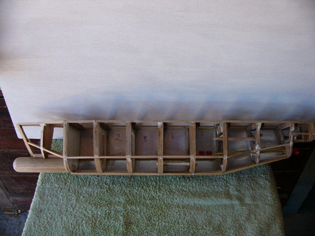
At the start of building operations, a duplicate set of frame members were cut from 3mm thick ply. The initial set were mounted on an MDF building board at the appropriate spacing and 3mm square hardwood stringers were used to tie the frames together.
As anticipated, the 3mm frame thickness was not wide enough to allow adjacent panels of aluminium to be easily stuck to the frames, thus the spare set of frames were glued to those mounted on the building board. This now provided a satisfactory 6mm wide frame surface on which the adjacent aluminium panels could be accurately glued to the wooden framework, Photo 1.
Plating the hull
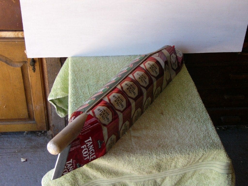
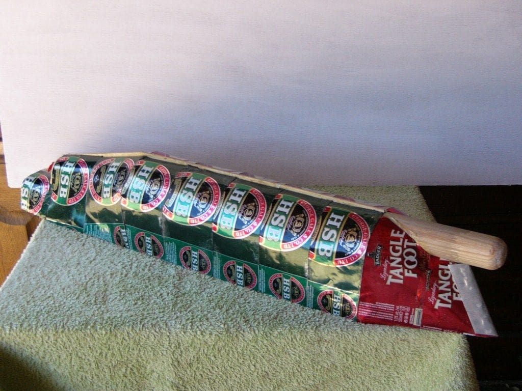
As the work progressed, it became clear that contact adhesive had not been the best choice, due to the difficulty in removing residues from metal and wood, plus the slow setting time. Also, it was found that failure to fully remove all the lacquer film from the edges of the internal can surface with sandpaper prior to gluing, inevitably lead to an unsound joint. At that time, a change to Araldite was impossible and contact adhesive continued to be used until cladding of the hull was complete as seen in Photos 2 and 3. They also show my affinity for three brands of ale that helped make the project more interesting. Any can shortage was simply solved by purchasing another six pack!
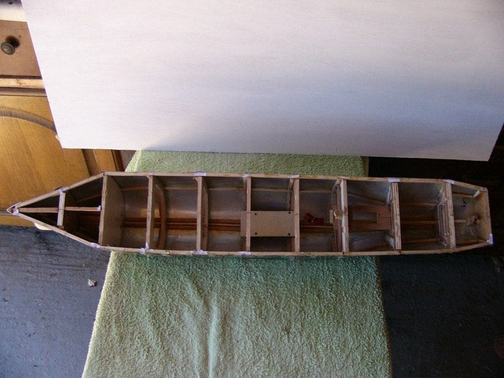
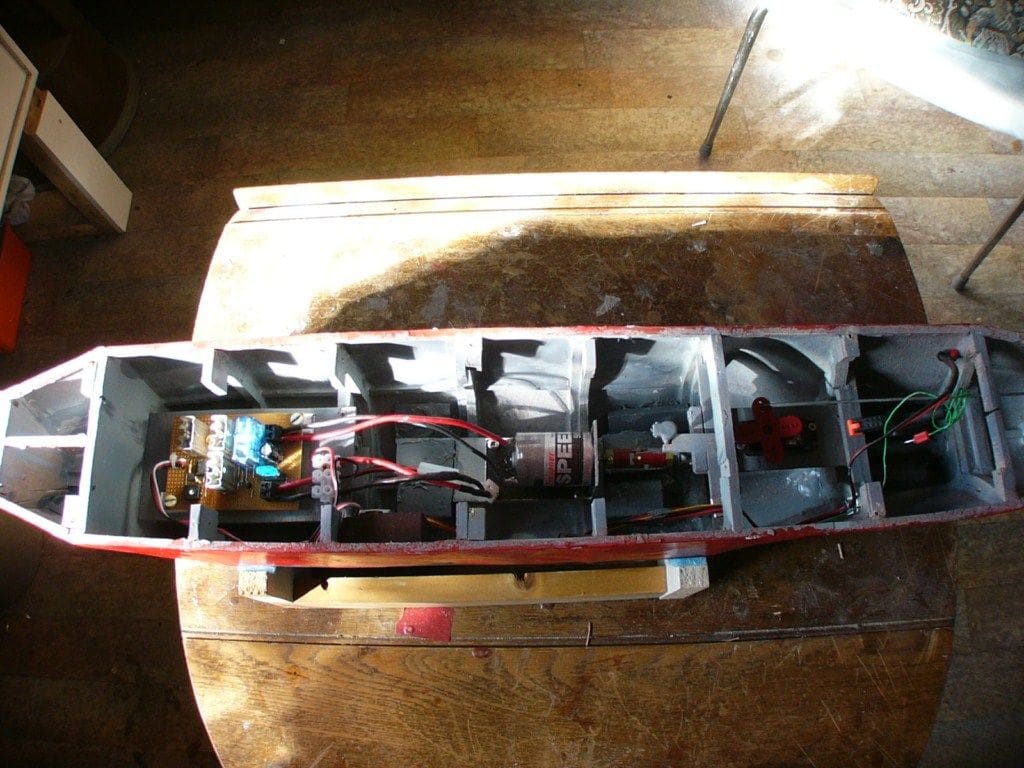
Experience and a few past leaks have shown that it is really worthwhile applying a light coat of quick setting resin over much of the internal surface of the hull, before permanently installing the motor, wiring, servo and electronics. This is also the best way of preventing leaks around the propshaft, at the point it passes through the hull woodwork, or in this case, the aluminium sheet. Photo 4, is a view of the internal hull with drive shaft installed, following completion of the cladding and also after resin coating.
Photo 5, shows the layout of the motor, esc (built for me by our club’s electronics specialist), also the wiring, rudder servo, etc. You might just be able to see the cap on the propshaft oiler tube. I always solder a feed tube and oiler into the top bearing to provide lubrication and the oil also prevents water coming up the shaft. Prior to these installations, the external surface of the hull was given two coats of red zinc oxide paint followed by a rub down, then three coats of matt black paint below the waterline were applied and then two coats of red undercoat, followed by gloss red, for above the waterline.
Decks and superstructure
It was now necessary to consider what materials to employ for building the deck and superstructure. The deck could quite easily have been constructed from aluminium can metal on a 3 or 5mm square hardwood frame, but there is always a need to remove a part of the deck to gain access to the drive system. Also a platform for the cargo of containers was required, as well as removal of the superstructure to gain access to the servo and rudder. In view of this, it seemed sensible that the deck and coaming to prevent water entry, should be constructed from 2mm thick plywood.
However, for the actual superstructure it was decided that this should be built of can aluminium on a wooden framework, instead of either thin plywood or card as suggested in the article which accompanied Glynn’s plan. To produce a realistic appearance, it was essential that a number of windows were formed in the superstructure and particularly on the bridge. Thus, these would need to be formed in the aluminium panels prior to mounting them on the pre-constructed wood framework.
Windows
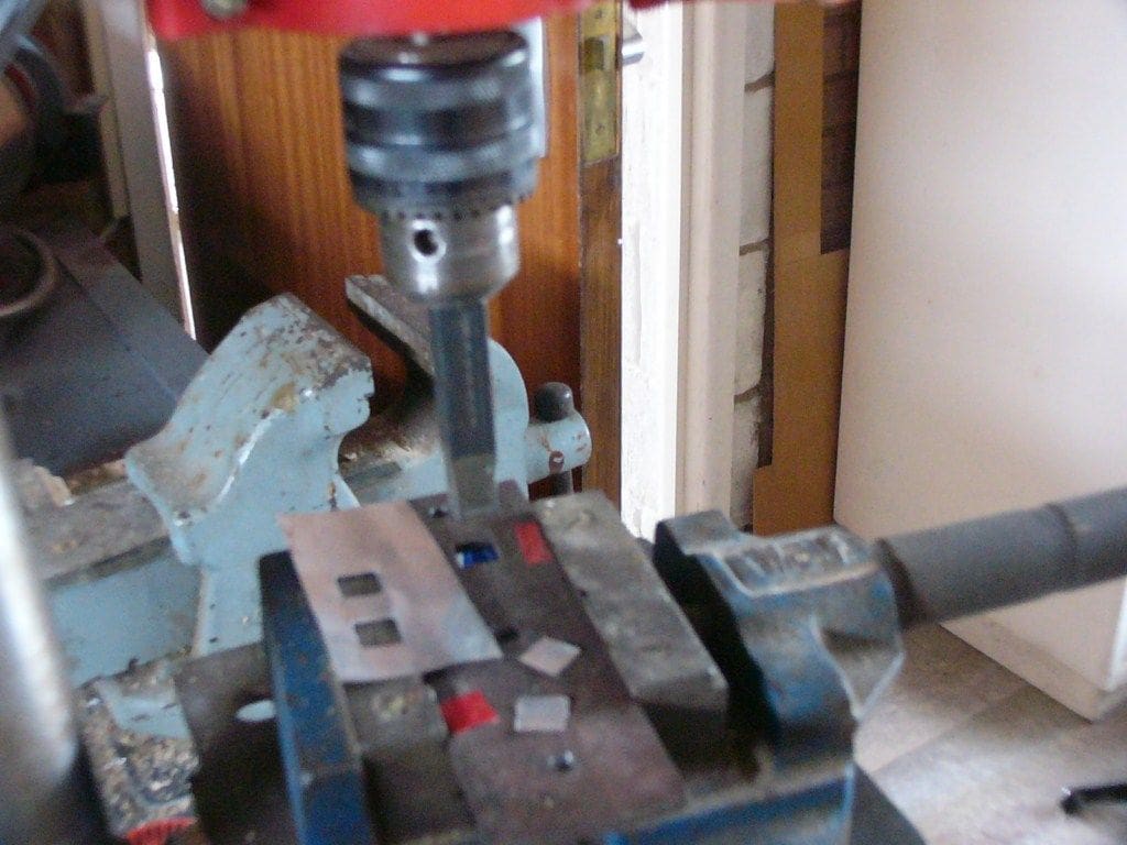
To produce the large number of windows required in a previous model of a pre-war ocean liner, also designed by Glynn Guest, I had fabricated a punch tool. This was made from an old drill with its end ground to 4mm square and a steel base plate in which a 4mm square matching hole had been accurately cut. This had worked well on 0.87mm thick plywood and 1.5mm Lite Ply when operated in my pillar drill, so I decided to repeat this, using a larger tool size of 10mm square to match the windows shown in the Emily May drawing.
The punch worked well on the thin aluminium metal, and it was possible to accurately produce the required window pattern according to the Free Plan drawing. Photo 6 shows the window hole punch installed on my small pillar drill, with a sample of the holes produced. It should be possible to operate this type of punch without a pillar drill, provided another method of keeping the punch and base plate accurately lined up is employed and a hammer or other tool is used to activate the cutting force.
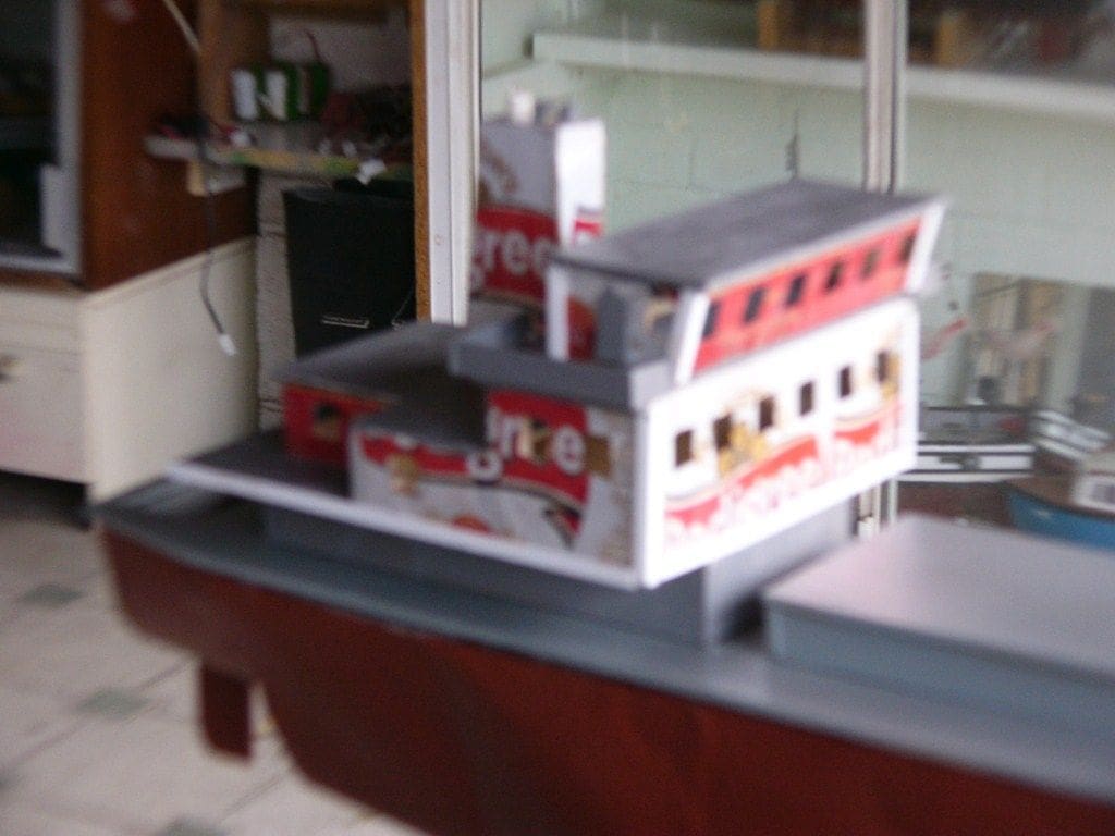
The superstructure and funnel, also clad with aluminium was then completed, but instead of using contact adhesive to make the joints between the wood and the de-lacquered aluminium, superglue was satisfactorily substituted. Photo 7, (somewhat blurred unfortunately) shows the finished but unpainted superstructure and identifies another of my favoured beer brands!
Whilst building the superstructure, sufficient access had been left to enable thin transparent plastic sheet windows to be installed on the inner surfaces. This rather delicate job was carried out after spraying the exterior and interior with two coats of matt white paint. The external deck surfaces were then given two coats of matt dark green paint, prior to fixing the funnel and various rails, ship’s lifeboats and the davits, these last made by cutting narrow half sections from white 20mm plastic plumbers pipe.
Other fittings
The next task was to construct the two masts according to the plan, as well as the forward deck equipment including the winch, anchors, steps and railings. Also, a number of punched out 10mm square pieces of aluminium to act as reflective windows, were glued to the lower wooden superstructure and several dummy doors in white plastic sheet were also fitted. Other deck fittings such as fire hydrants (fashioned from thick red electric cable) and fire hose made from coiled thin red cable were mounted at appropriate points. A searchlight, radar, and satellite dish were also added to the upper superstructure.
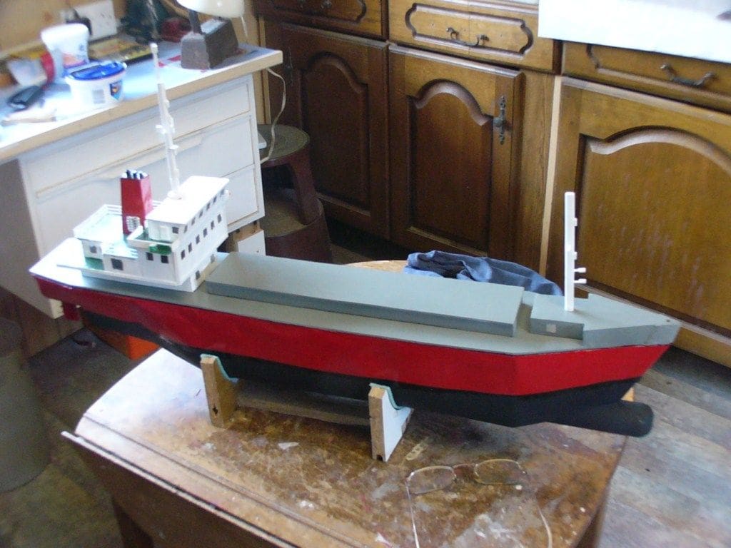
With construction of Emily May now nearing completion, Photo 8, it seemed important to check how well she would behave in the water and what ballast would be needed to achieve flotation at the correct waterline. When we had a bathroom refit a couple of years ago I retained the old bath as a test tank and this is installed at the rear of my workshop for carrying out flotation testing as needed. I always keep a check on the total weight of each model that I build and also its basic parts.
In this case, the hull of Emily May after fitting out with motor, electronics etc. weighed 1.8kg, the superstructure and deck, plus containers and cranes to be described next, weighed 0.763kg. To gain a reasonably balanced flotation level, 1.3kg of lead was added at various points in the hull and secured in place with bathroom silicone sealant.
Deck cargo
The next task was to construct a number of shipping containers to be installed as deck cargo. It was intended that these too should also be constructed from can sheet, but the changes to the metal structure brought about by sheet rolling and can body formation, were such that it proved too difficult to form the 25 x 30 x 80mm long square edged shapes with any degree of accuracy.
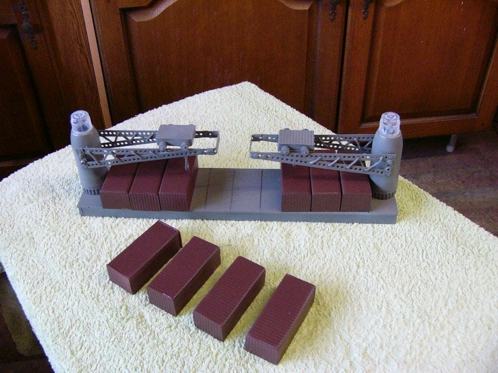
As a compromise, 9 containers were built from 1mm thick ribbed aluminium sheet, which looked more realistic than smooth can sheet, but they weighed 22 grammes each. In view of limited space, the two cranes shown in Glynn’s drawing of Emily May were repositioned at each end of the container platform, which matched reasonably the deck designs seen on a number of ships at sea during a recent cruise to the Black Sea. The crane bodies were constructed from plastic prescription only Symbicort breath enhancing inhaler bodies, topped with perspex domes, plus gantries formed from perforated metal strip and each weighed 7.5 grammes. The cranes and containers are shown in Photo 9.
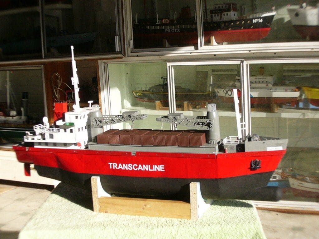
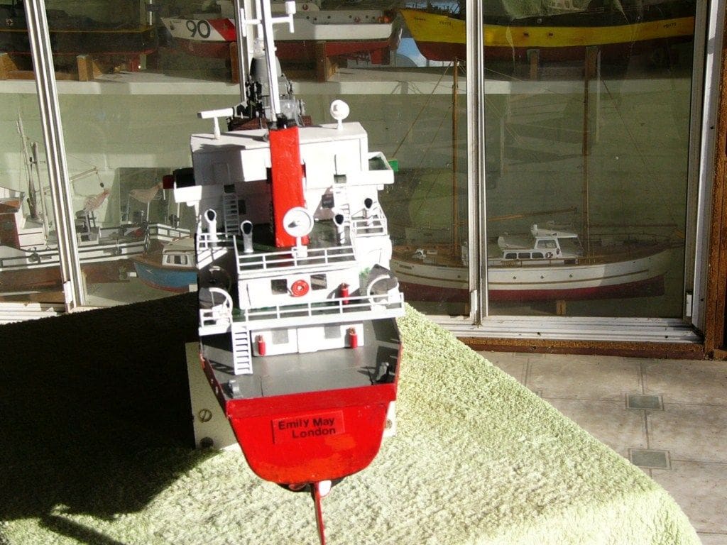
Finally, on the 7th Nov 2010, after 195 hours of construction work, the Beer Can Boat was finished, Photos 10 and 11, its all up weight now being approx 8.5kg. including drive batteries etc. However, a further bath test revealed that the higher centre of gravity and weight increase from the deck containers and cranes, required a 0.25kg lead keel to be fitted externally to ensure a balanced floating model.
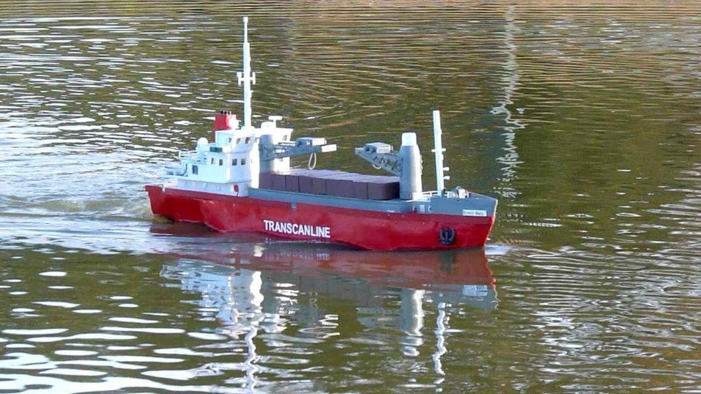
On the water
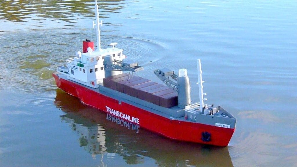
The only remaining task was to test the sea keeping capabilities of this somewhat modified version of Glynn Guest’s Emily May. This was finally achieved at our Solent RCMBC sailing venue of Setley pond in the New Forest on the 8th November 2010 and the result can be seen in Photo 12.
Conclusion
It’s is fair to say that aluminium sheet recovered from scrap beer cans can be a successful substitute for the increasingly expensive thin plywood that has historically been used for cladding hulls and superstructures of wooden model boats. After removal of the can ends, the usable metal has the added advantage of being able to be cut with a sharp pair of scissors. If one wishes to minimise the weight of a craft like those used for fast electric racing, then aluminium can metal offers a better than 50% weight saving over thin plywood and costs even less, if you have first enjoyed the can contents!
Lessons learned from the experimental building of the Beer Can Boat Emily May, include the importance of selecting a suitable adhesive to secure aluminium to wood, the removal of the internal lacquer coating and exterior paint where metal to wood or metal to other dissimilar materials joints are to be made. Superglue can successfully be used to join aluminium to wood, provided that both surfaces are clean and free from paint or lacquer. The end grain absorption of superglue on plywood frames can be minimised if a priming coat is applied prior to making joints.
The metallurgical properties that are present in all aluminium can body material as a result of the rolling, forming and heat treatment process it goes through, mean that it is very difficult to subsequentially obtain a flat surface for marking or cutting. Care must be taken to avoid cut hands from the sharp edges, as well as preventing the metal from becoming distorted and unusable whilst removing the can ends and flattening the resulting sheet in order to cut out usable panels. I hope this little article provides some inspiration for readers.
Data Table
Cans
The maximum usable metal from one 500ml aluminium can, after removal of its top and base equals 8 x 5.5 inches, (205 x 145mm) and a single piece weighs 10 grammes.
For a steel can, such as Boddingtons beer, the maximum usable metal area remains the same, but the weight increases to 20 grammes.
The comparative weights for differing materials with a standard hull cladding panel size of: 4 x 2.25 inches, (100 x 60mm which equals 60 sq. cms) are:
0.015mm thick aluminium can body is 2 grammes
0.015mm thick steel can body is 4 grammes
0.87mm thick standard ply is 5 grammes
1.25mm thick standard ply is 7 grammes
Some useful working areas of metal and plywood
Aluminium Cans
500ml can size (most beers and lagers) are 140 x 200mm (280 sq. cms).
Weight = 10 grammes, 0.036gm per sq. cm, and 0.015mm thick.
440ml can size (Fosters and Stella etc.) are 125 x 200mm (250 sq. cms).
Weight = 8 grammes, 0.032gm per sq. cm, and 0.012mm thick.
330ml can size (Coca Cola and soft drinks) are 90 x 200mm (180 sq. cms).
Weight = 5 grammes, 0.028gm per sq. cm, and 0.010mm thick.
Steel Cans
440ml can size (Boddingtons beer) are 125 x 200mm (250 sq. cms).
Weight = 20 grammes, 0.080gm per sq. cm, and 0.015mm thick.
330ml can size ( Tango orange juice) are 90 x 200mm (180 sq. cms).
Weight = 12 grammes, 0.066gm per sq. cm, and 0.015mm thick.
Plywood
0.87mm thick, 90 x 200mm (180 sq. cms).
Weight = 15 grammes, 0.083gm per sq. cm.
1.25mm thick, 90 x 200mm (180 sq. cms).
Weight = 21 grammes, 0.116gm per sq. cm.


