PETER EVANS describes his unusual model
Work started on this model in January 2008 with the usual rough sketch drawing, but the idea had been brewing for months before this date. I could not find much information on this type of vessel, so it was a bit of: ‘Make a start and see how it goes’ method. Probably not the best way to approach a project of this size, but I had very few alternatives, as I just wanted to get on with it. If I messed it up, then it would go in the scrap bin, but I wanted to see if I could make something worthwhile from this idea of a working crane barge.
Enjoy more Model Boats Magazine reading in the monthly magazine.
Click here to subscribe & save.
Getting started
There are of course many full size examples of these barges in use today around the globe. Some are able to lift just a few tons, but there are much bigger versions that can lift thousands of tons. This example is a 20 ton lift version, quite small really, but typical of this type of barge in use today.
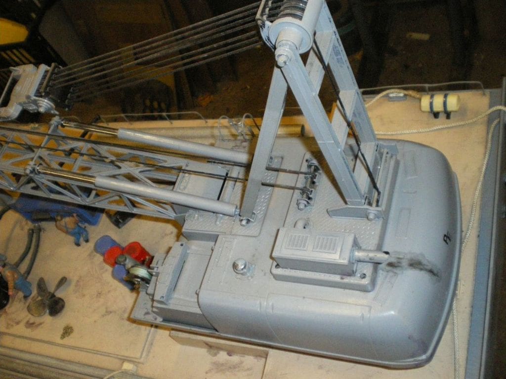
I had drawn up a list of some of the things that I thought could be accommodated in this project. Starting off with the all important large flat deck, a big winch, a pump or generator and the very large crane were of course essential. I had built a working crane before which was installed on my dredger. This worked well but had been a lot of work due mainly to its small size, but this time I was lucky that before I actually started building this much larger crane, I came across a model of a large radio controlled tracked crane at a model engineering show. I thought it was cheap as it had also been reduced in price, so I bought it. I considered that if I was just able to use the radio gear and winches then I was saving myself a lot of time and expense. However all the under parts had to be cut away just to remove the tracks and that involved cutting a lot of the crane structure as well. I finished up after a lot of cutting and shaping with a flat underside to the main body which could be attached to the deck on a completely new under frame.
The plastic cab and some of the other ancillary bits were removed and the many holes that I had created were made good with either plastic card or fibreglass, Photo 1. I think on later reflection it might have been easier to scrap the original crane body and make a completely new one, but hindsight is a wonderful thing!
The hull
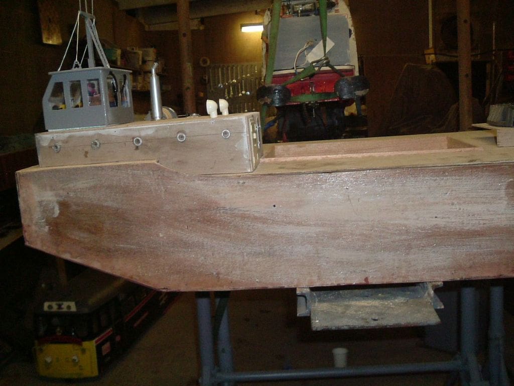
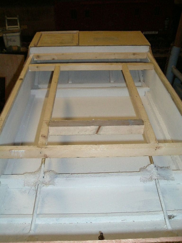
This is of a very simple plywood construction with square ends, Photo 2. It was in fact a copy of a barge I had found on the internet. I wanted my barge to be as large as possible, but I needed to be able to pick it up when completed and it also had to fit in the car as well! The final hull size was really determined by what could be cut from an 8ft x 4ft sheet of 3mm plywood that I had in stock. Scrap cardboard was used to get the rough sizes of the sections which were carefully marked on to the ply. With care, it was possible to cut the sides, base, ends, bottom and deck from the one sheet. The hull was strengthened by having an internal frame of 3/4in square section wood pinned and glued to the ply to give it extra rigidity, Photo 3. There also had to be extra supports under the rear deck for the crane mounting. Once the basic hull was made, but before the top deck was fastened in place, the propshafts and the water intake pipe for the pump had to be installed before the whole of the inside was painted and sealed with fibreglass resin. The corners of the hull (inside and out) and the internal frame joints were reinforced with woven mat and plenty of resin. This was just to make sure it was strong and watertight. Weight is not a problem with this type of hull, just your ability to lift it! The inside was then painted with two coats of undercoat and the outside had the same but a top coat as well.
Ballast
I was intending to use large internal water tanks to ballast the hull. These would be filled and emptied using a windscreen washer pump, the fixed inlet pipe of which would have to come up over the water line because if the flexible hose connection were low down and came off or leaked, I could witness a sinking that would not be desirable! With the pipe directed up to deck level no water should come in at all if anything like that should occur.
However, the idea of having tanks filled with water by a pump was soon altered when I sought some advice from Derek Nelson of Knightcote MBC who advised against this method. I could see the sense in what he told me, so I now use old plastic milk bottles filled with pond water. This method is easy and makes ballast positioning spot on. If you have a selection of large and small bottles, then once the trim is correct, if they are then numbered with a felt tip pen both on the bottle and in the hull, filling at the pondside and then positioning them becomes easy for future sailings.
Motors and rudder
At this stage before the decks were installed, I decided to utilise the motors that had driven the original crane tracks. These, although quite small would hopefully be adequate to drive the two small propellers. On this type of vessel, high speed is not a requirement, so I hope they will do the job. Motor control is independent on the transmitter, but also of course the barge in real life would be more likely to be towed into position.
The rudder is just a large fin in the centre at the rear. Normally this would be set straight and I should imagine that with the barge ballasted and low in the water a lot of power may be required to move it. It will be interesting to see at a later date how it works out. The best of it is that if larger motors are required later, the cavernous hull should make them easy to fit.
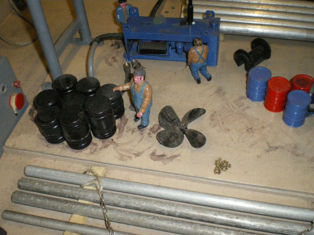
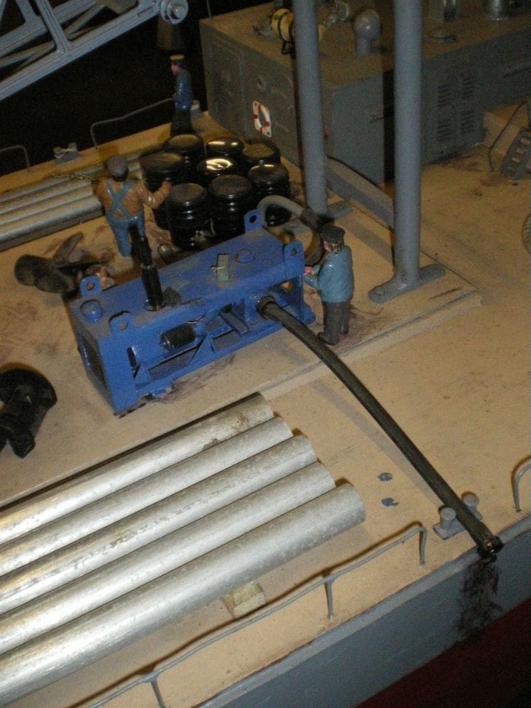
Deck fittings and clutter
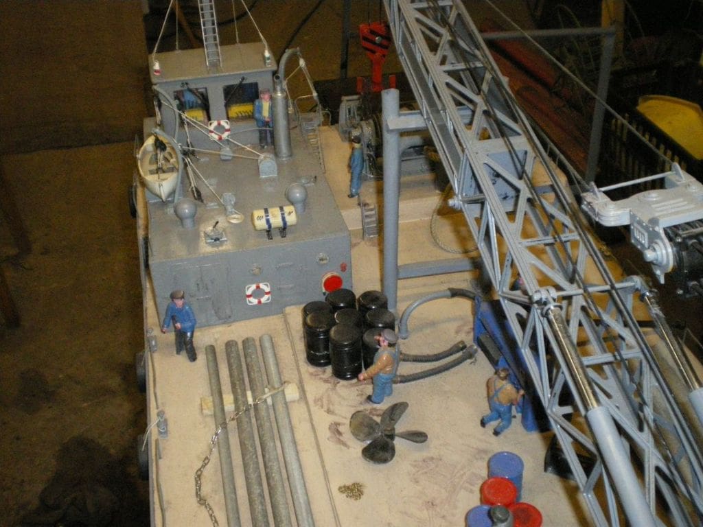
If you look at photos of working examples, barges do not seem to be tidy craft and there is often a lot of clutter on the deck. By that I mean ropes, drums, chains, pipes and timber etc all over the place, Photo 4. On the deck are winches and pumps with anchor handling equipment at both ends of the barge with a main towing bridle at the bows (although both ends of the hull are similar in shape). The crane of course is the main feature and is mounted aft. On each side of the deck are bollards and plenty of tyre fenders plus the usual guard rails. At the opposite end of the deck to the crane mounting is a large heavy tubular structure for supporting the crane jib when stowed, Photo 5.
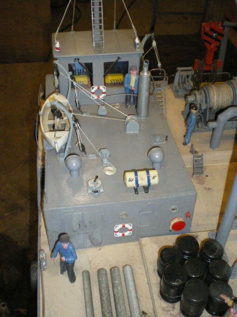
At the bow end of the barge on the port side is the crew accommodation block and engine room, on top of which is housed the small bridge with the crane controls. Aft of the bridge are stowed the lifeboat and a liferaft, Photo 6. On top of the bridge is a small mast for the radar, aerials and navigation lights.
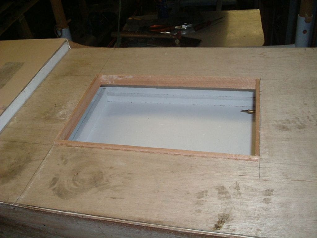
Access
In the centre of the barge deck is a large hatch, to enable access into the hull to get the ballast in and out and to the batteries and motors etc., Photo 7. On the top of this hatch some the deck cargo is glued in place and a large engine driven pump unit. Water for the 12v windscreen washer pump comes via the inlet pipe in the hull. The pump outlet pipe then goes through the hatch cover and into the dummy pump unit on deck, Water exits from this pump through the hose which is laid on the deck, just discharging over the side, Photo 8. There is a separate hidden electrical switch for this unit, as it is not required to run continually.
Other fittings
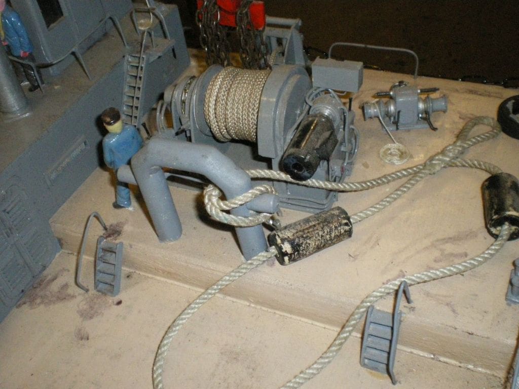
Most of these I either made or had in stock left from other projects. To me this is the fun of the thing, making all the little bits and pieces that make up these models. I have always collected photographs of any boat fittings or indeed anything interesting which I then keep on file. Then once a new project is commenced, they can be reviewed to produce ideas and possible solutions to any problems with that model. Winches are a good example and you can never have enough pictures.
The winch for this barge, Photo 9, was actually a copy of the one on the ferry from Ardrossan to the Outer Hebrides and was photographed in 2007. This was used to pull the ferry into position for unloading and as I was standing directly above it when it was being operated, I had ample opportunity to take plenty of pictures. These were used to create this model version, together with other pictures for the anchor winch from the same vessel. To me, models do not have to always be 100% accurate, but they do have to look right, certainly on first impression.
Many of the deck fittings were made before the basic hull was completed to provide some model making diversity. The large fairlead that takes the main winch rope with the anchor chain handling at the side of it is an example of this. It was made from bits from the scrap bin with a bit of machining where necessary. Then came the aforementioned winch followed by many of the smaller fittings including the davits and lifeboat etc.
Painting and power supply
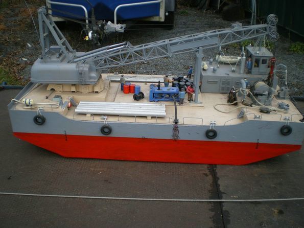
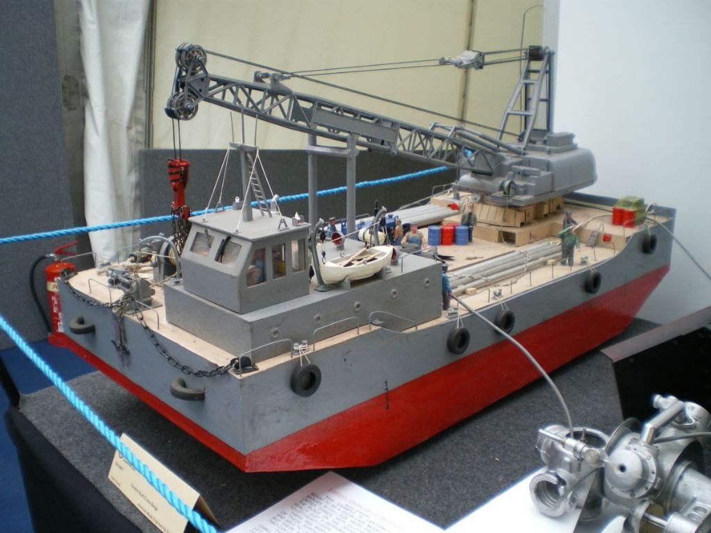
There is no fancy paint work on this model as it is intended to be a working model and not a museum piece. The hull is red below the waterline and grey above. In fact the whole thing is meant to look pretty scruffy just like the full size barges. Two 6v batteries power the lights, pumps and motors. I have yet to find out how long they will last, but this will probably all depend on how much use the crane gets. Photo 10 is of the model on display at the Midlands Model Engineering Exhibition, 2009.
Conclusion
It was fun to make the crane barge, as I used whatever I could find at the time that could be modified, an example of which are the barrels on the deck, which are the screw tops from bottles fastened together with resin. Why did I start this project? Well, first I wanted a barge to tow behind my tug and it graduated into what you see now, plus second I wanted something different. Last, but not least, I wanted the challenge of scratch building rather than kit bashing. In the end, I am happy as it has been interesting to build with a minimal capital outlay which as far as I am concerned ticks all the right boxes.
(Peter who also makes 7 1/4 inch gauge trains is obviously very innovative and as he said in his letter to me, boats make a change from trains. This model is still ‘in progress’ at the time of writing. I particularly like the idea of using the working crane from the r/c ‘ready to dig’ earth moving models that can now be purchased very cheaply. Knightcote MBC operate in Warwickshire and Derek Nelson is their secretary, tel: 01926 640045 Their club water is situated in the village of Knightcote which is a few miles off J12 on the M40 – Editor)


