H.M.S. VANGUARD
KEITH JULIER reviews the latest Victory Models kit
Enjoy more Model Boats Magazine reading.
Click here to subscribe & save.
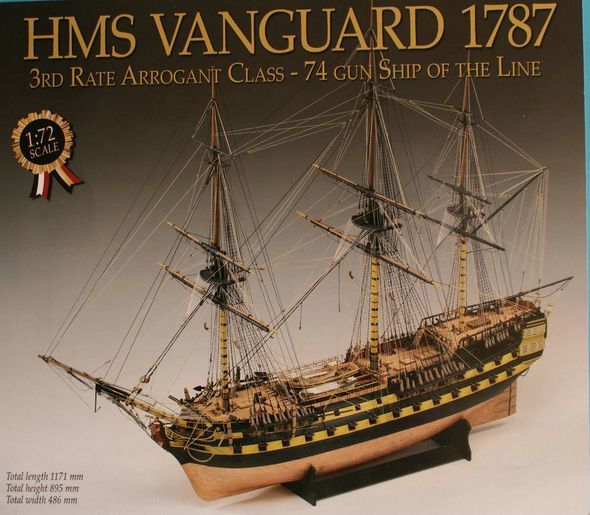
H.M.S. Vanguard, as kitted by Victory Models, is for a model of the fifth naval vessel to bear that name and one of fourteen third-rate, 74 gun ships forming the Arrogant class.
Designed by Thomas Slade and launched in 1787, Vanguard is probably best remembered for being Nelson’s flagship at the battle of the Nile, in Aboukir Bay in 1798. Like most 74’s, the workhorses of the fleet, she had a very full and active life including service in the Baltic and the West Indies, before being broken up in 1821.
As designed, she carried twenty eight short 32pdrs on the lower gun deck, twenty eight long 18pdrs on the upper gun deck and eighteen long 9pdrs on the forecastle and quarterdeck, so could deliver quite a formidable broadside.
It is interesting to note just how much timber went into the construction of a 74 gun ship. Over 3000 loads of timber were required, the majority being oak, required the clearing of some 75 acres of forest land.
The kit has been designed in order that the model maker can choose to make Vanguard, Bellerophon or Elephant, all Arrogant class vessels. All design differences are clearly indicated in the instructions and on the drawings, and all alternative and necessary parts are included in the kit.
As a further point of historical interest, I found that all three vessels were engaged together in forming part of Commodore John Loring’s squadron cruising off San Domingo blockading French ships in the harbour of Cap Françoise in 1803. There may have been other instances of mutual activity but this is the only one I have found so far.
The kit
This came in a big box and a heavy one too, perhaps not so surprising when you consider the size of the finished model. You are going to need space for a model with an overall length of 1171mm, height of 895mm and width of 486mm, so definitely not one for the mantelpiece.
One of the innovative features of the kit is the use of MDF for the basic structure of the hull, bulkheads, false keel etc. I found the material more than fit for purpose and in many ways superior to ply. It came flat and stayed flat, ideal for those models like Vanguard where the false keel is in two parts. With sharp tools I found that the chamfering of the bulkhead edges prior to planking was easier and quicker than with 5mm ply.
The general standard of timber was good, much of the sheet material being solid walnut and the laser cutting providing all the pre-shaped parts necessary with minimal tabbing to cut through to release parts from their host sheets. Strip wood was well edged and straight, likewise the dowels provided for the masts and spars.
The etched brass sheets were as good as any I have seen in a period ship kit, providing masses of fine detail such as deadeye strops, chain plate links, gun port hinges and scuttles. The decorative castings were crisp and clean and highly detailed.
Twelve different sizes of rigging thread together with associated blocks and fittings gave some idea of the task ahead.
A 31 page assembly booklet and an instruction manual supported twenty sheets of well drafted drawings and a parts list, all text being created in English, (as against an English translation from Italian).
Tools required
The tooling requirements for building this kit are not very extensive due to the vast amount of precut items provided. However, because of the size of the finished model, an above average amount of paint and other consumables are needed.
Craft knife preferably with renewable blades.
A selection of needle files.
Razor saw.
Small wood plane or David plane.
Pin vice or small electric drill.
Drill bits 0.5mm to 3.0mm diameter.
Pliers/wire cutters.
Tweezers.
Various grades of abrasive paper and sanding block.
Selection of paint brushes.
Dividers.
Steel rule (12in or 300mm).
Small clamps or crocodile clips.
Pencil (H or HB grade).
Masking tape (Tamiya 6mm is recommended).
Small hammer or pin pusher.
Plank nipper (Amati Art.7381 is recommended).
Plank cutter (Amati Art.7386 is recommended).
White PVA adhesive.
Cyanoacrylate (superglue) medium and thick grades.
Epoxy resin adhesive.
Walnut wood dye.
Walnut or dark wood filler.
Indian ink.
White spirit.
Matt polyurethane varnish.
Black paint (Humbrol 85) – 3 tins.
White paint (Humbrol 34) – 1 tin.
Blue paint (Humbrol 25) – 1 tin.
Yellow paint (Humbrol 74 Linen) – 3 tins.
Red paint (Humbrol 60 mixed with 25% Humbrol 70) – 3 tins and 1 tin.
Copper paint (Humbrol 12) – 1 tin.
Gold paint (Humbrol 16) – 1 tin.
Flesh paint (Humbrol 61) – 1 tin.
Leather paint (Humbrol 62) – 1 tin.
Etching primer Black recommended – 1 tin.
Humbrol Clearfix For fixing acetate windows.
I would remind everyone that the dust from MDF is not very pleasant and that a mask should be used when using abrasive papers, although sharp tools work so well, dust from sanding can be kept to a minimum. Similarly, extended exposure to cyanoacrylate requires the use of a respirator for ideal protection, particularly during the coppering process.
Making a start
Before commencing the actual construction, there were several things that could be done to advantage, not least of which was to study the drawings and read the instruction manuals. This kit is a fairly complex project and considerable time was spent in the preparation of the manuals to keep the construction as straightforward as possible. They are not there for use only if you run into difficulty, but rather to prevent you getting into trouble in the first place, the prime problem usually being sequence of assembly. Manuals and drawings should be used in conjunction with each other and not in isolation
Having sorted out the basic building procedures, the next stage was to identify the pre-cut parts before removing them from their host sheet. Marking them with their relevant part number using a soft pencil is ideal.
How many times have you got annoyed when later in the construction, you need to assemble half a dozen copper eyelets and realise that they need to be painted black first? There are about five hundred of the things in this kit so I decided to prepare a couple of hundred at this early stage. I keep a piece of scrap timber specifically for the job. Basically it is drilled with two hundred holes each 0.7mm diameter and deep enough to house the entire shank of the eyelet. Having loaded all the holes with eyelets, I then painted the eyes with etching primer prior to applying a coat of black paint. These were then put to one side to dry ready for later use. When removed from the wood strip, the shank will have remained clean and free of paint, thus avoiding the need to scrape before applying adhesive. A second and third batch would be conveniently done during waiting times for paint and glue to dry at various stages throughout the construction.
In a similar manner, the etched brass sheets were primed and painted en-masse at this stage, noting whether parts required painting on one or both sides. The usual touching in after assembly would obviously be required.
Basic hull construction
Having read through the instruction manual several times, I noted that later on when planking, the first planking terminated at the bearding line and only the second planking extended to the 5mm thick stern post. Unless something is done to reduce the 5mm thickness of the false keel in that area, the 1mm second planking will require reducing to almost nothing at the front edge of the sternpost, not a desirable task. Accordingly, I used the bottom forward corners of last few bulkheads dry fitted in position to determine the bearding line and from that line tapered the false keel to about 3.5mm thick along the edge onto which the sternpost would subsequently be fixed, Photo 1. Thus, there would be only 0.25mm to remove from each side of the second planking in order to match the thickness of the sternpost. This procedure was carried out on the bench prior to any permanent assembly of bulkheads to the false keel.
The second aspect that you may need to consider is what sort of stand you are going to use to exhibit the finished model. The kit provides pre-cut parts for a supporting cradle, but if you wish to use a base and pedestals, then any work required on the false keel is best done before assembling the bulkheads. I personally favour the pedestal method and thus introduced two 1.5in (40mm) lengths of 5/32in brass tube in the bottom edge of the false keel. These house 1/8in diameter brass rods that pass through the pedestals into a wooden base. The rear housing can also be seen in Photo 1.
The main skeletal framework of the hull comprised the false keel and bulkheads, all locked together by the lower deck pattern, Photo 2. The accuracy of the pre-cutting was such as to provide just the right fit for easy assembly without any adjustment of slot width or depth. Having made a dry run I then took everything apart and taking the first four and last four bulkheads, rough bevelled their edges to conform to the curves at bow and stern, Photos 3 and 4. Assessing just how much bevelling to do at the front end can be helped by the use of the upper gun deck, the upper deck patterns and the upper gun deck front platform to eyeball the curves at their particular level. A planking strip was used to gauge the more severe degree of bevelling at the stern. Once I had reached the ‘near enough’ stage, all the bulkheads (except the last) plus the two parts of the lower gun deck pattern were glued in place and the assembly put aside to thoroughly cure. It was imperative to ensure that the bulkheads were properly square to the false keel to avoid later problems when fitting the gunport patterns. The lower dummy barrel strips were slotted into position and the last bulkhead with the stern counter patterns was then put in place.
It was easier to finish off the bevelling of the bulkhead edges before fitting the stem, keel parts and rudderpost. The bevels at the lower end of each relevant bulkhead were then used to determine the shapes on the edges of the plank termination patterns. These shapes were then produced on the bench before gluing the patterns in position.
The stem and keel parts were then permanently assembled and the semi-circular front deck assembled and planked.
The front bulkhead sub-assembly was constructed and painted, again before fitting. Two important points to remember here; make sure that when constructing the round-houses, the three patterns are in exact vertical alignment and second, when placing the sub-assembly on to the front face of the first bulkhead, it is centrally disposed, Photo 5.
The upper gun deck
The false deck came in two parts, each of which required to be cut long the centre line for ease of assembly. Again the accuracy of the laser cutting came to the fore and only a minimum of adjustment to slot depths was required to attain a snug fit of the deck parts to the bulkheads. It was important that this fitting adjustment be done to the slot depths and not the centre line edges, otherwise you get oval holes for the masts and capstans and undersize hatch openings.
The manual suggests that the false decks may be planked before assembly. Certainly it would make it easier to sand the planking, but it would leave the dovetail joint connecting the fore and aft parts exposed to view, Photo 6. This joint is almost hidden from the casual viewer by the deck above, but if you are building for competition or exhibition, remember that some judges carry inspection mirrors!
The next decision to be made concerned the method of planking; planking strips that ran in one length fore and aft, or planks cut to individual lengths and laid to the correct pattern? Again, for the exhibition model, the latter choice is probably better and I would suggest that a length of 127mm (5.0in) to represent planks 30ft long laid to a 4-butt shift system would be acceptable. This pattern of planking would apply outside the width of the apertures for gratings and hatch coamings. The essential thing here was to ensure that all planks were cut to an identical length and I did this by clamping my plank cutter to the bench alongside a stop block set five inches from the blade edge, Photo 7. Once laid, the deck was given a coat of matt varnish.
The next step was to line the inside of the bulwarks. One of the anticipated problems associated with the inner lining was the breakout of the inside surface when cutting the gun-ports. The manual suggested that after assembly, they be brushed with dilute PVA adhesive to minimise this problem. In fact, I took the six strips required and brushed them on both sides, let the adhesive dry, sanded them, then painted them red on one side before cutting and fixing in place. This avoided the hazard of getting adhesive on the newly laid deck and also prevented red paint getting on the deck as well. I used a crocodile clip or clamp on every bulkhead to maintain a good inner surface when gluing the planks in position.
The upper gun-deck fittings comprised the ship’s stove, Photo 8, gratings and two capstans. All of these items were easy to make, but there are a couple of points worthy of mention.
The position of the stove was best assessed by using the upper deck as a guide, remembering that the chimney should not be attached to the stove until much later in the build.
I found that the capstans were best built on the end of longer piece of dowel than the 22mm quoted in the instructions and cut off to leave the required spigot length (1mm) after assembly.
There is a golden rule for gratings – get them the right way round! The ledges go athwartships and the battens, which can be seen in their entirety from above, go fore and aft.
The grating strips were dry assembled to approximately the size required and brushed with dilute PVA. The newly brushed gratings were dabbed with an absorbent cloth to avoid an accumulation of adhesive in the grating apertures then set aside to dry. The edges were then trimmed to finished size and sanded square. The coamings were then built up around the grating, assembling the athwartships pieces first followed by the fore and aft sides. All gratings for the entire model were made as a mini project, Photo 9.
Once all of the fittings were in place, the beams to support the upper deck were glued in position and painted red, Photo 10. The upper deck was then temporarily dry fitted and its edges sanded as necessary to follow the external lines of the hull. The stern gallery platform was also planked and fitted at this time.
The gun port patterns
Backtracking a little, before attempting to put the gun port patterns in place, a word about the lower deck twenty eight gun ports is in order. These ultimately have to be lined and the only surfaces to which the lining pieces can be attached are the 1mm thickness of the patterns themselves and this is not an enviable task. This is because these particular ports have to have their linings recessed back 1mm to accept a closed port lid. There were two alternatives; frame the apertures on the inner faces of the patterns with say 2mm square strip to increase the contact width to 3mm or as I did, make up lengths of box section so that the linings could be slid in place. Both methods require considerable care and patience. Obviously, if the framing option is selected, then this has to be done now before assembling the patterns to the hull framework, noting that some of the apertures are adjacent to the bulkheads where a frame member cannot be placed. The option involving the box section is discussed later.
The patterns were soaked for an hour to make the 1mm ply sufficiently pliable to conform to the curves of the tumblehome. These were initially fitted by pinning and with clips to ensure that their position was correct before committing to glue. The top edge of the upper patterns aligned with the top of the bulkheads, the fore and aft position had to be judged carefully so as not to have any interference of bulkheads into gun port apertures, hence my earlier comment about getting the framework square and true. It was particularly important to ensure that the slots for the subsequent fitting of the quarter galleries were at the same level, port and starboard.
The upper patterns were positioned first, using both pins and clamps and/or clips to hold the ply tightly against the curves of the bulkheads. It was found advisable to let the upper patterns dry out completely before proceeding with the fitting of the lower parts. Some minor adjustment and pre-bending at the bows of the front part was found helpful before final fitting, Photos 10 and 11.
A further problem was encountered as the upper patterns dried out. Due to the constantly changing cross-section of the ply where the pre-cut gun port apertures were positioned, the top edge of the patterns tended to undulate between the bulkheads. This was easily overcome by introducing some spacers into the cavity wall between the inner bulwark planking and the inside of the patterns; short lengths of scrap 5mm wide strip fitted the bill nicely.
First planking
The timber provided in the kit for the first planking was ideal for the job. It was both pliant and easy to cut, albeit that some pre-soaking at their ends helped. Another procedure worthy of consideration was to make each plank in two lengths, staggering the butt joints over four bulkheads similar to a four-butt shift system used for deck planking. This process had two very distinct advantages; all joints could be glued and pinned before the glue started to go off and, by having shorter planks, both the fore and the aft ends could be soaked at the same time, (commandeering the bath for soaking long planks does not always make for domestic bliss).
Planking started at the bottom edge of the gun-port patterns and worked down to the keel, Photo11. This was a relatively straightforward task, although due to the size of the hull, it was a fairly long job in spite of the 7mm width of the planks. Inevitably, some stealers were required in order that planks were permitted to take their natural run down the length of the hull.
It should not be forgotten that the pattern of the first planking is relatively unimportant, its main purpose being to provide a sound base for the second visible planking
Having got all of the planks in place and having let the glue thoroughly cure, all pins were removed preparatory to rubbing down. I find that the half-round Permagrit abrasive tools are ideal for the initial rub-down and quickly remove any high spots on the planking before finishing off with decreasing grades of abrasive paper.
The fitting of the stern counter fascia was done by soaking and scoring to attain the required curvature. Due to the adverse direction of grain, soaking alone was inadequate and a series of light cuts about 3mm apart were applied to the inner face of the part to assist bending before gluing and pinning in place.
Gun ports (one)
Using the pre-cut apertures in the gun port patterns as a guide, a series of closely centred holes were drilled through the inner wall of the upper gun deck and a scalpel used to remove the centre portion. The resulting aperture was then trimmed to size ensuring that the top of the aperture in the inner wall was level with that in the outer wall. It would be better to err slightly on the high side so that the top of the gun barrel doesn’t foul on the underside of the top surface of the lined gun port.
The first and only gun ports to be framed at this stage were the ten ports without lids, the framing to be made flush with both the inner and outer hull surfaces. The recommended framing material, comprising two strips of 6 x 1mm glued edge to edge, was then used to line the ports. I found that if the grain of the lining runs vertically on the sided and fore and aft on the sills, the visible edges turn out in a much neater fashion than would be the case with the cross-grain exposed.
The ports on these vessels were set between frames with horizontal upper and lower sills. Thus, to be strictly accurate the vertical sides on the model should be positioned first with the horizontal sills set between.
Main wale position
Drawing sheet No.1 was used to establish the position of the main wale. Dimensions were taken vertically down from the sills of the lower gun-ports to the top edge of the wale and transferred to the planked hull. A planking strip was pinned in this position and a line drawn down the length of the hull on one side. The other side was treated in a similar way, but taking into account any small adjustments to ensure symmetry between the sides.
Quarter galleries
There was some information missing for this stage of the build, nothing terrible, but it needed sorting nonetheless. Referring to the 5mm MDF sheet numbered 2418, it was found that there were four unnumbered pieces obviously associated with the quarter galleries. These were Part Nos. 27 and 28 (two of each) and were the top and bottom patterns for the assembly and would require shaping to match castings later on. They were not shown in the construction manual – DO NOT DISCARD THEM.
Similarly, Part No.160: The quarter gallery lower panel patterns, were not shown; these were similar to the upper panels No.46.
It was essential to use the stern fascia as a guide to setting up the parts for the quarter galleries and this part was temporarily, but firmly, pinned into place. Although the construction of these assemblies was not difficult, it did demand a lot of care and patience to get everything right. The angles of the patterns Parts 58 to 63 relative to the hull are critical to a successful build and the edges of these parts were chamfered accordingly to provide maximum gluing area.
The window frame panels were only temporarily fitted at this stage to be removed later for glazing, Photo 12. A modification to Part No. 162 (Quarter Gallery low window pattern) was found necessary. The wider side frame should be at the stern end of the row of windows and not the foremost end. The front-end width was therefore reduced and a scrap piece of similar width added to the rear edge.
Second planking
The instruction manual suggests that the first plank be laid on the line of the main wale previously marked adding planks above and below that line until the entire side had been planked.
The planks were applied using either thick or medium grade cyanoacrylate thus avoiding the use of pins. When planking models of this length, I have found that apart from the first plank, there are distinct advantages in laying the planks in two or three separate lengths using staggered butt joints. Gluing is easier and positional control of the strip is more positive. A further aspect well worth remembering is if the planks are soaked to assist bending, the adhesive grabs at an enhanced rate.
Above the line of the main wale, the planking has to contend with the gunport positions and it is important not to cover these over, but leave enough of the aperture open into which a scalpel can be inserted for later trimming. In fact, I trimmed each aperture almost to finished size as I proceeded.
Planks required tapering, particularly below wale level at the bows and stealers were needed at the sternpost end to keep a natural run on the planks. It was imperative that all planks sat tightly down on to the surface of the first planking in order to create a sound base for the coppering of the area below the waterline and a blemish-free surface for painting above the waterline.
The window frames for the quarter galleries were temporarily left in place while planking the adjacent areas, then removed for later glazing, Photo 13.
Inevitably, I found that after rubbing down, some minor gaps needed the application of filler prior to finish sanding. This was quite a large area to sand and thus created a lot of dust, so a facemask was most definitely needed.
Inspection of the drawings showed that the wales overlapped some of the gun-ports, so it was decided to leave the final trimming and lining of the ports until after the wales had been fitted.
The wales
Having already established the position of the top of the main wale earlier, the first of the wale planks was laid accordingly using cyanoacrylate. There were a number of things to take into account here, not the least of which were the soaked planks. They needed to be well saturated in order that they would be pliant enough to coerce around the curves of the hull and lay flat on the surface. The problem was, of course, manhandling the damp planks into position while resisting the almost instant grab of the adhesive. To ease the situation as much as possible, I used thick grade superglue and applied it to the hull rather than the plank.
The upper wales and strakes were then added using cardboard spacers the maintain parallelism between them and the main wale.
There were places where the natural run of the wales and strakes took them across the gunport apertures. These were now cleared away and the gunports trimmed to size.
Gunports (2)
The lidded gunports were framed using 12mm wide strips as before, but leaving a 1mm deep recess around each aperture. This was relatively straightforward for the gunports on the upper gun deck where the frames were supported by both the inner and outer walls of the hull. However, fitting frames to the lower gun deck ports was not going to be so easy where the only support was the 1mm thickness of the gunport patterns. I therefore chose to adopt an alternative procedure.
The recommended 12mm wide framing strips were used to make up a couple of 250mm lengths of rectangular box section for framing the twenty eight lower gun ports. Accurate measurement of the pre-cut apertures revealed that the 12mm required a very slight reduction on two sides before making up the section, which needed to be a gentle push fit into the apertures. Superglue was used to construct the box sections and when thoroughly cured, the assembly was given a good soak in dilute PVA for final strength to help avoid collapse when sawing off the lining sections.
To fit the frames, the end of the section was introduced horizontally into the gunport aperture to the depth required, Photo 14, and the angle of the tumblehome marked on the sides. The top surface was also marked to identify which way round the lining fitted. I chose to make each lining approximately 12mm deep so as to retain some stability and strength for the forthcoming saw cutting. The section was then removed and the piece sawn off at the pencil mark using a sharp, fine razor saw and not too much ‘oomph’! Each side was cut separately to minimise stressing the part while sawing and the saw taken ‘not quite through’ the material, final separation being made with a scalpel. The exposed end grain was sanded smooth and the piece coated with PVA adhesive and re-introduced into the gunport aperture to form the 1mm deep recess to house a closed gunport lid.
This process worked well and is one that I would adopt again. For the record, I spoilt only three linings, all due to failure of some part of the glued joints when making up the lengths of box section, coupled with me pushing too hard on the saw.
The linings were then all painted red ochre although obviously those associated with the top deck were left until a later stage.
Upper gun deck
Adding the shot garlands at the sides of the hatch coamings and putting ladders in position between decks completed the fitting out at this stage.
The instruction manual offers the option of fitting the gun carriages at this stage prior to fixing the deck above, adding the barrels from the outside after painting. I discovered that this could not be done; the barrel trunnions would not pass over the tops of the carriage sides! Therefore, the deck above should NOT be fitted until after the hull painting has been carried out. This is the designer’s preferred procedure.
Coppering
On plated hulls, I usually adopt the practice of running a length of 0.5mm x 1.5mm wood or plastic strip along the waterline. This not only provides a positive edge up to which the plating can be laid, but also simulates the 3 x 1 inch batten that was normally applied to the top edge of the plating. This strip was painted black before commencing the plating operation.
The actual plating required a lot of patience. The instruction manual described the procedure quite adequately but I would add a few points that should be of help.
Starting at the keel may not be the easiest place if you haven’t coppered a hull previously. The transition from straight lines of plates to the continuous curves of the upper parts of the hull via stealers is not always easily assessed. I chose to start midway between keel and waterline using a wooden planking strip that started and finished at the extreme ends of the waterline. On my model, this was the twelfth row of plates down from the waterline, Photo 15. With this wooden strip lying naturally flat down on the surface of the hull, I drew a pencil line to guide the first run of copper plates. This established the natural curve and it was then a matter of plating both above and below that line. The stem, keel, rudder and sternpost were all plated horizontally as separate entities.
It was soon found that the copper plates, snapped off from the sheet in rows of seven pieces, were best applied singly or in joined pairs, although there was at first a great temptation to save time and apply them in strips of three or more. However, the curves involved were such as to frequently prevent even two joined plates ‘holding the line’.
Where the plating intersected the waterline, stem and sternpost, there were several very small pieces of plate required. It was helpful to keep these integral with the adjacent plate for convenience of handling.
The rudder was also plated at this stage, its unplated edges painted with copper paint along with the edges of the keel, stem and sternpost.
The plates were stuck on using thick grade superglue and yes, I did remember that extended exposure to the stuff requires the use of a suitable facemask.
The ‘Nelson Fashion’ paint job
By usual standards, it seemed a bit early in the project to think about painting. However, the essential masking had to be done before mounting the guns and they had to be positioned before adding the upper decks, so now was the time to get the paint pots out.
The masking was a tricky job due to the fact that the bands of yellow ochre followed the line of gun ports rather than the rails and wales. Frequent eyeballing where paint and wales coincided was necessary to get a true continuous line.
I did not take the black paint up to the gun-ports on the poop deck at this time since some further woodwork looked possible after the upper decks had been added.
Three coats of yellow ochre and two of black were found necessary to provide an acceptable finish, Photo16.
The upper gun deck
Once the outer paintwork had thoroughly dried, the remaining fittings for the upper gun deck were put in place. The previously assembled capstans were fitted together with the bitts at the main mast area. The ship’s stove was a mini project that produced a unit as good as any I have seen. It seemed such a pity that there was little to see of it after the model had been completed.
The large wooden cleats for belaying the sheets to the lower courses required pinning as well as gluing to the inside of the bulwarks. If they were to come off during the rigging process, it would be almost impossible to re-fix them.
The guns and carriages were glued in position using an epoxy two-part adhesive, again for added security. A useful tip is to draw the carriage wheels across a sheet of abrasive paper to produce four small flats; the increased area of contact makes for a much stronger joint.
Rigging the guns needed to be done at this stage, prior to putting on the main deck above. At this scale the only rigging I applied was the breeching rope from eyelets on the inside of the bulwarks to the cascables on the rear of the barrels. Anything more than that would have been quite a formidable task bearing in mind that the carriages are cast metal rather than wooden and wood require fitting out with eyelets. This stage of assembly can also be seen in Photo 16.
The top deck
Once the upper gun deck had been fitted out, the top deck was put in place, Photo 17. Because of the dovetail arrangement for joining the fore and aft parts of the false deck, planking had to be done in-situ after fitting the glazed screen bulkhead. This stage of the build introduces window glazing that had to be applied to the upper stern gallery and the screen bulkheads, Photo 18. The method suggested by the designer worked well. One subtle variation that would be useful to the modeller who did not have a fine Edding pen to mark the clear acetate sheet, would be to use a scriber or heavy duty needle.
The advice concerning the non-use of superglue as adhesive for sticking the glazing pieces in place is sound – don’t use it! Humbrol Clearfix was found to be as good as anything I had thus far come across, but epoxy glue is also fine albeit a bit messy.
Having fitted the glazed parts in position, the deck was planked and the inner bulwark surfaces lined. The gunports were trimmed to size and eyebolts put in place to anchor the breeching ropes before finally fitting the top deck.
The stern fascia
Sadly I ran into a problem at this juncture in that the taffrail casting (Part No. 444) was undersize relative to the ply stern fascia (Part No. 117). I understand that the problem has now been put to rights and that correct castings are available from the distributor. However, I continue with my notes in the hope that my corrective procedure may be useful for those modellers who purchased very early production kits.
Essentially, I cut the casting into three parts, making the cuts just behind the figures sitting above the inner stern pillars. The parts were ultimately positioned on the ply fascia with gaps of about 2.5mm, filled in with scrap timber and filler, Photo 19.
Before permanently fitting them in place, the windows in the fascia should be framed and glazed. The second problem that arose was that the rigidity of the casting made it virtually impossible to bend the metal to conform to the required curve of the stern fascia. The fact that the casting was now in three parts helped solve the problem but an essential sequence of working had to be adopted which as it happened had several distinct advantages.
In order to put the bend into the framed and glazed fascia, I glued four small clamping blocks (two each side) on the horizontal surfaces of the quarter galleries, Photo 20. These enabled the fascia to be clamped in place with the correct bend while the three parts of the casting were glued in place with epoxy resin, Photo 21. This temporary assembly was left overnight to cure before releasing the clamps. The fascia, having been removed from the back of the model now had the correct bend in it and was more readily accessible to do the filling and final decoration on the bench. When this decorative work was complete, the finished assembly was permanently glued to the stern of the model, again using the temporary clamping blocks. Once the adhesive had properly cured, the clamping blocks were removed prior to finish building and decorating the quarter galleries.
The poop deck
Before permanently fitting the deck in place, it was necessary to study the upper deck area and ensure that all deck fittings had been put in place, eyelets, binnacle, ship’s wheel etc, Photo 22. Access becomes very limited once the poop deck is fitted, Photo 23. The knees, mizzen bitts and skylight assembly were then added.
Capping rails, poop railings and barricades
I have grouped these features together as they all share the same constructional comments. Building them all together as a mini-project had advantages, but was not essential.
Forecastle capping rails were all painted before assembly to avoid fiddly brushwork as were timberheads after their assembly to the lower rails.
The ‘midships capping rails were also painted before fitting and they were also drilled and fitted with the required pin racks. Drilling centrally into the edge of the capping would be extremely hazardous after assembly.
The poop deck railings should be painted as assembly proceeds and, again it is advisable to fit the pin racks to the inside of the top rails before assembly.
Thick grade cyano was used throughout the railings construction. For reasons of vulnerability, the hammock cranes were not fitted at this juncture, but left until the final stages of hull assembly.
The head rail assembly
Frequently one of the more problematic areas of the build of this type of vessel seems to have been solved in this kit. That is not to say that it was a ‘throw together’ task, merely assembling pre-cut parts, but patience and care was readily rewarded with a good looking job. The secret was adequate preparation and sequence of working, the former being the work on the slots of the three Vee shaped bow rail frames; having got them at the right angle and depth, the fitting of the bent cast rails became relatively simple. Painting the parts before final assembly was also essential for a neat looking job.
There was a lot of eyeballing and dry fitting to do and my neck muscles needed a massage afterwards, but patience paid off, please see Photo 24.
Gunport lids
Study of the drawings and instruction manual quickly indicated that this part of the project was not going to be merely a couple of evening’s work. The realisation that there were eleven elements in each of the lower port lids, (including the tackle), and the two-colour paint job, pointed to the enormity of the task ahead. The basic structure was attained by laminating strips of walnut with a ply base of sufficient length to accommodate each size of port lid. Each lid was then separately cropped off ready for fitting out with hinges, scuttles and eyelets. These sub-assemblies were painted red on their undersides and edges before mounting on to the hull sides.
Hole positions were carefully marked on to the hull and drilled to accept the hinge projections, which were glued in place with superglue. Once the glue had cured, the upper surfaces of the lids were painted black.
It was seen as advisable to rig the port tackle at this stage, before attempting to fit the channels, since the space below those channels that sat immediately above gunports was very limited. Where space permitted, holes 0.7mm diameter, were drilled into the hull sides, 6mm above the port hinges. The end of a suitable length of thread was stiffened with superglue, re-coated with the same adhesive then pushed into the drilled holes. This was done for all lids before attempting to tie the hanging end of the thread to the port lid eyelets.
Channels
The recommended procedure for using both glue and pins was followed for fixing the channels to the hull. These joints would take quite a load from the rigging later on and needed to be as strong as possible and failure at that stage of the build would be quite disastrous. I usually take further precautions against such problems by assembling the deadeyes and their strops before fixing the channels in place, using a touch of two part epoxy to hold the strops into the slots along the edge of the channels. Call this ‘belt and braces’ if you like, but if you have ever experienced failure at these joints while rigging, you will understand that a little bit of extra care earlier is well worthwhile.
Similarly, the eyelets that were fitted to the upper surface of the channels were left with about 4mm of shank below, to be bent over flush, to secure a safer joint. These eyelets would be extremely difficult to replace should they pull out whilst rigging.
The support brackets and the edge capping strips were assembled then the sub-assemblies, excluding the deadeyes, were painted black before being put in place on the side of the hull. Photo 25 shows these before painting.
After pinning the brackets to the hull, the chain plates were aligned and fitted.
Ladders
Ladders can be a bit fiddly to make, but over the years I have adopted a procedure that works well and produces a good result. The first step was to determine the length of the individual steps, and when using the usual standard ladder packs provided in kits, this was 2mm less than the overall width of the finished ladder. It was essential that all the steps were cut to identical length, that being achieved by using an Amati Plank Cutter. Taking one of the ladder sides, the top and bottom step was superglued in place followed by the opposite side piece. The remaining steps were slid into place then the whole assembly brushed over with dilute PVA. A gentle sanding on all surfaces finished the task.
A check through the drawings to assess the total number of ladders required and making them all together as one mini project is a worthwhile consideration.
Finishing the hull
Due to their vulnerability, the hammock cranes and stanchions were left until all other deck work had been done. The etched brass hammock cranes were assembled one section at a time to avoid getting the various designs mixed up. Stanchions were fitted at the top and bottom of the several ladders and rope handrails put in place, Photo 26.
The figure head was painted and assembled, checking the its position did not interfere with the underside of the bowsprit; a length of 12mm dowel being used to simulate the bowsprit.
The boomkins were made and temporarily fitted to ensure correct pinning and fixing position then put aside for later permanent assembly. Likewise, the three lanterns were made up and painted but put to one side for later fitting.
I had decided at the start of this project that the model would be mounted on pedestals and baseboard, Photo 27. I chose this point in the build to do this mainly because of the prospect of having to move the model during the forthcoming rigging process. If you have an island style bench, all well and good because you can move around the model without constantly having to move it. If you haven’t, then moving it via the base is far better than handling the copper plated hull. I have largely solved the problem by putting the model on an old computer table with ball castors, which I have room to rotate although once the bowsprit has been fitted extreme care has to be taken.
The ship’s boats
One of the biggest challenges when making a period ship model is the construction of the boats. Show patience, discipline and don’t rush. The instruction manual suggests that it will take about two weeks of evening work to complete these mini-projects, but I reckon that is a bit optimistic.
The construction of each boat followed the same general principle as that used for the main ship’s hull, double-planked over bulkheads mounted on a false keel. It was imperative that all framework parts were correctly identified before cutting them from their respective host sheet. We are talking about 2mm thick material here, so new blades in scalpels were used to minimise any cutting forces. Needle files were used to clean out the slots to ensure a snug fit of the bulkheads on to the false keel. The various parts should easily slide together with absolutely no force whatsoever. Failure to recognise this requirement could lead to a distorted framework or even worse, broken bulkheads. When all bulkheads had been so fitted, they were permanently glued in place, at the same time checking that they remained in their correct position on the false keel. The edges of the bulkheads were then bevelled to conform to the boat’s lines and made ready for the planking process.
The planking was done using 0.5 x 3mm walnut, starting at the gunwales and working down to the keel. Soaking the wood first and the use of a sharp scalpel helped to shape the plank and a bit of pre-bending with thumb and forefinger made for a more easy application of planks to bulkheads. Superglue was found to be the ideal adhesive but caution was needed due to the more instant grab due to the damp planks. Careful shaping avoided major gaps between the planks and after the second layer of planking had been completed, the whole shell was brushed with dilute PVA adhesive and left to thoroughly dry. The outer surface was then rubbed down, filled and re-sanded.
The upper ears of the bulkheads were then removed, the inside of the shell smoothed and the floor laid. I chose to use 1 x 1mm plastic strip for the ribs as suggested in the manual as an alternative to wooden strip because the sharp edges are better defined and produce a neater job. The rising plank was also made from this material prior to fitting the thwarts.
The rowlock planks made from 1 x 2mm walnut were applied to the top edge of the boat. I found it easier to put the strip on in one piece and cut the gaps in-situ rather than trying to align separate parts between each thwart position, but that was a purely personal choice. No such feature was shown on the drawings for the 28ft pinnace, so I assumed that probably Thole pins were used for this particular boat.
The boats were finally painted red ochre on the inner sides and white with black rubbing strakes on the outer surfaces. The build procedure is shown in Photos 28, 29, 30 and 31.
The bowsprit
All tapering for the bowsprit (and the masts and yards) was done following the conventional method of filing/planing the dowel first to square, then octagonal section, followed by filing/sanding to circular section. Making the bowsprit was a matter of careful carpentry at the head end, ensuring the correct angular fit of the bowsprit cap and its perpendicular attitude to the waterline. The cap itself came with two pre-cut holes that needed to be adjusted for both angle and size to fit on to the tenon on the end of the bowsprit proper and to accept the jib boom. The platform for the bees was filed square with the position of the cap and glued in place, Photo 32.
All cleats were made from 5mm lengths of 1 x 2mm walnut strip glued in place. Once the adhesive had dried, the cleats were trimmed to provide square fore and aft faces and tapered to wedge shape with a scalpel.
The jib boom was fitted and lashed into place and the dolphin striker fixed to the forward face of the bowsprit cap, Photo 33.
When adding the blocks, deadeyes and hearts, it was seen that the details of the hearts given on drawing Sheet 8 should be used rather than those on Sheet 6. The 6mm heart (S) for the fore stay preventer, should be fitted forward of the 10mm heart (U) for the fore stay.
The bowsprit is rather vulnerable if permanently fitted at this stage, so it was put to one side for assembly after the shrouds and ratlines had been rigged to the masts.
The masts
The make up of each mast was virtually identical and involved a lot of accurate carpentry to attain proper alignments and fitting; nothing particularly difficult due to the large amount of pre-cut parts, but it was essential to follow the recommended sequence of assembly. The manual specified a series of nineteen operations and I found that these worked most adequately.
Particular attention was paid to the fixing of the many copper eyelets, especially those on the underside of the lower top assembly. If these were to pull out during the rigging process, re-fitting them would be almost impossible. I have found that a drill 0.6mm diameter provides a hole about the right size for the eyelet shank. For best results, this was drilled ‘right through’ and the eyelet glued into place using medium grade cyano, the eyelet being pulled tightly down into place with fine nosed pliers. The shank was then bent over at about 45 degrees before being trimmed off flush.
All the head caps were preformed in two pieces and these were used to judge the correct diameters of masthead spigots. Eyelets fitted to the underside of these caps were also put in place before assembly.
The assembly of the various mast parts was facilitated by the use of white PVA adhesive and a series of small clamps. These permitted the fine adjustment necessary to attain mast alignments. The assembled masts were painted black at the areas of the lower and upper tops and trestle trees, making sure that paint did not clog any of the eyelets.
The boarding pikes were left until after the masts had been finished, but before they had been permanently stepped into the hull. The bottom of the pikes sat down on the mast bases and it was useful to be able to rotate the mast to assemble the pikes. An application of dilute white PVA adhesive with a small brush made sure the pikes didn’t fall out while gluing the masts in place. Mast and top construction is shown in Photos 34, 35 and 36.
The position of the yards on the masts depends on whether or not you are going to fit sails. I chose not to and thus the yards were rigged ‘down on the caps’. I have always found that it helps to pin the yards to the masts and accordingly drilled 1mm diameter holes in the appropriate places on the front faces of each mast to accept a brass wire pin of the same diameter, fixed centrally in the after face of each yard.
Blocks and deadeyes were then fitted to the masts before finally fitting the stanchions and handrails to the back edge of the lower mast tops. It was found to be worth checking on the size of thread to be used for some of the standing rigging and ensure that the holes through the relevant blocks were of adequate size. I refer particularly to the two ‘0’ blocks that are lashed to the after side of the lower foremast. The lower of these takes the main topmast stay, which is 1.3mm diameter and the upper takes the 1.0mm topmast preventer stay. Both of the blocks concerned were drilled out larger to facilitate rigging.
Depending upon what access and facilities you have for manoeuvring around the model when rigging, the decision should now be made as to whether you are now going to step the bowsprit and all masts or as I do, step the foremast and put up the shrouds, followed by the main, then the mizzen before finally adding the bowsprit. There are no hard and fast rules; it is merely a matter of personal convenience and preference.
The yards and spars
Where applicable, yards were planed to an octagonal section before tapering the outer ends to shape. Battens and yard bands were added as required. The yard and sling cleats were applied in the same manner as those for the bowsprit ensuring that they were all aligned on the fore and aft centre line. The lower and topsail yards were fitted with stunsail boom brackets and it was important to locate these correctly with the upper forward 45 degree face of the octagonal centre section. The stirrups for the footropes were added before painting the yards black, Photos 37 and 38.
All yards were ‘blocked up’ and the stunsail booms fitted in place. The trusses and parrals were tied in place at one end only preparatory to fitting the yards to the masts.
1mm diameter wire pins were positioned centrally into the after face of each yard for locating the yards onto the masts. It also helped with the rigging process to carefully fit a 0.5mm diameter pin to the jaws of the driver boom and gaff. Fixing these spars to the rear face of the mizzen mast in that fashion definitely aided the rigging of the parrals. Talking of which, I calculated that about 120 of the parral beads were necessary rather than the 80 specified in the parts list.
It is again a matter of personal choice as to whether the yards are fitted to the masts before assembly to the hull, or putting them in place only when necessary for rigging. The latter option tends to maintain access for rigging for the maximum possible time.
Standing rigging
This was the point when a long-standing beef of mine came to the fore. The kit contained twelve different size and colour combinations of rigging thread and not one identification mark between them. Some were obvious by the length and size quoted in the parts list, the rest had to be determined by comparison with each other. If you measure the size, don’t expect to find it matches the diameter quoted, just note that the thinnest one is 0.1mm and start from there. It was not easy to make a quick assessment by eye while actually rigging, so it was well worth labelling the threads before commencing.
The rigging was shown on the drawings in seven stages (without sails), and the recommended sequence was followed successfully. This part of the rigging process was carried out using black thread, although the manual suggests the use of 0.1mm natural thread for the ratlines, more of which later.
All knots were sealed with dilute PVA adhesive rather then superglue, which tends to dry shiny and make the thread brittle.
Do not forget to remove your wrist watch and rings and if you are wearing a long sleeved shirt, then roll the sleeves up. It is bad enough if you see that a cuff button has caught on a length of rigging before you withdraw you hand, but can be totally disastrous if you don’t!
The standing rigging was set up first, starting with the shrouds to each of the three masts. Keeping the distance between upper and lower deadeyes was important to the final appearance of the task and the manual set out a sequence of events to help attain that aim. Tension in the shrouds should not be overdone, but at the same time, should be adequate to maintain shape when tying on the ratlines. The futtock staves were rigged next preparatory to fitting the caparthins and ratlines.
As a matter of interest, I found that I worked better by making up all the shrouds in one session, cutting them to approximate length and fitting one end with the appropriate size of deadeye. In a similar fashion, I made all the lanyards, knotting and trimming one end and stiffening the other with superglue, continuous use of the same tools and materials, making for more efficient working.
One important point about the sequence of rigging that should be stressed at this stage and that is that the ratlines should be put in place on the topmast shrouds before rigging the topgallant futtock shrouds. It would also be most helpful to add the 3mm single blocks in between the first and second topmast shroud on each mast for the topsail yard lifts. This detail is shown on drawing Sheet 10 but is far simpler to do at this earlier stage. I missed it, and as a consequence hung the blocks on short pendants under each side of the foremost cross-trees; not technically correct of course, but I found it most hazardous trying to fit them properly later on.
The ratlines were a pain to do and as usual, I found that it helped to have several shorter sessions rather than try to do them all in one go. A sheet of white or tinted paper placed between the masts and the inside of the ratlines helped keep the eyes in focus when doing the actual tying, Photo 39. I mixed up a small bottle of dilute PVA adhesive and applied it with a brush after rigging four or five ratlines. Trimming was done in one session after the adhesive had thoroughly dried. My favourite tool for trimming is a pair of small cuticle clippers kept specifically for the task.
The kit designer recommends the use of 0.1mm natural thread for the ratlines on the sound and very reasonable basis that most commercially available black thread is too stiff and will tend to pull the shrouds out of shape. This unfortunately adds the hazard of staining the assembled ratlines with Indian ink. Should you wish to avoid the staining process, I can recommend the use of Gutermann CA02776 100% polyester thread available on reels from most good haberdashers and it does not have the inherent stiffness of other black threads. Superglue is definitely not recommended for sealing knots in this material.
Prior to adding any more rigging or fixing yards in place, it was found that gluing and tying the shroud cleats in place was worth consideration. A forward check on the drawings indicated the relevant shrouds. A length of scrap 1 x 5mm strip with a small blob of Blue Tack on the end was found to be a simple tool for positioning the cleats using fast grab very thin superglue as the recommended adhesive. The cleats were all both glued and tied to their respective shrouds.
The main stay and fore stay were rigged next, the main stay passing to the starboard side of the foremast rather than to the port side as shown on the drawings. The preventer stays were then put up, again the main preventer passing to the starboard side of the foremast. The preventer stays were both made from natural thread, black being used for the stays proper. These four stays were rigged with a little more tension than usual in order that they were not pulled out of line when rigging crowsfeet, snaking and other tackle. Before proceeding with the upper stays, I found it convenient, in terms of accessibility, to rig the snaking and then the crowsfeet.
The snaking
The actual tying on of the snaking was not difficult. However, there are a few points that are offered here to make life a bit easier.
Start the snaking at the upper end of the stays by lashing the 0.1mm thread to the underside of the preventer stay. This ensures that the thread falls away below the next point of lashing that is to the upper side of the thicker stay.
Use 0.1mm thread for the lashings; it holds the knot better than thicker material.
Use dilute PVA adhesive to seal each lashing as it is applied.
Do not tension the snaking too much or it will draw the stay and its preventer closer together. Snaking to the fore-stay is seen in Photo 40.
The crowsfeet
Again, I offer a few tips to help avoid some of the problems that can arise with this part of the rigging.
First, make sure that all of the holes around the front edge of the tops are clear. Then check the holes in the etched brass euphroe blocks, particularly if you have painted them; drill out as necessary. Check that you have cut off enough length of thread to complete the job; running out before you reach the outer holes in the top is both frustrating and embarrassing. Measure the length between top and euphroe block, then multiply this figure by the number of holes in the top and add a bit! Use superglue to stiffen the end of the thread to make the threading task easier. Tension in the crowsfoot system should be enough to keep all lines reasonably taut but not enough to distort the line of the stay to which it is attached, see Photo 41.
Once the snaking and the crowsfeet had been rigged, the remaining upper stays were put up and the standing rigging completed.
The running rigging
The more rigging that is put up, the less room is left for getting hands and fingers into position for tying and threading. It is therefore important to follow the sequence of rigging shown on the drawings, which has been designed for optimum accessibility. If in doubt, there are good guidelines to follow to keep out of serious trouble. Work from the centre outwards and from the bottom upwards, balancing similar lines port and starboard as you go. The only significant change I made from the recommended sequence was to leave the rigging of the clue garnets to the fore and main yards (Stage 6), until after I had rigged the bowlines, (Stage 7). This was purely to maintain greater access to the central deck area for belaying. The clue garnets to the main yard are shown in Photo 42.
Everyone has their favourite rigging tools. I have already spoken of my cuticle clippers for accurate and close trimming, but a range of various sizes of crotchet hooks are also ideal for fishing lines through tight spaces.
Remember that before permanently belaying a line, to make sure it has a clear run to its belaying point without interfering with other rigging. Where possible, applying tension using a pair of tweezers directly onto the belaying point will show up points of interference. It is also worth pointing out that when rigging a model, it is not mandatory to finish the process at the belaying point. Convenience or access may dictate that it may be better to start at the belaying point and work back the other way. Further rigging detail can be seen in Photos 43 and 44.
Hanks and coils
A hank is what I refer to as being a gathering, or skein, of rope that represents that length of rigging left after belaying and is hung on to its respective belaying pin. The drawings showed a method of producing the hanks as separate items and it works as well as any other. My own preference is to use a 2mm diameter pin for the small end and a 4mm dowel for the large end spaced on 12mm centres; this involves less ‘encouragement’ towards a nice shape when hanging the hank on its belaying pin. Strictly speaking the amount of rope in the hank was governed by the fact that the end would not be lost above when the rigging was freed from its pin. However, at this scale it would not be practical to hang that amount on the pin rail so some licence is permitted. The less you have in the hank, the easier it will be to fix in place and coax into a natural looking attitude.
I looked at the belaying diagrams and for Vanguard I reckoned that I would need about eighty hanks, forty of which would be frapped in the middle for hanging on the pin rails and forty unfrapped for mounting on the shroud cleats which can be seen in Photo 41.
Coils lay flat on deck. The easiest way that I have found to make these is to use the old established method of double sided tape mounted on a piece of card with a hole about 1mm diameter pierced through where the centre of the coil is to be wound. The sticky, topside of the tape is exposed and a length of thread, of the right diameter, is poked down through the hole and held in place with a finger while the residue of the thread is wound into a flat coil on the sticky surface of the tape. When the required diameter has been reached the coil is then brushed with dilute PVA adhesive and left to dry. To remove the finished coil from the card, the tail of the thread poking through the card is closely trimmed and the coil peeled off the sticky face of the card.
It depends on how dexterous your fingers are, but I have found that a strip of card about 80mm long x 12mm wide will accommodate five coils spaced at about 15mm apart, quite comfortably. Alternatively, a piece of card 30mm square will house four coils; it all comes down to how big a piece you can comfortably manipulate when winding the coils. Remember to coil them in a clockwise direction and fix them all on deck the same way round. I made an initial forty coils.
Anchors
Vanguard had four bower anchors. As a matter of interest, anchors were identified by names; best bower, small bower, spare and sheet. These names had nothing to do with their size or design, but their position at the bows. The best bower was to the fore on the starboard side and the small bower opposite on the port side. The other two were stationed abaft the fore shrouds.
The castings provided in the kit needed very little tidying up and were soon prepared for priming and painting. The stocks comprised two parts glued together, shaped and fitted with simulated iron bands made up from 2mm wide strips of black cartridge paper. The small bower anchor is shown in Photo 45.
The anchor ring was formed from brass wire which, having been fitted to the top of the anchor shank, was bound with thread to simulate the puddening.
Finishing off
Fitting out the ship’s boats with oars and grapnels was really the last job before having a good look round for the odd bit of detritus that has the habit of lurking under gun carriages and in the more obscure and inaccessible corners of the deck. It is also worth a check to make sure that you haven’t dropped a copper plate in the final stages of the build.
Conclusions
This is arguably the most complex kit of its type that I have come across, but I feel that the designer has met the challenge well and the result is superb. Okay, there were one or two niggles, bits of misplaced or missing information and one major problem that has since been put right, but on the whole it is a package that any serious model maker would be pleased to build. This is a first rate kit for a third rate ship.
The misplaced and missing detail largely related to the running rigging and identification of belaying points, and a thorough study of the drawings was found necessary to sort matters out. The major problem was with the stern fascia casting being undersize, apparently due to excessive contraction, but this has now been put to rights by the provision of a new resin cast part, which is available FOC on application to the distributor, or there is a revised instruction sheet showing how to convert the original casting.
I feel that I should comment on the use of MDF for the core structural parts. I have to admit that I had my doubts initially as to the suitability of the material. However, I quickly found that it was superior to ply in both stability and quality. I discovered too that it was easier to work providing that sharp tools were used. This was particularly apparent when chamfering and bevelling the edges of the bulkhead parts.
The etched brass parts were of the highest quality and the standard of laser cutting on wooden parts was excellent throughout.
H.M.S. Vanguard is a major project for any model maker and a thoroughly nice job to boot. At the time of writing this review, the recommended retail price of the kit, exacerbated by the current Euro/Sterling exchange rate, is around £800, but to keep things in perspective, you are talking in terms of potentially eighteen months enjoyable work, even longer if you rig sails. Above all, you are getting quality in both materials and design.