DAVE BRUMSTEAD does a spot of soldering!
Over the years there have been several queries along the lines of: ‘I have a 35MHz transmitter and if I fit it with a 40MHz crystal can I use it for my model boat?’ and of course the answer has always been ‘NO’.
When I was visiting a fast electric meeting in 2011, Trevor Goodinson, Chairman of Electra (the MPBA fast electric racing club), was using an old transmitter which when manufactured was probably on 27MHz and it had been converted to 2.4GHz. As a result, when back at home I did some ‘Googling’ on the subject and came across several conversions for 27, 35 and 40MHz transmitters. Only the transmitters are actually modified and they are then used with the appropriate specialised receiver, usually from the same source as the conversion.
Enjoy more Model Boats Magazine reading.
Click here to subscribe & save.
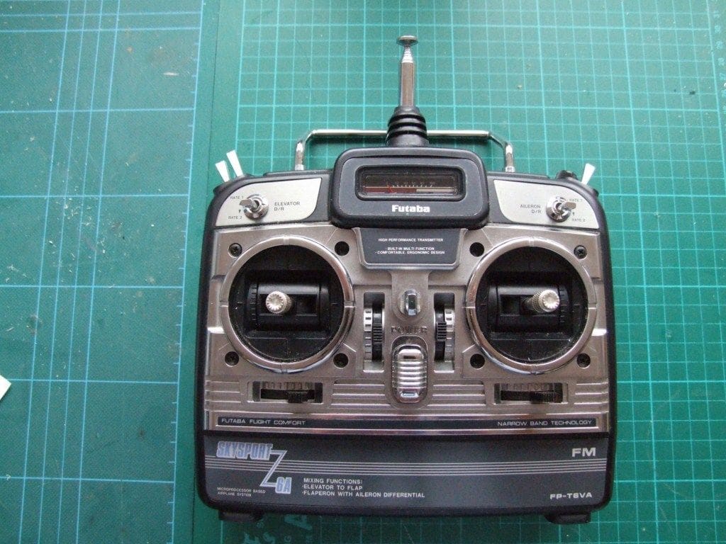
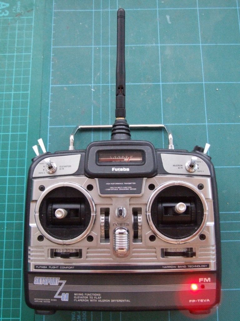
I have a variety of radios including Futaba, Hitec, Fleet and Multiplex, but more important, I have a Sky Sport Six 35MHz which could not be used for model boating purposes, so this would be my ‘test’ transmitter for the modification. Transmitters can be modified in two ways. If the transmitter is fitted with an external module, normally used to switch from 35 to 40MHz, then a 2.4GHz module may be used as a ‘plug in’ conversion. If the transmitter is not designed for an external plug in module, then a ‘hack’ modification can be fitted internally, subject to space inside the transmitter case and the skills of the installer. The Sky Sport Six 35Mhz as in Photo 1, would require an internal ‘hack’ module.
I chose a FrSky 2.4GHz ‘hack’ module from Giant Cod (£11.18) plus a seven channel receiver (£13.42) which together with carriage cost a total of £27.47p, so not too bad I think thus far!
There appears to be no compatibility across 2.4GHz systems; for instance Spektrum transmitters can only be used with dedicated Spektrum system receivers and the same applies with Futaba and Planet, etc. There are of course some generic receivers in the marketplace that are compatible with a particular brand, but you can’t use a Spektrum receiver with a Futaba transmitter for example, because they use different frequency-hopping systems.
FrSky has its own system, namely: Advanced Continuous Channel Shifting Technology, or ACCST for short.
Receiver
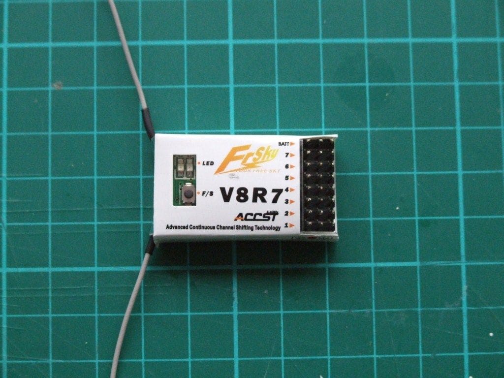
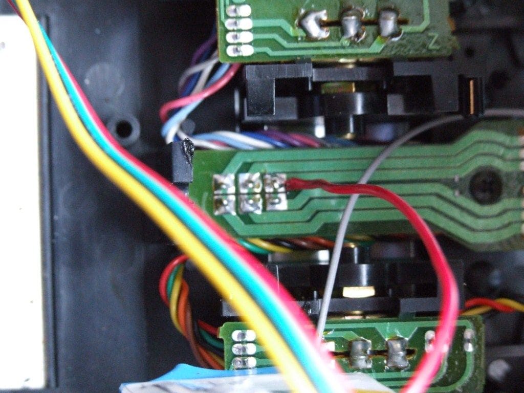
The seven channel £13.72 receiver had the typical 2.4GHz twin aerial arrangement on one side and the servo and battery connectors down the other as in Photo 2. A clear window in the flexible plastic case revealed the bind LED and its button. The case was flexible enough for the button to be depressed, but additional packaging and protection would be required to render the receiver waterproof.
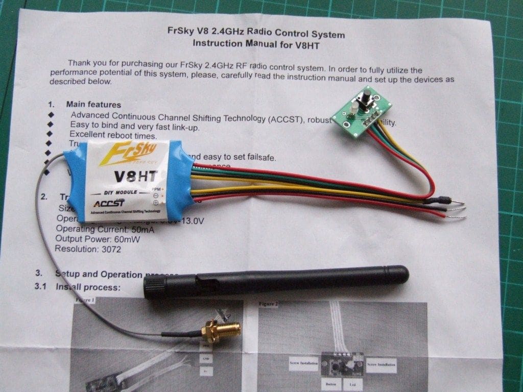
The transmitter module was supplied with an aerial lead and a pre-wired bind button board and lead, as well as a wiring harness consisting of three fine cables, Photo 3. The short dumpy flexible aerial cover was also supplied. A single sheet of instructions was also supplied.
Installation
The transmitter didn’t have a battery fitted and if it had, this would be the first thing to remove. The back cover of the transmitter was removed and put to one side which revealed the inner workings, Photo 4.
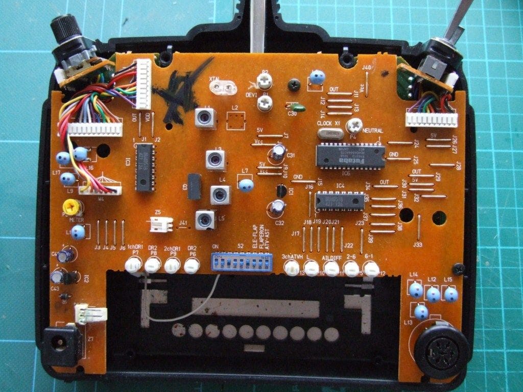
The screws holding the main printed circuit board in place were removed and the PCB pivoted gently upwards, its the wiring harness still attached which revealed the copper tracks on the underside of the board.
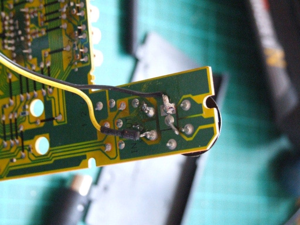
There are three connecting wires on the ‘hack’ module; red (positive), black (negative) and yellow (signal). The two power supply leads, red and black, are reasonably straightforward connections. The yellow signal wire is the more difficult as a source for the signal has to be found. The signal most transmitters use is PPM (Pulse Position Modulation) so when researching the signal information about the transmitter, this is what to look for. The internet came in handy at this point and I found a site that dealt with ‘buddy box’ connections which identified where I could connect the signal lead as my transmitter had a ‘buddy box’ connection. The signal lead (which has a diode already soldered to it) was soldered to the back of the ‘buddy box’ connector which was marked as the ‘OUT’ terminal.
The ‘buddy box’ negative track was used for the negative connector, Photo 5.
With two of the three wires connected, the red (positive) lead was soldered to the main ON/OFF switch, Photo 6.
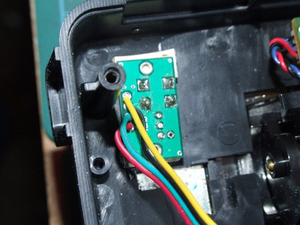
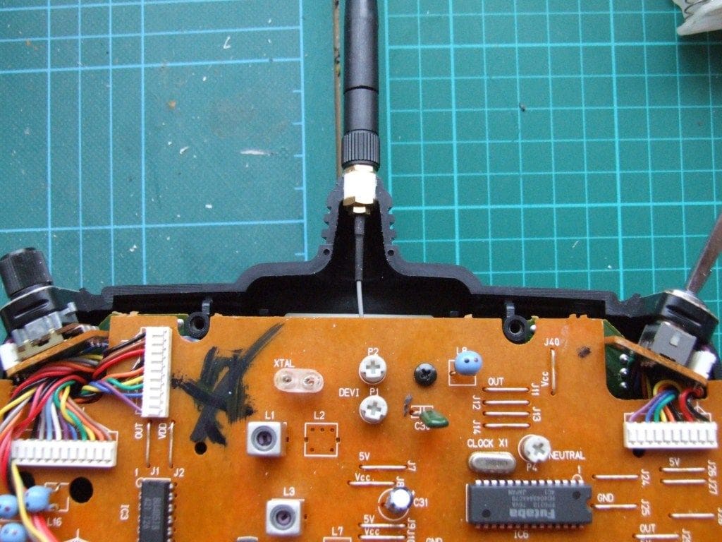
The next stage was to drill the case and mount the ready wired bind board so that the LED was visible and the bind button could be depressed. The bottom left of the case was chosen, clear of the battery compartment. Two holes were drilled 3.5mm in diameter with the correct spacing for the two components to protrude through the case. Balsa spacers were used so that the button and LED protruded sufficiently to be used, but not do far that they may get damaged or pressed accidentally. The board and balsa spacers were superglued in place, the logic being that if the board had to be removed at any time it would be easy to split the balsa away. It also avoided two more mounting holes for the PCB in the front of the transmitter case, Photo 7.With the original TX 35MHz aerial removed, the new supplied dumpy aerial was fitted in its place, Photo 8. The brass aerial fitting itself is already wired to the ‘hack’ module. The previous 35MHz or 27/40 MHz system is disabled by the removal of the aerial and the transmitter crystal.
The main PCB was now refitted, a charged battery connected and the transmitter turned on. The receiver was then switched on and the binding sequence followed and surprise, surprise, it all seemed to work okay! The failsafe was also set and tested and Photo 9 shows the completed transmitter.
Conclusion
I must emphasise that you must be reasonably competent with a soldering iron to carry out this modification. I modified an old 35MHz transmitter that had little or no value to me which made it ideal for testing the modification. There are several websites that will help to identify the PPM signal should you wish to modify your transmitter. Finding the power supply points require a basic voltmeter, but finding the signal without an oscilloscope means you will have to find the relevant information elsewhere. It is wise to do proper range checks as well prior to your intended usage, but for me it has worked fine with a scale boat at the distances one would normally sail from the pondside. For less than £28 I have ended up with a working six channel 2.4GHz system using a redundant 35MHz transmitter, and that can’t be bad.
Two useful websites
This was the supplier of the ‘hack’ module.
2) http://users.belgacom.net/TX2TX/tx2tx/english/tx2txgb7.htm: