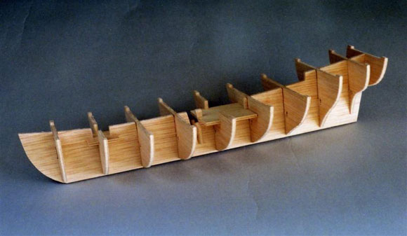
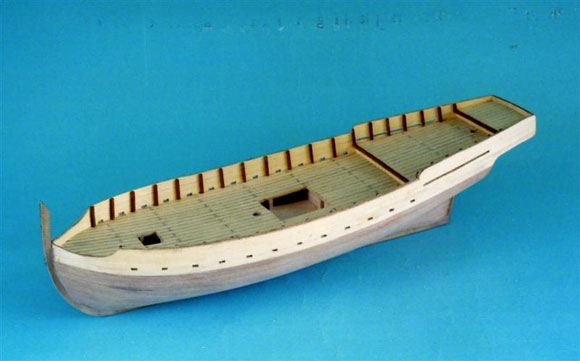
Pic 1: The basic hull framework. Pic 2: All decks in place with shaped battens in position. Pic 3: The inside surfaces of the bulwarks and transom lined before assembly. Pic 4: The stanchions are positioned between scuppers on main deck. Pic 5: The first planking trimmed to shape under the counter. A relatively new range of kits by OcCre, distributed by Ripmax Ltd. and now on the shelves, includes this well presented package for a Mediterranean style Felucca, a small two-masted vessel with bowsprit and a lateen rigged, forward raked, mainmast. The basic design of the vessel is one that has changed little over several hundred years and which was still being built well into the 20th century. Enjoy more Model Boats Magazine reading. Click here to subscribe & save. The kitI considered this kit to be ideal for the newcomer to the hobby. The instructions were linked sequentially to a series of photographs which guided the modeller through all stages of the build, indicating everything that had to be done and when. All individual parts were also numbered in sequence of use and cross-referenced to a comprehensive parts list. One large doubled sided drawing sheet put everything in to true perspective at 1:1 scale. All shaped parts were laser cut in ply and with one exception, were of adequate quality. The exception being the small panel containing the keel and stem parts. This I found to be of somewhat poor quality, not unusable, but in need of filling on the end grain surfaces. The strip and dowel material were of high quality, as were all the fittings contained within a twelve compartment plastic box. Of particular note was the provision of the sails, ready seamed and hemmed and a stand on which to display the finished model. Tools requiredOnly a very basic tool kit was necessary to build this model. I included a small plane, but a good file would have done the job equally well it would have just taken a little longer. Heavy-duty craft knife Making a startRead the instructions in conjunction with the pictorial manual and drawing as it always pays dividends. All the pre-cut parts were identified and the relevant part numbers marked on them before removing them from the host sheets. It was helpful to note that all parts are numbered sequentially in the order in which they are made up or assembled. The instruction manual, parts list and pictorial assembly book were also cross-referenced with the same numbers, an absolute boon for any newcomer to the hobby. In fact, ticking off each stage in the text and pictorial manuals as it was completed ensured that nothing was missed.
|
|
Pic 6: The keel, stem and rudder post added. Pic 7: The rubbing strakes and inner rails in place. The stand provides a good support for continued working. Pic 8: Some of the deck fittings. Pic 9: Deck fittings in position. The hull frameworkThe hull construction followed the conventional plank on bulkhead format where pre-cut bulkheads slot into a false keel. The slots were accurately cut and no adjustment for snug fit was required. A dry fit was done to make sure all was well before using white PVA adhesive to make the final assembly, Photo 1. A similar dry fit process was adopted for fitting the main deck. In this instance, I found that the pre-cut ply, Part 15, was a little too stiff to successfully glue in place due to the fact that it had to conform not only to the deck camber but also to the fore and aft sweep of the deck. This was simply overcome by pinning and gluing the ply deck in place before planking. The pins were removed after the glue had dried, although if the heads were punched under-flush, they could be covered by the planking. Planking the deck in situ was not a problem, since I chose to blacken one edge of each planking strip with a felt tip marker pen before assembly. I started at the centre line and worked outwards and having trimmed the outside edges to shape, I rubbed down the whole surface and marked the butt joints of the planking with a fairly soft grade pencil. I then gave it a protective coat of clear matt varnish. The remaining decks and the exposed bulkhead surfaces were similarly planked and assembled, Photo 2. The plank supports (battens) were then glued in place and the areas under the counter were planked. I found that it was easier to roughly shape the battens before assembly, but this was purely a matter of personal choice. Either way, sharp tools are essential for safe and accurate work. This shaping was done in conjunction with the bevelling of the bulkhead edges, necessary to provide a full width seating for the planking. A half-round wood file or a Permagrit abrasive tool was ideal for the job. A planking strip for regular checking was helpful. This was not a job to be rushed, as proper seating of the planks was essential for a good job. Having read the instructions beforehand, I realised that at a later stage, the back edge of the false keel, (on to which the rudder post is ultimately to be glued), has to have a thickness, after planking, of 4mm. To avoid thinning down the planking to almost nothing, I decided to reduce the thickness of the false keel to 2mm before planking. The bulwarks were lined and the scuttles profiled, remembering that one left and one right-handed piece was required. These sub-assemblies were then pinned and glued in place ensuring that the lined surfaces were to the inside of the vessel. The transom was made up and assembled in the same fashion, Photo 3. Thirty-four stanchions were cut over-length and glued in place. On the main deck they were positioned centrally between the scuttle apertures and on the quarterdeck, their positions measured from the drawing. Once the glue had thoroughly cured, the ends were cut and filed flush with the top edge of the bulwarks. PlankingIt should be remembered, that on this particular model, the first planking does not have cosmetic priority and the basic object of this stage was to provide a sound base for the thinner finishing planks. It was important however, to ensure that the planking strips were properly seated and pinned and glued to the edges of the bulkheads. Pins were left heads up to make it easier to remove them after the PVA glue had thoroughly cured. The planked hull was rubbed down and a 4mm wide flat established for the stem and sternposts. The stanchions and completed first planking is seen in Photo 4 and the stern detail under the counter is in Photo 5. The second planking required contact adhesive to attach the 0.6mm thick material. The outer surfaces of the bulwarks were planked first, followed by the hull starting at the keel and working upwards. Having covered about half the depth of the hull, the instructions then advised you to plank from the undersides of the bulwarks and work down towards the keel. The gaps where the two stages of planking meet were filled in with specifically shaped strips. All surfaces were rubbed down smooth and the stem, keel and sternpost glued in place, Photo 6. I found that these parts needed a lot of filling on the exposed end-grain surfaces to fill in a myriad of small holes. Finishing the hullRubbing strakes were attached to the outside of the hull and pin rails glued to the inside of the bulwarks, Photo 7. Cyanoacrylate was used for these parts, keeping them in place with clamps and crocodile clips until the glue had properly cured. All surfaces were then given a couple of coats of matt varnish. This was a personal choice as some modellers will possibly prefer a satin finish. Fitting outEach of the deck fittings was treated as a separate mini project. Constant reference to the parts list was necessary to ensure that the right size of material was selected, particularly for the deck cabin. Generally speaking, the manual was very clear as to what was to be done, although I did find the two pumps a little awkward to make. Most of the deck fittings can be seen in Photo 8. Some of the parts needed to be painted and this was done before fitting them to the deck, Photo 9. The two small boats and the anchors were rigged in position to complete the construction of the hull. The kit provided parts for a basic cradle style stand, which was assembled, stained and varnished.
|
|
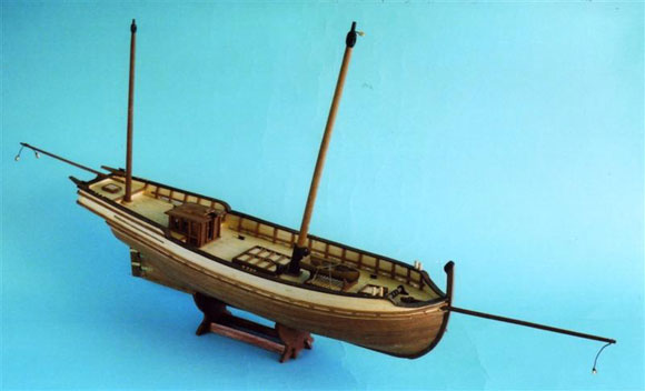
Pic 10: The masts and bowsprit dry fitted to check alignment. Pic 11: The standing rigging. Pic 12: The lateen rigged main and mizzen yards with sails rigged. Pic 13: The rigged main sail. Masts and sparsThese were relatively straightforward to make with not too much tapering to do. I used a small David plane and a file, spinning each part in an electric drill for final sanding. The mastheads were drilled and pinned and glued to the tops of the masts for added security using brass wire pins and cyanoacrylate glue. Rigging blocks were put in place, as were the parral trucks and beads before assembling either the masts or the bowsprit to the hull. The sequence of adding the masts and spars is outlined in the manual and is done in a manner designed to maximise accessibility for hands and fingers during the rigging process. The masts, dry fitted in position are shown in Photo 10. RiggingThe standing rigging was put up first. The stays to eyebolts in the bows stabilised the bowsprit, and the shrouds either side of the two masts to rings on the bulwark capping rails basically completed this section of the rigging, Photo 11. The only challenge was to make all fourteen block and toggle assemblies the same length and to get some sort of symmetry to the tackle that tightened up the shrouds. The two lateen yards were fitted to their respective masts with parrals and the halyards rigged to deck. The vangs on the mainmast yard were also rigged at this time. The boom sheets were then rigged to eyebolts fitted to the hull below the counter. The manual contains a belaying plan adequately cross-referenced to identify the correct belaying points for all rigging. The fore, mizzen and main sails were put up in sequence together with their very simple rigging. Photos 12 & 13 record these procedures. ConclusionsThis was a great kit for the less experienced, in that it provided a good insight and a worthwhile introduction to the building of static model plank on frame boats. The result was a neat and tidy model, which although simple to build, provided a reasonable challenge to maintain interest in the project. I did not like the quality of the sheet material for the keel, stem and rudder (OcCre No. 12001-5), but having said that and having employed a suitable filler, all parts were used successfully. (Ripmax have spoken to the manufacturer and further wood quality control is now in place Editor, March 2008) The combined instruction manuals and drawing were excellent, leaving the modeller in no doubt as to what needed to be done, and when. The inclusion of ready-made sails was a boon, these being features that so often spoil a model when poorly made by hand. All in all, an excellent package for the beginner and good value for the retail price of £69.99. Ripmax distributes OcCre kits to most good hobby outlets.
|
Felucca
Enjoy more Model Boats Magazine reading every month. Click here to subscribe.
Article Tags:

