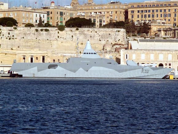
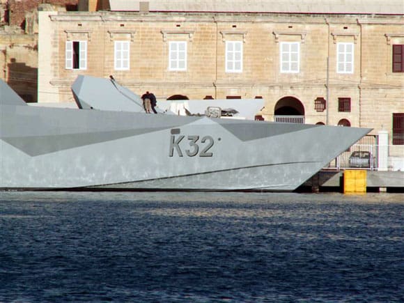
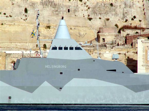
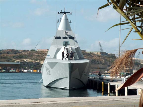
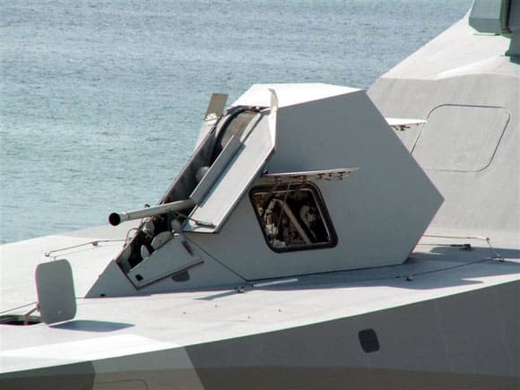
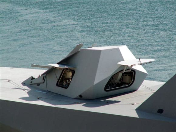
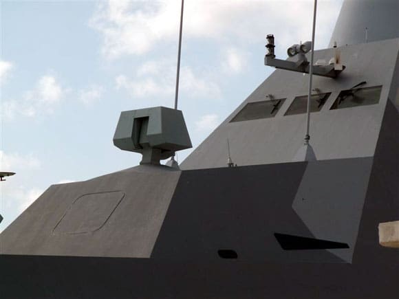
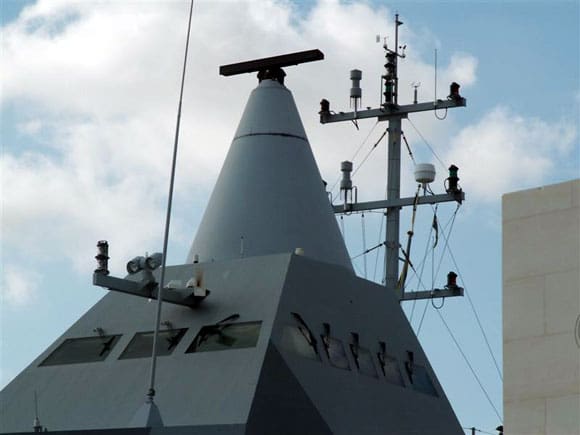
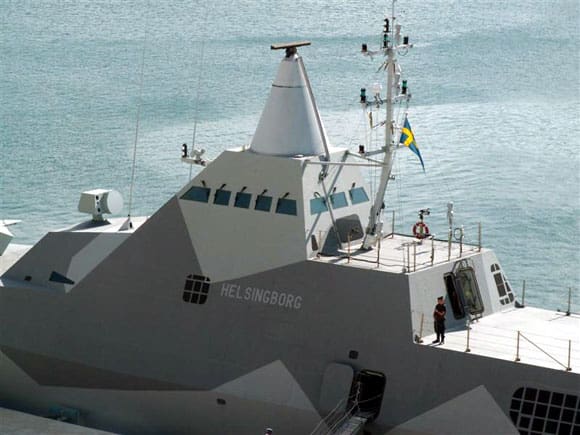
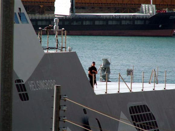
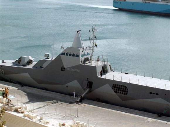
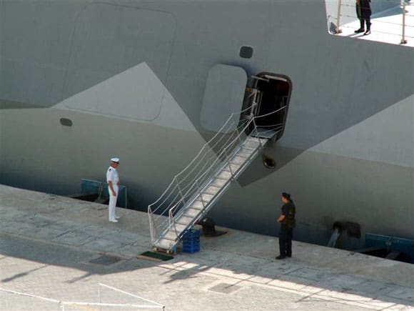
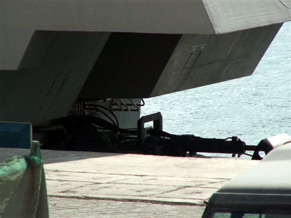
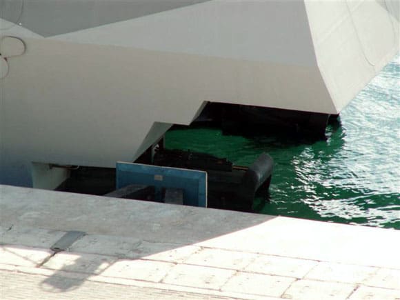
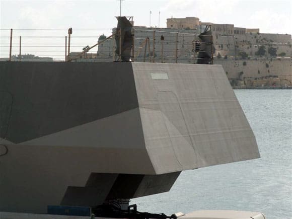
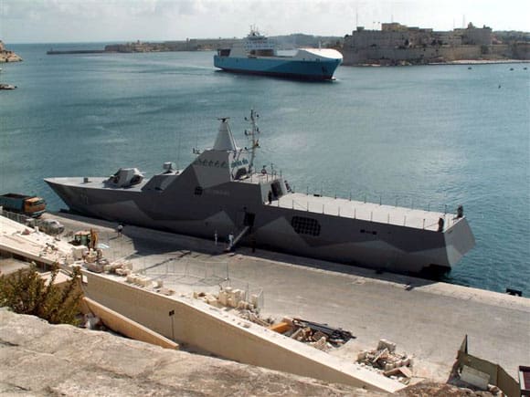
Pic 1: Helsingborg, a Swedish Navy Visby class corvette. Presently one of the most advanced stealth warships and reputed to be almost invisible in a combat scenario. Pic 2: A hull design that owes much of its shape to a more conventional hardchine design. Pic 3: Bridge and foremast almost as one and a departure from conventional design. Pic 4: A more recognisable hull in this shot of the bows showing the spray rails. Pic 5: Helsingborg is fitted with 57mm dual purpose gun. Pic 6: The gun turret is radar reflective. Pic 7: The optronic director. Pic 8: Conical housing for the multi role surveillance radar. Note the mast and navigation light arrangements. Pic 9: Even the mast is shaped in such a way as to reduce its own radar cross section. Pic 10: Looking carefully at the base of the stanchions it will be seen that those on the afterdeck can be dropped down.
Welcome once again to our regular sortie into the world of fighting ships. For the first time in any publication, we have a detailed research photo file on Helsingborg, a Swedish Visby class stealth corvette. We also continue with the build of the Soviet Aviation Cruiser Kiev, plus our Mystery Picture slot.
The Guided Missile Patrol Vessel – PGG K32 Helsingborg
Since the Visby class entered service, much has been written regarding these ships being the first commissioned warships with the ability to be actually invisible to radar and indeed across the electro magnetic spectrum.
Enjoy more Model Boats Magazine reading.
Click here to subscribe & save.
Invisibility – fact or fiction?
Since the dawn of war at sea, inventors and military thinkers have dreamed of warships being invisible to the enemy. In WWI this took the form of camouflage that used deception as its prime element, with ships being painted in stark dazzle patterns able to deceive the enemy as to the direction, speed and range of the vessel. By the end of WWII the techniques of camouflage had been refined to allow a ship to be concealed within the environment. In many ways this mimicked the natural world, where light and colour are used to blend with the surroundings and produce a form of invisibility.
Radar
No matter how effective the camouflage, the introduction of long-range surface search radars such as the Type 271 and later the Type 277, altered the equation. No longer could a camouflaged vessel remain undetected. So, following WWII and into the Cold War, it was considered unnecessary to retain the elaborate camouflage patterns developed for wartime. Equally, little thought was given to reducing the so called RCS (radar cross section) of vessels. Thus for many years after WWII, warships were relatively easily to detect with surface search radars such as SPS 5 and SPS10 and later developments in surface search technology pushed the detection boundaries out still further. Once detected and located, a warship was vulnerable to either surface attack, by gunfire initially then long range surface to surface missiles such as Harpoon or Exocet MM38 as they were developed, or indeed by submarine attack.
However, before these weapons can be deployed, the target has to be found, hence the developing need to reduce the RCS value of a given warship and to reduce or eliminate the residual levels of acoustic and electro magnetic emissions, for example IR (infra red) and to employ passive ECM (electronic counter measures).
Reducing radar cross section
Radar cross section is the most obvious for reducing a warships signature. It’s difficult to define exactly when there was a realisation that the profile of warships needed to be changed to reduce the possibility of detection. However, probably it was Soviet Union that started to understand the advantages of reducing a ship’s radar signature by inclining the faces of the superstructure, incorporating enclosed sloping masts and reducing rounded corners. This was noticeable in such vessels as the Kresta and Kara class cruisers and the large aviation cruiser Moskva, all designed in the late 1950’s and early 1960’s.
Since that time, most navies, particularly the USN and RN, have refined their designs to reduce significantly the RCS values of their warships. However reducing RCS is not the only way to reduce a ship’s susceptibility to detection. The very fact that the ship is moving is an indicator that other forms of emissions are in play and detectable. It is here that the designers of the Visby class looked to eliminate or significantly reduce the ships signature at all levels of detection. Interestingly what has evolved is a warship that in many respects departs from the accepted norms of warship construction and takes on an appearance that is far removed from what would be termed a traditional design, Photo 1.
In the initial design. the hull was to have been of an ‘air cushion’ type, similar to the guided missile patrol boat Skjold of the Norwegian Navy (February 2003 MB), but this was changed to a more conventional hard chine hull. Helsingborg which is the subject of our photo file was built by Kokums/ Thysens Krupp Marine, launched on June 27th 2003 and commissioned into the Swedish Navy in July 2005. So far, five of these vessels have entered service, K31 Visby, K32 Helsingborg, K33 Harnosand, K34 Nykopingand and K35 Karlstad.
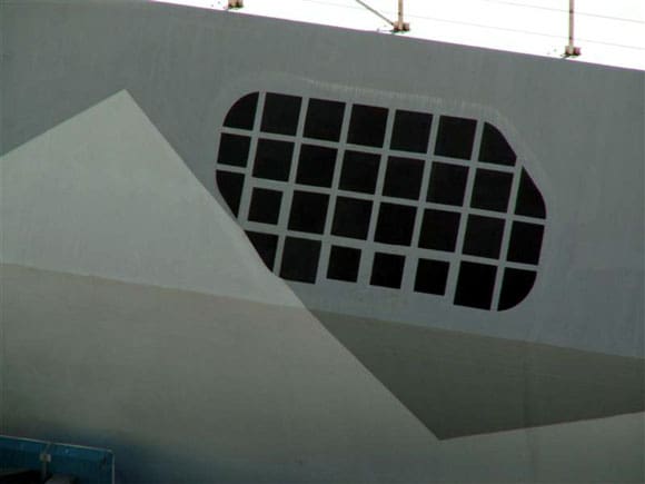
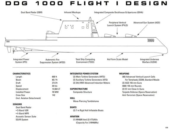
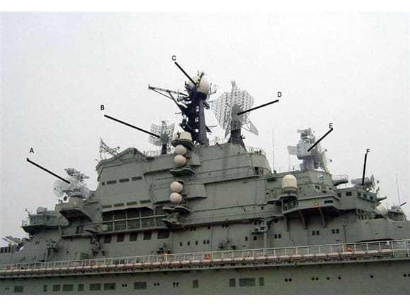

Pic 11: Helicopter operations are not available on Helsingborg, but the flat area aft of the superstructure is designed for such operations. Pic 12: Part of the hull covered with a panel. It’s purpose is unknown. Pic 13: Immediately to the left of the gangway opening and above the knuckle line is a much larger covered opening. Pic 14: Visible under the stern overhang is the water jet arrangement. Pic 15: Note how the stern is fitted with a series of steps. Helsingborg is also equipped with bow thrusters. Pic 16: Set into the stern is the covered opening for the passive towed array sonar. Pic 17: The Visby class and Helsingborg in particular may not be aesthetically pleasing warships, but if you can’t see them does that matter? Pic 18: Zumwalt DDG1000, a future stealth warship due to enter service with the USN some time after 2012. Pic 19: Following the basic construction of the superstructure, the next stage for Kiev were the radar arrays. Pic 20: Please refer to the text for the names of the marked radar arrays on Kiev. Pic 21: The Head Light tracking radar.
The hull
The Visby class uses a mono hard chine hull, which in some respects is quite traditional for patrol vessels, yet that is where the similarities end. The construction method makes use of carbon fibre in a sandwich with PVC foam. This composite material has strength equal to steel, but unlike steel possesses qualities that are ideally suited to reducing IR, magnetic, electrical, hydro-acoustic and acoustic signatures. The shape of the hull can be seen in Photos 2, 3 and 4. The Visby class are 650 tons full load, 72.80m in length x 10.40m in beam, complement of 43, and are the largest vessels built using this material and method of construction. It was envisaged that twenty would be required, but due to cost overruns and technical difficulties this was reduced to six, with only five actually entering service.
Armament and fire control
Four of the class are equipped for mine hunting. Helsingborg, as with the rest of the class has a 57mm/70 calibre Bofors gun housed in a low radar visibility turret, Photo 5. The barrel is water-cooled and can be retracted into the turret when not in use, reducing further the radar signature. The gun is capable of 220 rounds per minute using programmable proximity fused rounds. The barrel is fitted with its own sensor, which measures muzzle velocity, an aid for more accurate fire control which ensures better targeting and hitting frequency, Photo 6. Although not shown here, Helsingborg has provision for retro-fitting the RBS 15 Mk3 SSM for anti ship defence. How and where these SSM launchers are to be fitted remains restricted information. Immediately aft of the turret housing is the rather innocuous Ceros 200 (an optronic director) for fire control, Photo 7. Also fitted within the hull are 4 x 400mm ASW fixed torpedo tubes with torpedoes being launched from a concealed opening amidships.
Radar fit
Moving further aft is the rather unusual bridge come foremast, which may resemble a traffic cone on a roof, but this does the job of masking its presence. Housed within the tall conical mast is the Sea Giraffe 3D multi role surveillance radar for tracking air and surface targets, Photos 8 and 9. Note that the mainmast, housing the navigation lights and ECM is also carefully shaped to reduce detection by radar.
Aviation
Provision for the operation of helicopters takes the form of a small flight deck aft with a hangar space below deck. It is understood that this is only available from K33 onwards, and Helsingborg may be retro-fitted at some later date, Photos 10 and 11.
Anti-ship missiles
The Visby class are designed to be fitted with eight RBS 15, a 595kg anti-ship missile or a navalised derivative of the RBS-23, called Bamsea which has been in service with the Swedish coastal defence forces since 1993. The launchers will be located internally, but little information regarding these are available. Photo 12 is of a hull mounted cover panel – its purpose unconfirmed.
MCM (mine counter measures)
The first four of the class an equipped for mine hunting and support a number of ROV’s (remote operations vehicles). Two Bofors Double Eagle mine location vehicles, and two Seafox mine disposal vehicles, are deployed through doors in the side of the hull. Additionally a further Swedish manufactured ROV will be added in due course, designed specifically for underwater reconnaissance. The hardware is interfaced with the Hydra hull mounted sonar and a passive towed array. A covered hatch in the side of the hull is just visible, Photo 13 in front of the gangway.
The stern
The final sequence of pictures focuses on the stern and the water jet drive. I think for the first time in any publication this is a chance to view the drive system, primarily the twin jet propulsion units. These can develop 21460 shp and are officially recorded to give a performance of 34kts continuous, although this figure may well be conservative. The engine arrangement is CODOG, which translated means ‘Combined Diesel or Gas Turbine ’ propulsion. The vessel can maintain 15kts on diesel drive only. Note the stepped stern, which reduces the rooster tail effect, Photos 14 and 15.
Our penultimate picture is of the stern and once again this gives us a reminder of the purpose of the design. Incidentally the surface of the entire vessel is covered with a radar absorbent material, which is just visible in this picture, and note the stern door for the deployment of the towed array, Photo 16. Finally, our last picture is a rather good shot set of course in the majestic surroundings of Grand Harbour, Valetta, Malta. This type of warship is indeed the first of the true stealth ships and as a reminder of this when cruising at sea, her radar beacons are deployed so she becomes visible to passing ships, Photo 17. I would like to express my sincere thanks to my good friend Mario Camilleri for providing this sequence of pictures.
Pic 22: Each basic reflector for the Head Light radar is moulded to shape using zinc mesh. Pic 23: Each of the major components forming the Head Light array. Pic 24: Styrene tubes formed the basic material for the pillar that supports all the parts associated with this radar. Pic 25: These pannier like boxes are fitted accurately by inserting pins, which are pre-located into the pillar. Pic 26: Stabilising fins to be fitted to each box. Pic 27: Assembly of the upper frame supporting each of the smaller radar dishes.
The future
Yes, the Visby class can reduce all the signatures that make the ship visible to radar and other sensors, but new methods to detect such a warship will inevitably be developed. Where there is one measure deployed, then there is bound to be a counter measure created. However as a footnote to the whole area of stealth technology and the continuing search for the invisible warship, the USN have developed and are building the Freedom class of Littoral combat ships of corvette size and the Independence class, both of which possess many of the features attributed to the Visby class, but are much larger.
By far the ultimate stealth warships, but with protracted development, are the Zumwalt DDG1000 programme of eight 14564 ton ships for the USN. With their long range twin turreted 155mm advance gun system and an assortment of surface to surface and surface to air missiles, these ships are destined to become the most formidable ships of their type ever built, Photo 18.
Part Seven – The building of the Soviet aviation cruiser Kiev at a scale of 1:144
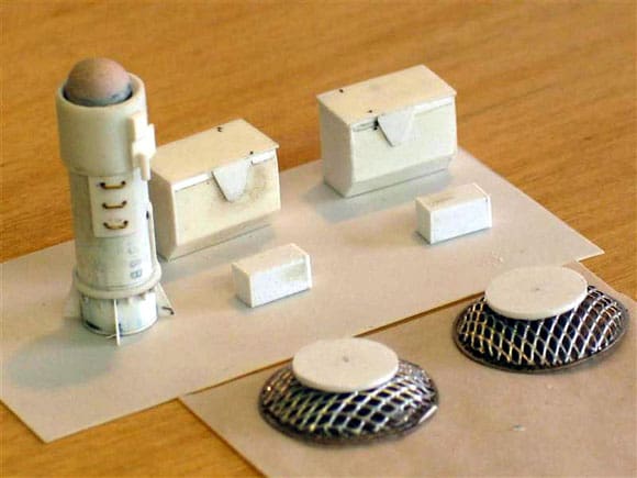
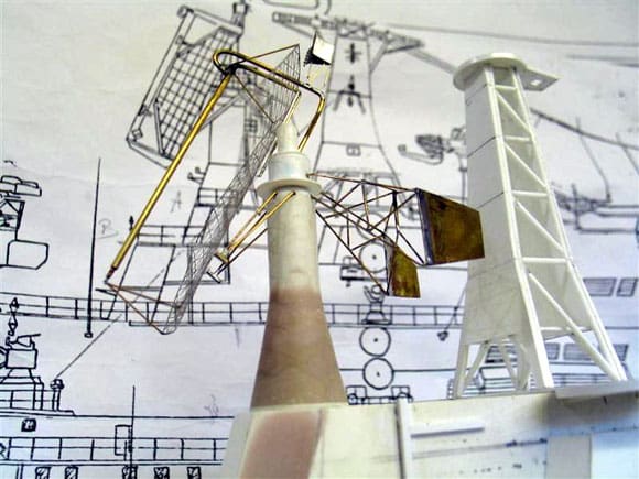
Last month saw the construction of the lattice support mast for the Top Knot radar sphere and the preparation of a large number of the smaller, but more mundane fittings. Attention can now shift back to the island superstructure and the construction of the twin Head Light tracking radar and the prominent Top Sail 3D air search radar array, Photo 19.
Making the radars
To assist in identifying the various radar arrays I’ve included this starboard side shot of the island superstructure of Kiev with each individual radar highlighted, Photo 20. These are as follows: A + E are Head Light target tracking radar, B is the Top Steer long range surface search radar, C is the Top Knot tactical air navigation, D is the Top Sail long-range 3D air search radar and F is the Owl Screech gun fire control radar.
Head Light radar
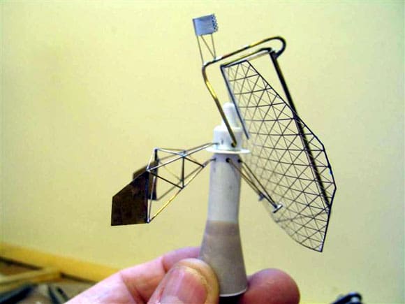
Kiev, Project 1143 was a direct descendant of the Moskva, Project 1123, and as such there was a strong commonality of radar and weapons. Fortunately the construction of the radars for Kiev was not so daunting as would first appear, as I had gained experience constructing similar arrays on a 1:128 scale scratchbuilt model of Moskva a few years ago. I decided to commence work first on the Head Light radars. Essentially the purpose of this large cluster array was to function as a missile control radar for the SA-N-3 surface to air missiles. Viewing this radar closely it will be noticed that the array contains two large dishes of 4m diameter and two smaller dishes of 1.8m diameter mounted above each other. In operation the large dishes track the target whilst the smaller dishes track the missile, Photo 21.
Making the reflector dish
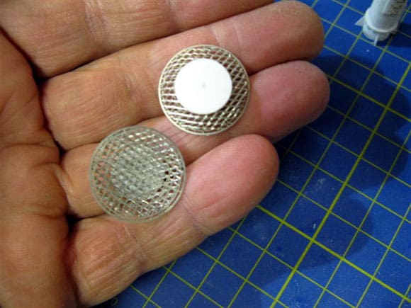
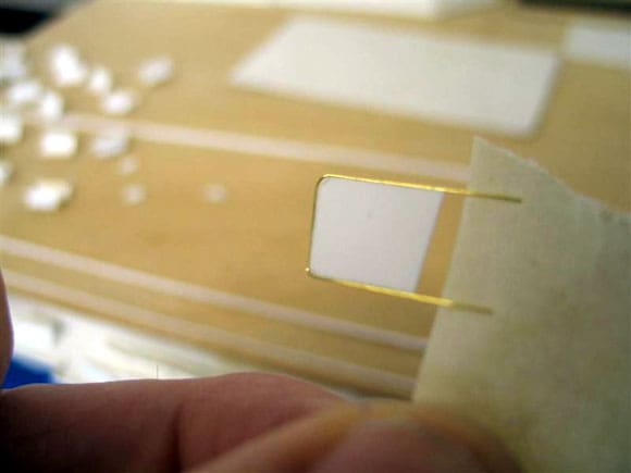
The method for making each of the twin reflector dishes was explained in the March 2000 issue of Model Boats and in the book ‘Warships and Warship Modelling’. Briefly though, to acquire the shape and basic appearance, zinc mesh is used, similar to that available at any car accessory outlet and used in car body repair. This material is so malleable that it can be formed into a dish shape without distortion. A very basic flat photo-etched main circular reflector was actually included as part of the original kit. As I am never one to waste perfectly good photo etchings, this was incorporated into the curved zinc mesh dish, which added to the overall appearance, Photo 22.
Radar support pillar
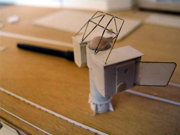
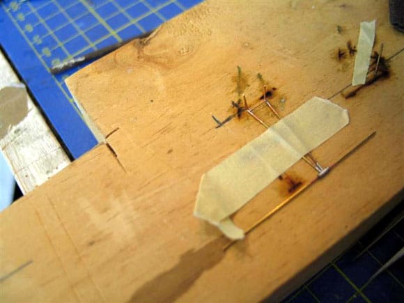
Each of the components that make up this rather complex tracking radar were made ready for assembly, Photo 23. The main support pillar is made up using a series of styrene tubes readily available in the Evergreen range (11.1mm and 12.5mm dia.) fitted one over the other. The dome shape at the head of the pillar was formed using a curved cheese head bolt, treated with filler and then gently sanded to form a smooth dome effect. This was then inserted into the tube with the remainder of small fittings added, as in Photo 24.
Pic 28: Completed Head Light array. Pic 29: For modelling the Top Sail radar array it was intended to use a purpose made frame to support the delicate photo-etched reflector. Pic 30: The completed frame ready to accept the reflector. Pic 31: Although following a similar construction process to those constructed for the Moskva, trying to juggle between scale appearance and maintaining strength was difficult and in the end a fruitless exercise. Pic 32: Top Sail was fitted with two stabilising fins. Pic 33: An inverted ‘V’ frame as per the photograph was soldered in place. See text as to how this was done without melting the plastic or de-soldering existing joints. Pic 34: Soldering one of the twin arms that provide support for the delicate PE reflector. Pic 35: How each of the arms supporting the reflector is located. Pic 36: Almost completed! Pic 37: Mystery Picture.
Pannier style boxes and stabilizing fins
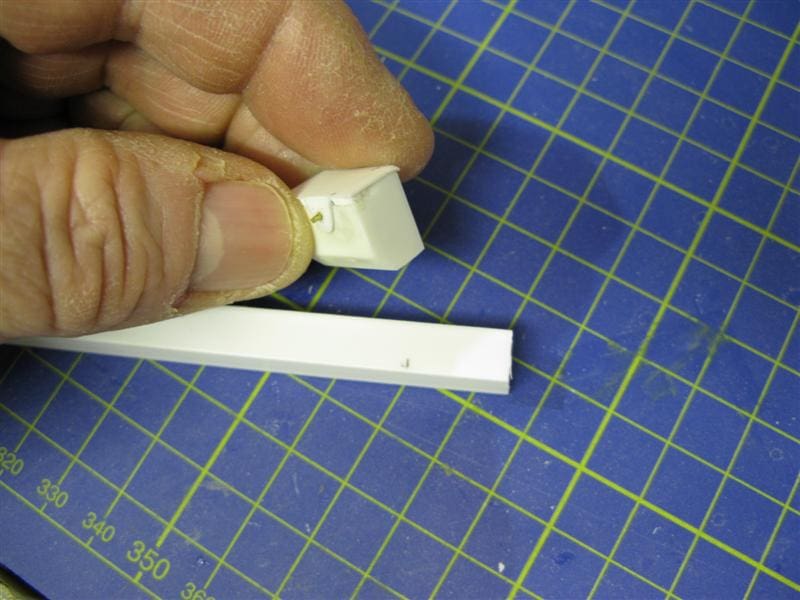
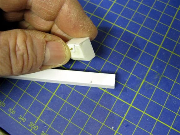
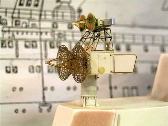
The two boxes, which are mounted pannier fashion either side of the pillar are made initially from Evergreen box section No. 255, 7.9mm sq. and it will be noted that the underside is splayed. To ensure that each box is located correctly, pins were inserted into the inside upper face, Photo 25. A good and accurate fit between each zinc moulded dish, and their respective box is achieved by fixing a styrene roundel to the back of mesh dish. The stabilizing fins are made using 1/100in (0.25mm) styrene surrounded by 0.4mm brass wire, Photo 26. The entire fin of course could be made from equivalent brass shim and soldered. Once the fins are made and fitted, work can begin on the upper frame surmounting the top of each box as in Photo 27. To produce this framework, it can be done by making a jig from solid timber which conforms the inside shape of the whole frame, then each side is soldered together on the jig. This was explained in some detail, accompanied by photos in ‘Warships and Warship Modelling’. Alternatively each of the four sides can be cut to size, soldered up separately on a marked and flat timber profile and then each of them are fitted and soldered together in situ. This can be done by affixing heat shunts (appropriately sized paper clips) to each leg. Finally the upper two radars arrays are semi-moulded using a circular styrene disk, cut and formed into a bowl shape. Filler is added and when set carefully sanded down and fitted to the smaller box shape sections, which also have their own dedicated stabilizing fins. The final result can be judged in Photo 28.
Top Sail radar (MR 600 Voskhod)
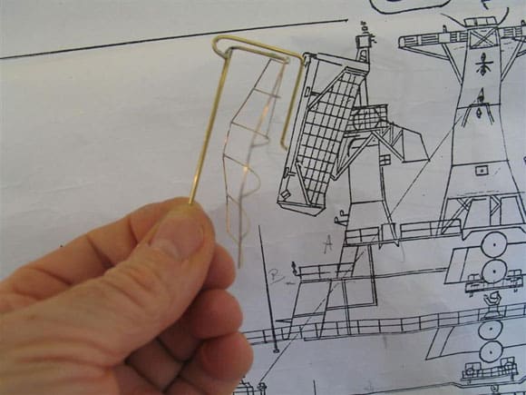
This huge radar array was first introduced in 1967 as a frequency scanning 3D radar search radar. Top Sail is a product of 1950’s technology and its 6.1m x 7.5m antenna was capable of detecting targets out to 500km. Once again this type of radar was covered as a totally scratchbuilt item in May 2000 issue of Model Boats. Here the approach is slightly different, as the main reflector was formed from a photo etching, thus the detail is very fine. However the support pillar and the basic frame that holds the reflector had to be fashioned from brass tube.
Building up the reflector
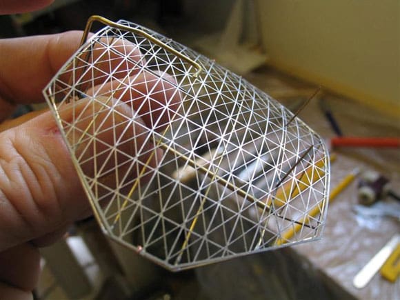
Before we move on I thought it would be an interesting exercise to mention a method used but later disregarded. Due to the fact that the photo-etched reflector at 1:144 scale was quite delicate. a decision was made to form a wire framework soldered up on a curved wooden jig that would hold the reflector to conform to the appropriate shape and curves. The method as such is well illustrated in ‘Scale Model Warships’, written by John Bowen, Photos 29 and 30. The idea was to spread the photo-etched reflector across the back of the frame and using very fine wire, tie the reflector into place, Photo 31. The method worked well, but the final scale appearance was not satisfactory. After due consideration, the reflector frame was de-soldered and a decision was made to secure the reflector only to the vertical arm, and this proved more successful.
Stabilising panels
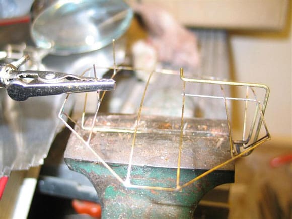
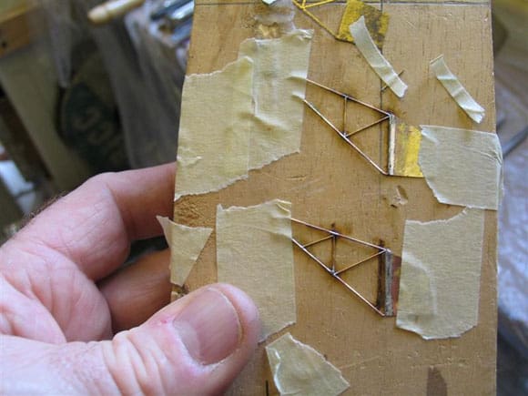
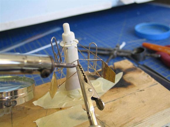
The Top Sail array is fitted with two stabiliser panels, cut to size using 0.5mm brass wire and 15/1000in (approx 0.4mm) brass sheet, see Photo 32. Both were then offered into position and secured at the correct angles by soldering into place an upside down ‘V’ frame as per the photos. As with other parts of the array, to avoid the possibility of de-soldering parts already soldered and stopping any heat generated from damaging the styrene pillar, the trusty paper clip was used to good effect. These are lightweight, convenient and really delicate soldering can be performed in this way by making use of various sizes of them. The more heat generated, then the larger the clip used and they actually work, as in Photo 33. The next stage was to measure and cut to size the twin elevation arms, which hold the reflector at the correct angle of 20 degrees. These were then transferred to a flat surface and soldered together. Note how the small section of brass tube is soldered to the intersection of the two arms. Once soldered, the holding wire is withdrawn from the tube, Photo 34, and the results of this can be seen in Photo 35. Finally, the near completed Top Sail radar is ready to complement the Top Knot lattice mast, Photo 36, but more about that next month.
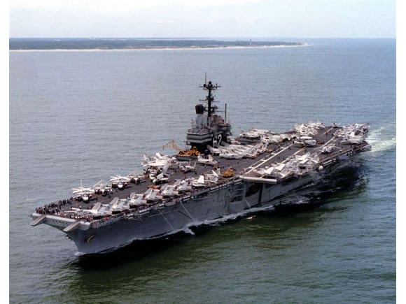
Mystery Picture – Photo 37
What was so special about this class of aircraft carrier?
References and acknowledgements
Visby class: Ref – Jane’s Fighting Ships 2008 and Naval Institutes Guide to Combat Fleets 15th edition.
Radar signature: Ref – Surface Warships, detection and counter detection, by Dr P.J Gates, pages 125 to 137.
Soviet Naval Radars: Ref – Guide to the Soviet Navy, fourth edition by Norman Polmar and Naval Radar by Norman Friedman, pages 186 to 189.
Kiev: Ref – Combat Fleets 1986-87, Soviet Warships by John Jordan pages 77 to 95. Warships and Warship Modelling by Wooley and Clarke: Ref – Top Sail and Head Light arrays.
Scale Model Warships by John Bowen: Ref – Jigs for making curved radar reflectors.
My thanks to Mario Camilleri for the Helsingborg photos and Bill Clarke for the mystery picture.