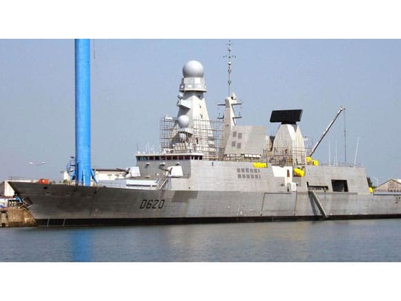
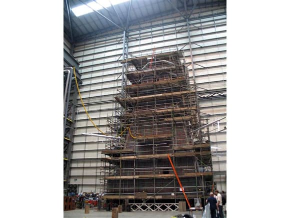
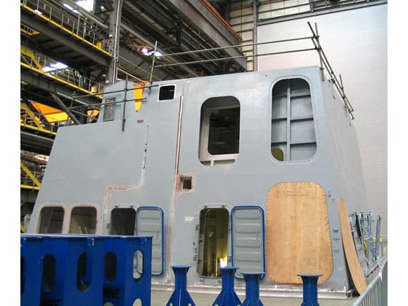
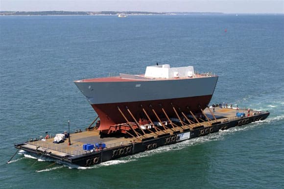
Pic 1: The French warship Forbin (D620), a Horizon Class DDG. Pic 2: Foremast of the Type 45 DDG H.M.S. Dauntless under construction at the VT facility Portsmouth. Pic 3: Part of the T45 amidships deck housing under construction. Pic 4: The forward section being transferred from VT Portsmouth to the Clyde (Picture courtesy of VT). Pic 5: The Launch of H.M.S. Daring in February 2006 (official picture). Pic 6: H.M.S. Daring leaving for trials. Pic 7: A good view of the uncluttered bow area. Pic 8: The new stealth turret housing of the Mk.8 114mm gun. Pic 9: VLS housing for the Aster missile system. Pic 10: The bridge and forward superstructure has a number of similarities to that fitted to the River class OPVs.
Welcome once again to our regular sortie into the world of fighting ships. This month has a photo file on one of the new Royal Navy Type 45 Class DDGs to undergo trials, plus I am continuing the build of the Soviet Aviation Cruiser Kiev. The new Type 45 air defence destroyer (DDG)
Probably one of the largest and one of the most sophisticated naval projects undertaken by UK ship builders at this present time. is the design and construction of the Type 45 AAW (Anti-Aircraft Warfare) DDGs. These vessels mark a new level in warship design and development and are the first new destroyers to be built for the Royal Navy in 22 years. The last new destroyer to enter RN service, was the stretched Type 42, H.M.S. Edinburgh, back in December 1985.
Enjoy more Model Boats Magazine reading.
Click here to subscribe & save.
It is envisaged that between 2009 and 2013, six of the new Daring class destroyers are to be commissioned. Beginning with H.M.S. Daring (D32) in the early part of 2009, followed by Dauntless (D33) and Diamond (D34) in 2010, Dragon (D35) in 2011, Defender (D36) in 2012 and finally Duncan (D37) in 2013.
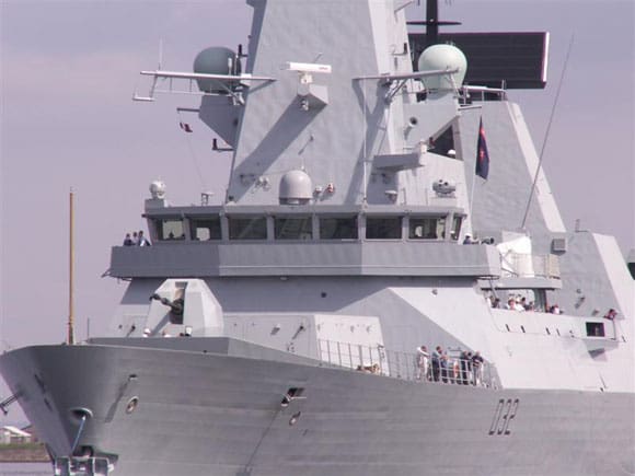
The Type 45 destroyer originally formed part of the Horizon project, a joint programme with France and Italy to produce a common design, Photo 1. This consortium involving the UK was dissolved in 1999. However the basic parameters of the Horizon project remained, with the core of the new UK project centred on PAAMS (Principle Anti-Aircraft Missile System). This is certainly the most advanced system of its type at the heart of which is the Sampson target tracking and illumination radar. This system is capable of tracking and engaging multiple threats. No doubt the exact capability of this system remains classified, although it is reputed to be highly resistant to any form of jamming. Central to the air defence role is the Aster missile system, supported by the Sylver A50 VLS (Vertical Launch System). The system combines an area defence missile, the Aster 15 and the longer range Aster 30. Although the term DDG is applied to the Type 45, the displacement, dimensions and capability are certainly that of a CG or what would have been called a light cruiser a few years ago. The hull is 152.2m long by 21.2m beam and has a full load displacement of over 7500tons.
Engines and performance
In recent months much has been written regarding the propulsion system installed in the these ships and there is also been some misunderstanding regarding what is meant by the official statement, The Type 45 (T45) is in effect an integrated full electric propulsion vessel. The T45 is indeed an all electric driven ship. The power plant consists of two WR21 gas turbines, which produce power for the propulsion units and a diesel power plant which is connected to an alternator for low speed cruising. The main drive is from two Alstrom direct drive 15 phase induction motors developing 53648shp and connected to two fixed blade propellers.
The turbines apart from providing power for the propulsion motors also supply power for hotel (accommodation) use and a single turbine is designed to run the weapon systems, meet all accommodation requirements and supply power for propulsion with a continuous speed of 18kts. According to official BAE reports, the performance and trials statistics of H.M.S. Daring are impressive. For example 0 to 29kts in only 70 seconds, remembering of course that this a vessel of over 7000 tons displacement. She recorded a measured top speed of 31.5kts on trials. For those with an interest in building a working model, the recorded turning circle or tactical diameter, is less than three ship lengths in total and that is a tight turn.
Weapons
Apart from the Aster missile system mentioned above ,the T45s are equipped with the well tried and tested Vickers Mk.8 114mm (mod 1) naval gun with a stealth configured turret housing. Upgrades have been planned, but as yet no firm decision has been made as to the exact replacement for the Mk.8 gun. Two single 30mm 75 calibre guns, two 20mm Mk. 15 mod. Phalanx CIWS and two twin 324mm fixed ASW Torpedo tubes complete the armament.
Views of the Type 45 Destroyer
The photographs are mostly of H.M.S. Daring. Methods of construction have evolved considerably over recent decades and this is very much in evidence when viewing the construction hall at Vosper Thornycrofts Portsmouth facility where sections of the T45s are being built. The foremast is one of the most striking features and it is shown here surrounded by scaffolding, Photo 2. Another section of the T45 that could be seen was the deck housing assembly that is to support the large communications EW mast, Photo 3.
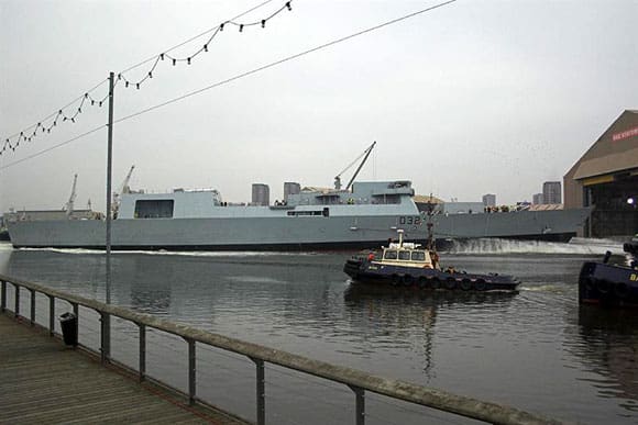
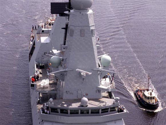
Once these sections are completed, they are shipped to the Clyde for final assembly on the slipway. The bow section incorporating the VLS housing is transported by barge to the BAE systems facility at Govan, Photo 4. Each of the sub assemblies is transferred to the slip and fitted into position. The T45s are dynamically (conventionally) launched and this is shown in Photo 5, as H.M.S. Daring heads down the slipway on 1st February 2006. Once fitted out, extensive sea trials can be undertaken. Here she is seen being guided down the Clyde, Photo 6.
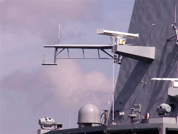
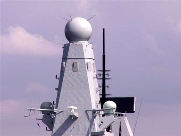

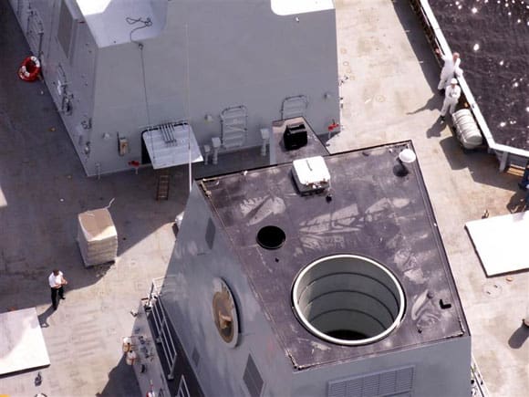
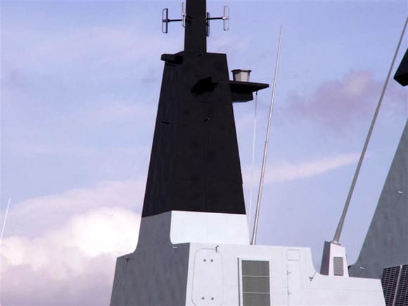
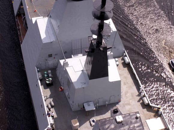
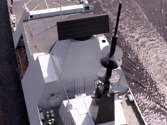
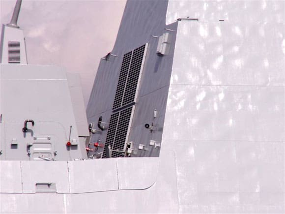
Pic 11: On top of the bridge. Note the Type 1008 navigation radar. Pic 12: The tall foremast with the Scott domes either side. Pic 13: Mounted on the bridge are the Radamec 2400 electro optical trackers. Pic 14: Crowning the top of the foremast is the SAMPSON 3D target tracking and illumination radar. Pic 15: A portside view of the foremast and uptake casing. Pic 16: An unusual but useful shot of the exhaust uptake. Pic 17: Deck housing support for the communications and EW array. Pic 18: Communications and EW array. Pic 19: The S1850M early warning radar. Pic 20: Ventilation grills sited at the base of the S1850 radar structure.
Detail pictures
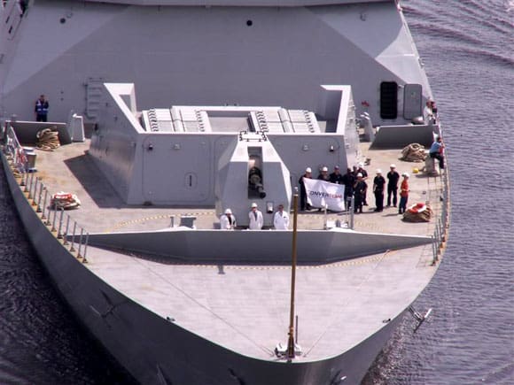
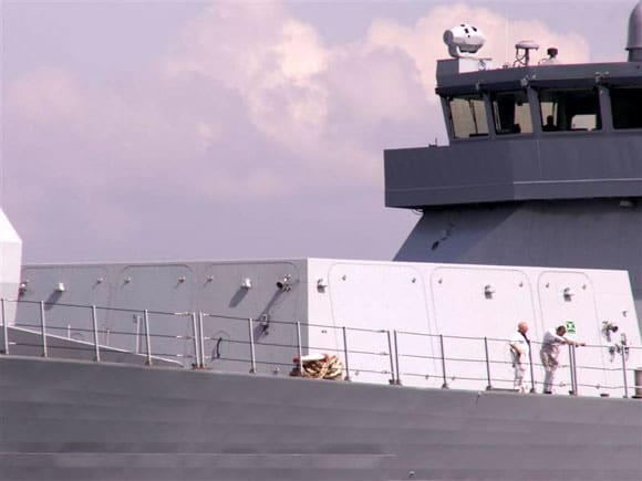
Thanks to the camera of Alan Paxton, a number of detailed shots of H.M.S. Daring can be seen for the first time. Photo 7 shows the uncluttered bow area, with no cable holders, brake slips, hawse pipes – in fact nothing. Well not quite, all of the functional equipment used for anchor handling is actually below the deck, which of course is part of the design to help reduce the radar cross section.
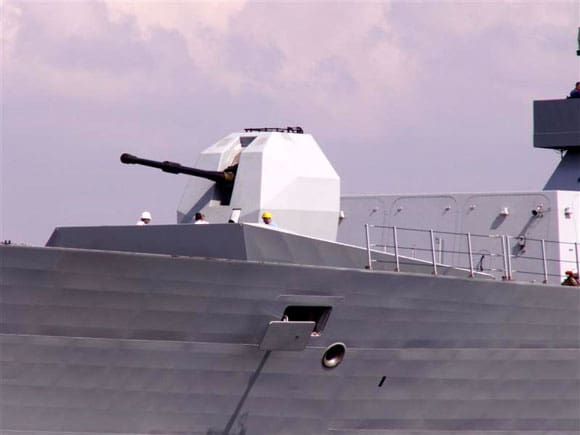
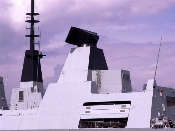
Even with the present generation of high precision ship launched SSMs (Surface to Surface Missiles) and their ability to do more than cause structural damage to any targeted warship, the inclusion of a naval gun remains an integral part of a balanced weapons fit and for this the 114mm Mk. 8 (mod 1) is the gun of choice. This may well change in years to come, when new weapons become available, but for the present the Mk.8 has been given a new radar reflective shield, seen here in Photo 8. Immediately abaft of the Mk.8 is the deck housing surround that supports 48 Sylver A50 launch cells housing the Aster 15 and Aster 30 missiles, Photo 9.
The Bridge and Sampson mast
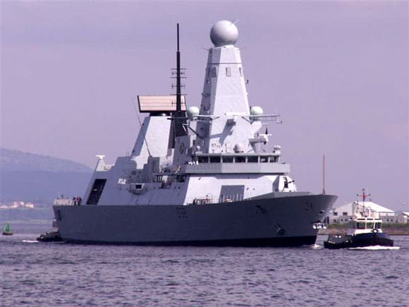
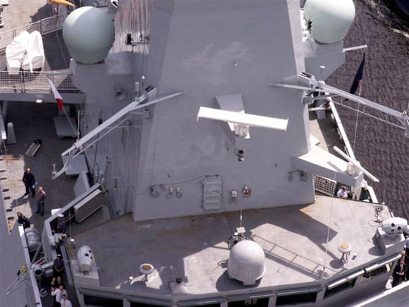
Interestingly the structural features around the bridge have more than just a passing similarity to those on the River class OPVs and once again follows the dictum of function follows form, in the interests of a low radar cross section, Photo 10. Moving towards the top of the bridge, in the centre of the photo and mounted on the forward face of the foremast is the Type 1008 navigation radar, Photo 11. The following pictures concentrate on the mainmast area, but particularly noticeable is the distinctive rotating sphere of the Sampson target tracking and illumination radar, Photos 12, 13, 14 and 15.
Amidships
Sited abaft of the foremast is the exhaust casing and within this is a dampening system, cooling exhaust gases to reduce the IR signature. There are few pictures showing in detail the top of the exhaust casing of any ship, but here is a clear unambiguous picture that will prove useful for future modelling purposes, Photo 16.
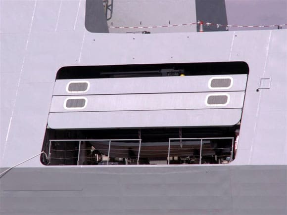
Going further aft is the deck housing (already shown in Photo 3) and on top of it is a communications and EW mast, Photo 17. Behind the communications mast is the pyramid shaped structure supporting the S1850M long-range search radar. This is at the top of Photo 18. Interestingly this radar, although being based on the Smart-L design, is actually more capable. In fact the specifications give the S1850M the ability to track ballistic missiles on launch and can thus it can be integrated into any TBMD (Theatre Ballistic Missile Defence) network. Equally the system is reputed to be capable of detecting up to 1000 air targets and identifying stealth targets and sea skimmers to a range of 400km, Photo 19. Moving to the base of the S1850M mast, there are a number of grills, which are visible in Photo 20. Another unusual and useful shot focuses on the top of the hanger and a clear view of the flight deck and its markings, Photo 21. Remaining within the area of the hanger, but viewing this part of the ship from the port elevation and showing the after exhaust uptake is Photo 22. Although a stealth configured vessel, the Type 45 still has to retain some form of ships boat and the enclosure for the RIB is recessed into the ships side. This has a shutter screen to make the opening flush with the outer superstructure, Photo 23. The next three pictures are concentrated towards the hanger and stern. Note that the hanger doors are in large sections, again configured to work like shutters, Photos 24 and 25. Note also that in Photo 25, there is a retractable panel in the after side of the hull.
That completes this brief detail look at the new Type 45 DDG and no doubt there will be much more said and more pictures will be available in the months to come.
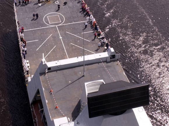
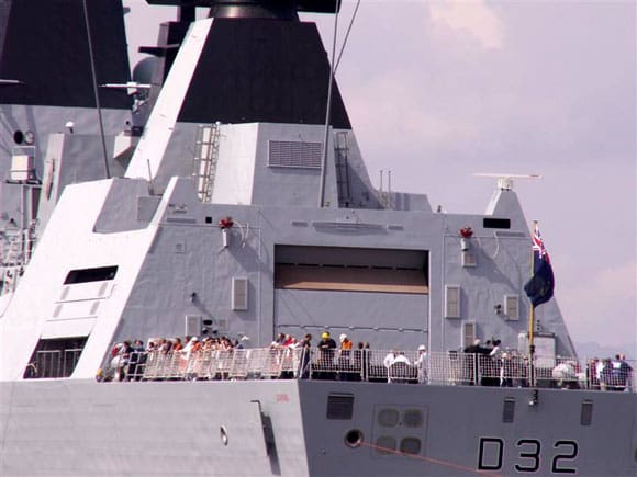
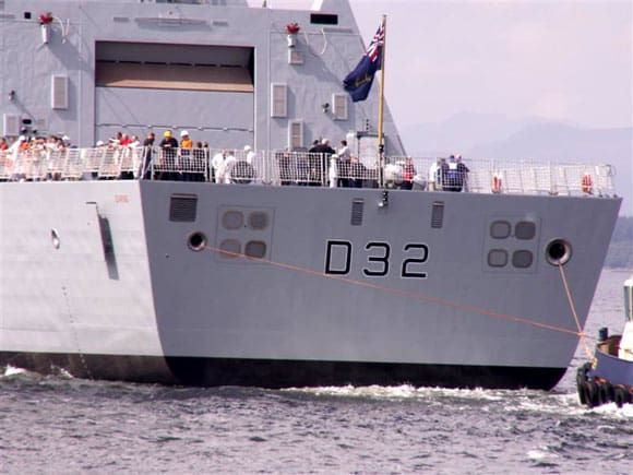
Pic 21: Top of the hanger and flight deck. Pic 22: Port side aft with the recessed RIB enclosure. Pic 23: Retractable shutter covers for the RIB enclosure. Pic 24: Looking forward towards the hanger. Note the clearly distinctive angled surfaces which provide much of the radar reflective features. Pic 25: Stern view with the covered opening for the deploying the towed linear array. Pic 26: Central lattice masts for supporting the Top Knot precision approach Radar. Pic 27: Each end of the lattice mast is in solid form being cut from 2mm styrene sheet. Pic 28: The basic island superstructure ready for fitting out. Pic 29: Each end of the lattice mast is cut to shape and ready to accept the tubular frame. Pic 30: Evergreen styrene rod provides sufficient strength when married to the solid ends.
Model hulls?
For those waiting with baited breath for either a semi-kit or a GRP hull, Im informed on good authority that PSShips/Sirmar will be releasing their 1:96 scale Type 45 as a full kit in March 2008, whilst Fleetscale will be also releasing their 1:72 scale version in the spring of 2008. Both I believe will include a moulded superstructure, but see advertisements and press releases for further information.
The building of the Aviation Cruiser Kiev Part five
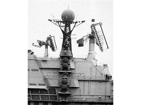
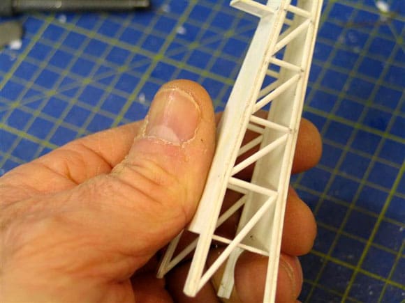
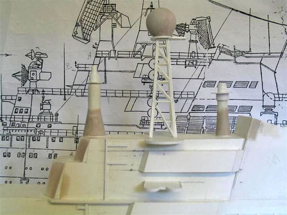
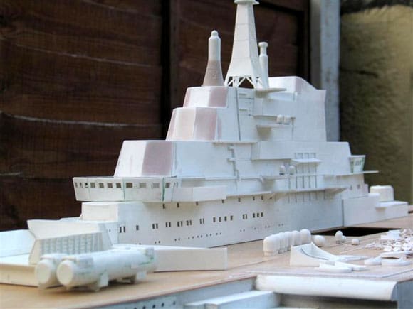
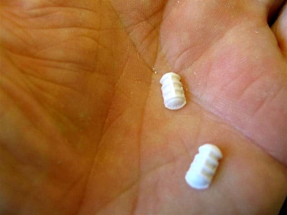
Continuing on from the ballasting trials, my attention shifted back to the superstructure. Preparations were made for the construction of the complex radar arrays that surmount the top of Kievs large island structure, Photo 26, and a brief change of tack to complete the task (or chore) of assembling 170 liferaft containers along with scratch building 170 support frames.
Top Knot lattice mast
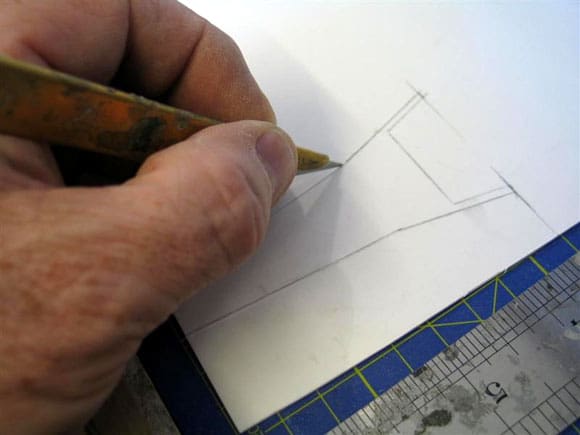
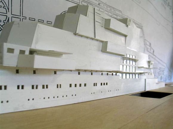
The main support mast for the Top Knot approach radar can be seen in the centre of the picture. This involved the building of the mast from a combination of Evergreen 1.5mm diameter styrene rod to form the lattice structure and the sides are formed from 1mm sheet styrene. As with much of the superstructure, the shape was lifted from the side elevation drawing using tracing paper, transferred to the styrene sheet and cut to shape as in Photo. 27. The basic superstructure is now ready to accept such assemblies as the lattice mast for Top Knot and the individual supports for Top Sail and Top Steer arrays (the latter two to be dealt with next month). Much of the external trunking, piping and cabling will be fitted as part of the on going development of this complex structure, Photo 28.
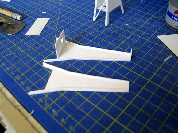
Brass tube was considered for the lattice assembly, but as each side was in effect a solid section, providing the rigid strength, although the entire structure is formed in styrene, I felt its durability would be more than adequate. 1.5mm diameter styrene rod is fitted to the outside ends of each 1mm thick profile with the separating base fitted into place. The two ends are now ready to be married up with the sides, Photos 29 and 30. The next step was to cut to size the twin semi-circular platforms for the Rum Tub ECM arrays, which are located on each side of the base of the mast. The mast can then be temporarily placed on top of the superstructure as in Photo 31.
At the head of the assembly is a circular platform supporting the large globe housing of the Top Knot array. The moulding of this dome to the correct circumference is to be discussed next month – for now, more of the smaller fittings. Also as a pre-requisite to painting, parts of the forward upper superstructure were faired in with a small amount of Isopon P38 fine filler which is my preferred choice. I also made a start on the trunking runs on the side elevations of the superstructure and a general tidying up of the joints, Photo 32.
Pic 31: Lattice mast temporarily in place. Pic 32: A start is made on preparing the basic superstructure for painting before many of the fittings are set in place. Pic 33: Moulded halves of the Side Globe antenna joined together. Pic 34: The base is prepared with a slight angle to suite the sloping sides of the superstructure. Pic 35: Cleaned up and now ready to paint. Pic 36: Sprue containing 18 liferaft containers. Pic 37: In all there are 170 liferaft containers. Note in the picture also the various stages of build for the container supports. Pic 38: Each liferaft half ready to be joined and cleaned up. Pic 39: Liferaft containers and supports temporarily in place. Pic 40: How the liferaft containers and the supports should appear when completed.
Side Globe ECM
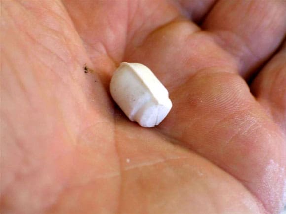
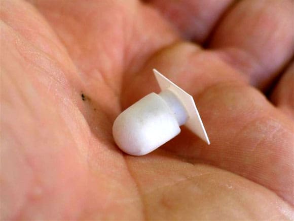
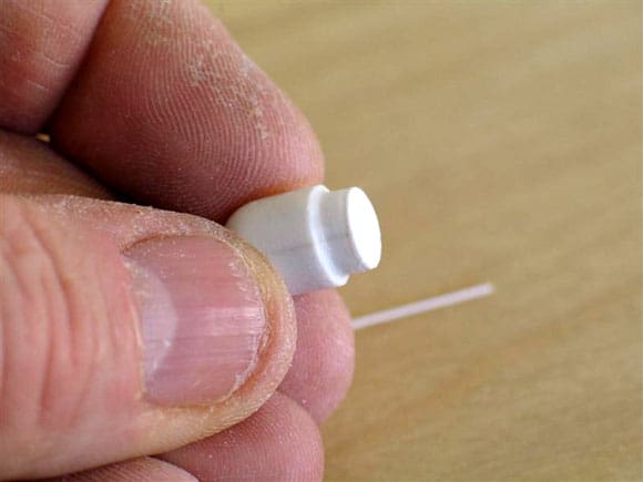
These can be seen in Photo 26 and they are large ECM (Electronic Counter Measure) domes fitted to the side of the superstructure, one above the other. Thankfully these formed part of the original kit and as such were moulded in plastic, but in two halves. All that was required was to join the two halves together as in Photo 33. The edges of the joint needed tidying up, but otherwise all was ok. I cut a small section of 1mm styrene and fitted it to the base, Photo 34. This was then trimmed to conform to the round of the base, Photo 35. These were set aside as one job less to do and could await painting.
Liferaft containers and supports
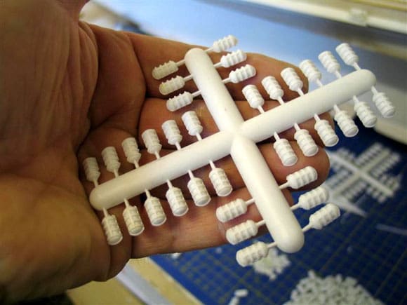
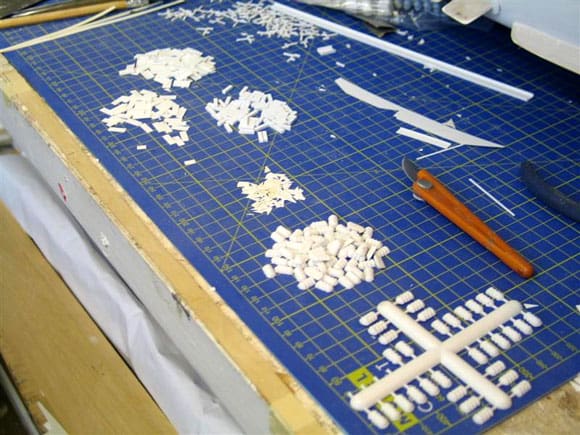
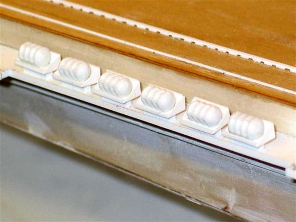
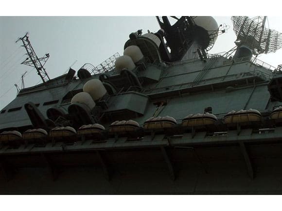
Unlike the Side Globe arrays, which numbered a mere eight, the liferaft containers and supports number a total of 170! These came on simple sprues and similar to the side globes, were in two halves, Photo 36. Some remedial work was required to ensure that the flat joining area was just that. Over a period of time each set was removed, cleaned and joined together. Photo 37 shows just how many were involved! Photo 38 is of a couple of completed liferafts. With each liferaft it was then necessary to make the support. Strangely these were not part of the kit, although making these from 0.50mm styrene did not present any major problems. Once manufacturing was underway, each support could be made up in minutes, probably faster and cheaper than moulding in resin or having a photo-etched set made,. The results can be seen in Photo 39 where a small number of combined liferaft containers and support racks were temporarily placed in position on the walkway. The mountings on the full-size Kiev can just be seen in Photo 40.
Next Month, I shall continue with the Top Sail and Top Steer radar arrays together with a simple method to make the exact size Top Knot sphere.
Answer to Mystery Picture in Model Boats December 2007
No stranger to these pages and the Mystery Picture slot is a reply from Patrick Moriarty. Ill let Patrick answer in his own words: An interesting picture this time. May I suggest that it is the Russian built ‘Petropavlovsk Class’ battleship ‘Poltava’. She was built at the New Admiralty Yard and launched in 1889 to be completed in November 1894. She was in Port Arthur at the start of the Russo/Japanese war and was badly hit in the Yellow Sea Battle on 10th August 1904. She limped back into Port Arthur and was caught there during the siege. After being hit by several 11in howitzer shells, she sank due to a magazine fire and was eventually raised by the Japanese. She served in the Japanese navy as the Tango until 1916 when they sold her back to Russia, who re-commissioned her as the Tchesma and stationed her in the White Sea. She was finally scrapped in 1923. The alternative is that your photo is of the Sevastopol, scuttled in 1905 some time after being mined and torpedoed, or is it Petropavlovsk which blew up after being mined in 1904? All three were at Port Arthur at the same time. Thanks Patrick and yes you are of course correct. The Mystery picture was indeed Poltava, so thanks for writing in.
Answer to February Mystery Picture – PC 572
Another difficult one to identify, but this class of submarine chasers as they were officially designated, was not originally intended as such, but were designed as minesweepers. PC572 was built at Albine Engine and Machine Works, Portland, Oregon between September 1941 and June 1942. Built of steel, the class were to be equipped with a single 3in/50 calibre gun forward and a single 40mm gun aft. Additionally PC572 embarked 3 x 20mm guns, two rocket launchers, depth charge projectiles and two depth charge racks.
Full load displacement was 450 tons in a hull measuring 174ft x 23ft and powered by diesels with two propeller shafts. She was capable of sustaining 20kts, enough to catch most submarines of the period.
PC 572 saw active service in both the North and South Pacific , primarily on convoy escort duties. Following the end of WWII and a brief period in Caribbean waters, PC572 returned to the US to be stationed at Norfolk, Virginia from 1949 to 1959. In February 1956, PC 572 was renamed USS Tooele and three years later was finally decommissioned. In October 1960, she was sold to serve in the Venezuelan Navy. The Mystery Picture returns next month.
References and acknowledgements
Type 45 Destroyer ref: Janes 2007-2008, Combat Fleets 15th edition 2008.
T45 machinery and electric drive Ref: www.theengineer.co.uk.
Kiev Aviation cruiser Ref: Soviet Warships, John Jordan.
USS Tooele Ref: www.navsource.org/archives/12/010572.htm.
US Warships of WWII, Paul H Silverman, page 252.
My sincere thanks to Alan Paxton and the Glasgow Warship Display Team for all their help in providing pictures of H.M.S. Daring.