Welcome! This month, firstly we are off to Beale Park for the Thames Boat Show. Yes I know it is not models, but the craft on display are of interest to modellers. Secondly, more on the conversion of Karoline to r/c and finally a bit about my Springer Tug.
The Beale Park Thames Boat Show
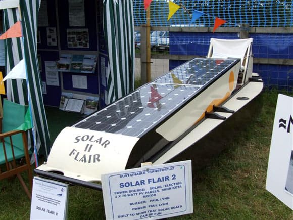
In June we visited the above event courtesy of Richard Howard of the Child Beale Trust. We have visited this event in the past and looked forward to a return visit. The show features boats suitable for use on the Thames and elsewhere, constructed from a variety of materials, both modern and traditional. Just inside the main entrance was evidence of the changes and development in boat building, notably this home built solar powered boat, Photo 1. The two solar panels generate 140 watts which then powers the 220 watt motor. The boat is 13ft 6ins long, with a beam of 3ft 9ins. Paul Lynn is the builder and as it says on the information board – ‘built to show that solar boats can be fun’.
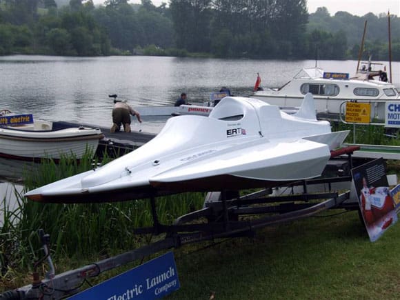
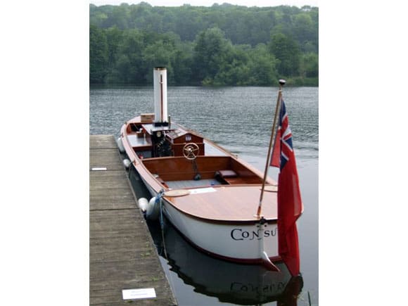
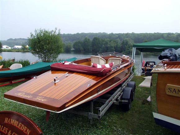
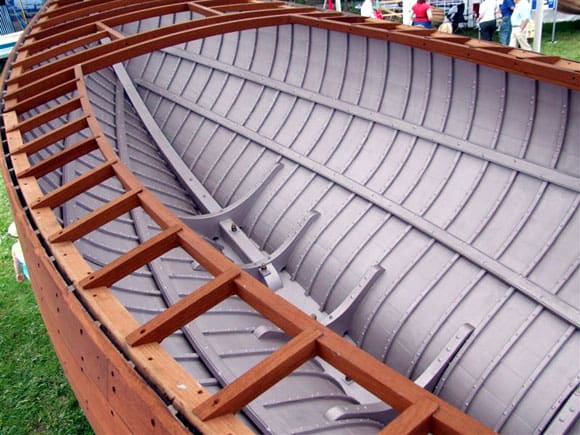
There was quite an array of electric powered boats, but only one of this design, Photo 2. This was to be the successor to ‘An Stradag’ – the first British holder of the World Electric Water Speed Record. As with An Stradag, which created the then fastest speed in 2005, this boat is to be piloted by Helen Loney. The boat is currently under development by the Electric Records Team. Further along the water’s edge was a more traditional vessel the Consuta, Photo 3. Built in 1898 as an umpire’s launch, the Consuta is 50ft long and is constructed from four layers of mahogany, stitched together with copper wire. Built by S.E. Saunders of Goring, this method of construction was patented by Sam Saunders. The steam plant uses a modern coal fired loco type boiler which drives the original twin cylinder engine of 6ins bore by 6 1/2ins stroke, which can develop100 h.p. Another classic was this slipper launch, Rosie Lee, with a stunning varnish finish, Photo 4. This was actually for sale, as were many boats at the show.
Enjoy more Model Boats Magazine reading.
Click here to subscribe & save.
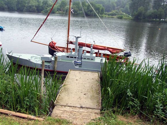
Something a bit different, which reminded me of the models that the Portsmouth Model Boat Club builds, was this offering from Kittiwake Boats, Photo 5. Offered from a range of three kits – King George V Battleship, H.M.S. Plymouth and a hunter killer submarine, this model is 23ft feet long with a beam of 3ft. It is built in three sections to assist transportation and storage and can carry a crew of two. The kits consist of 19mm, 10mm and 5mm ply cut to shape, a building manual, glue, screws, paint, 2hp electric motor and a 12v Leisure battery. Prices vary from the submarine at £1900 to the battleship at £2900.
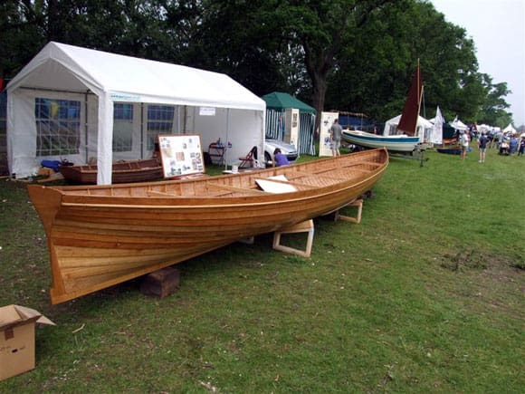
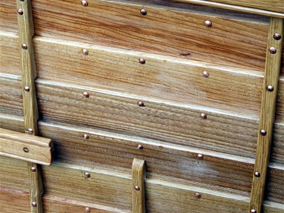
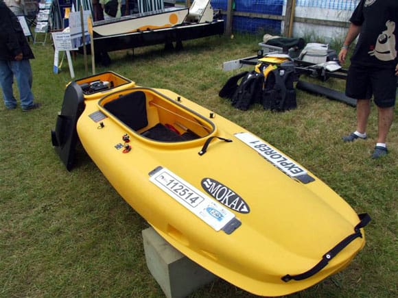
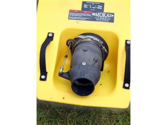
Returning to the subject of traditional boats, this six oared pilot gig is based on the lines of the Treffry, reputed to be the fastest gig to sail the waters off Cornwall, Photo 6. The original design, by William Peters, dates from 1838. Note the traditional clinker (clincher) construction, Photo 7. Now to go to the other extreme, this is a Mokai, Photo 8. Built from moulded polyethylene; the Mokai is 11ft 8ins long with a beam of 3ft. The design is quite unique, utilising a four stroke, six h.p. Honda engine in the stern compartment which drives a water jet, Photo 9. The gentleman demonstrating the boat claimed that it was possible to remove the engine in less than one minute. Seeing my cynical look, he promptly demonstrated this and he did prove his point! Quick release linkages everywhere and it was out in less than a minute. Later in the day I saw it in use by another visitor and his son on the lake.
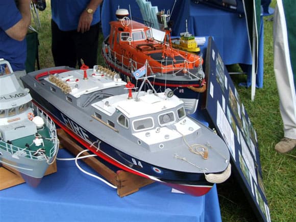
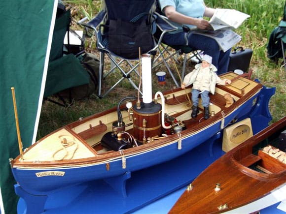
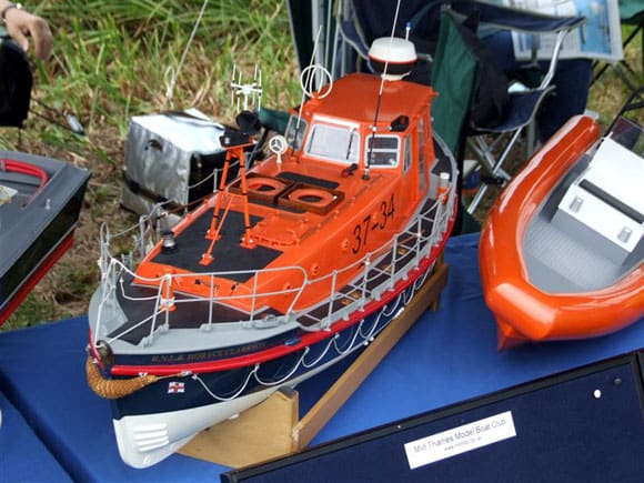
It’s been quite a while since we had the chance to see the Mid–Thames Model Boat Club at their home water. Their Gazebo was set up close to the edge of the water ,with a cross section of models from the Aerokits Crash Tender (or Firefloat Mk.2) to Thames Barges. Ian Hughes, the chairman, was in attendance with other club members. Rob Henry owned the Aerokits 46ins Crash Tender, Photo 10, and he was very enthusiastic about the model. Refurbished in 2005/6 since its original build in 1996, it was now equipped with twin Bullet motors, powered by 17 cells of 4000mA nicads! He is currently building a new version based on a hull from Waverley Models. This will be powered by two Graupner 820’s on 18 volts. Back to the traditional on the MTMBC stand and this steam model, Puffin Billy, was built by Brian Ashley, Photo 11. There was also a well made model of the Metcalf Mouldings Rother Class Lifeboat, by Richie Hale, Photo 12.
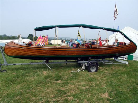
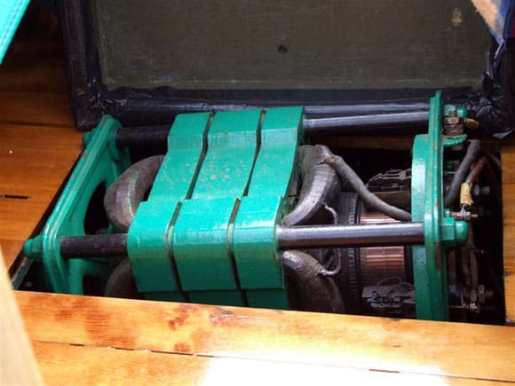
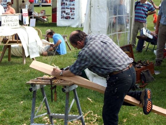
The unusual boat in Photo 13 attracted a lot of attention and it took some time before I could get a clear shot of it. It is an electric canoe called Gena and it was designed by the Ray Motor Company and built in 1903 by Tom Horsham and Son. It was purchased by current owner Robin Newlands in 1986 and restored. The fittings, engine and equipment are original except for the motor controller and soft furnishings and bearer boards. Photo 14 is of the drive motor with the copper commutator visible. It was good to see some of the old crafts still being practised. In Photo 15 an oar is being shaped by hand and in the background a coracle is being constructed. There were several organisations, colleges etc., demonstrating the older boatbuilding skills and these were being used in the construction of some of the boats on display. There were many being built from modern materials, fibreglass etc. and some from ply, but to see boats built like the pilot gig in the traditional way, was pleasing. This vessel in Photo 16, the Prima, was based on a 1937 design by Joan Jardine–Brown. The carvel hull is built from African mahogany over steamed oak frames by Simmons and Broome. Although I have visited this event before, it was pleasing to see such a cross section of different vessels utilising such a variety of skills. Thanks to Richard Howard for the invite.
Karoline Modifications – final part
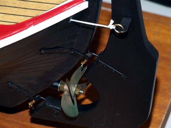
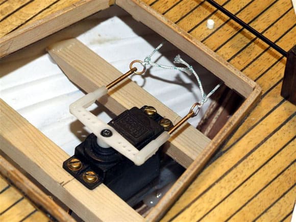
Following on from last month’s episode, I continued with the rudder linkage and fortunately I had in stock some parts from model aircraft servo connectors . These were the two threaded rods seen in Photo 17. These fitted onto the standard nylon servo connectors. As the threaded rod already had a hole drilled through, I fitted two of the brass rings I made last month. With the rudder in place, I fitted two rings through the brass plates in the stern of the model. I connected the rudder to the rudder servo with terylene cord, Photo 18. Incidentally, close inspection will show a small ring fitted through each of the rudder pintles to stop the rudder lifting out of the pivots. Photo 19 shows the connection at the servo end. The threaded rods help to adjust any unwanted slack in the linkage. The next stage was to install the radio and electronic speed controller (ESC), Photo 20.
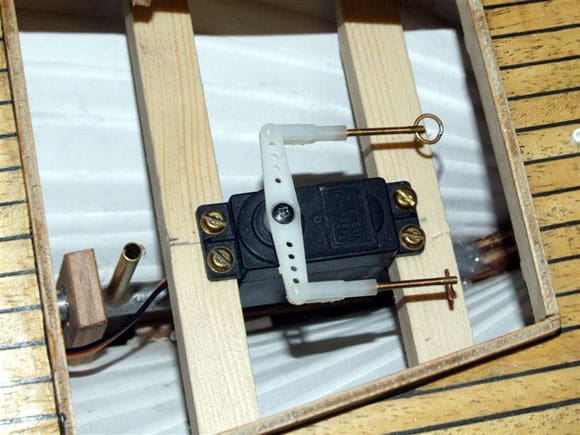
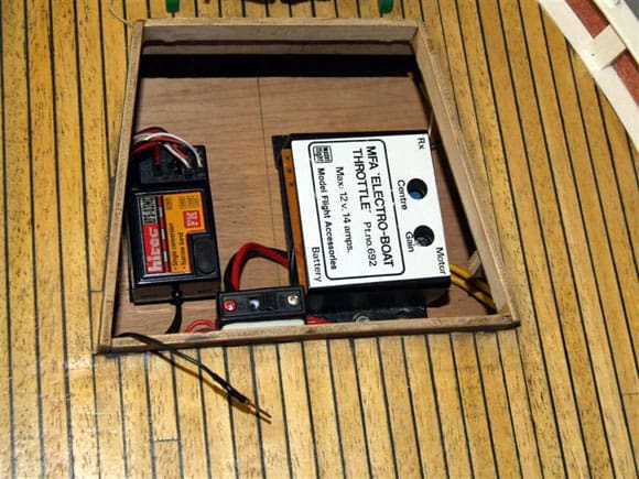
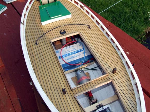
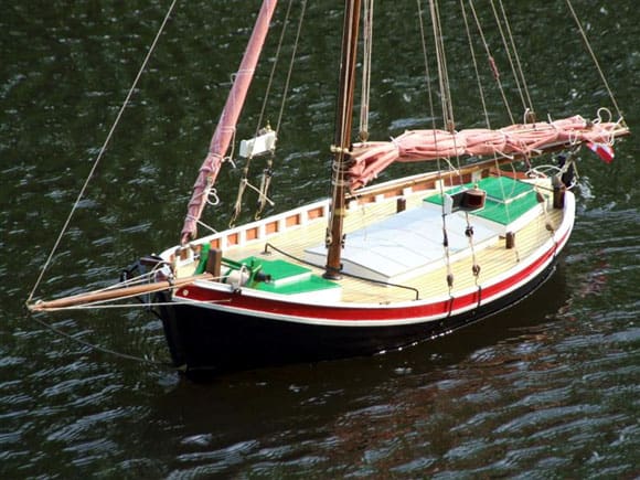
The radio is a Hitec 40 Meg FM three channel set with two channels used for rudder and throttle. The ESC dates from the 1980’s and still gives satisfactory performance. Note the on/off switch located at the top edge of the hatch coaming with the ‘red’ indicating the on position. Down at the lakeside I installed a 6v, 7.5 amp SLA battery into the battery tray I had made earlier, Photo 21. This fitted between the back of the motor and the mast step (tube). The battery, which also provided power to the receiver, was connected to the ESC. There was sufficient weight with this size of battery to float the model on its waterline. I had a look around the World Wide Web for motorised sailing vessels before I started this project, so I had a good idea how to rig the sails when the boat was under motor power. Photo 22 shows the end result. With her shallow draft, light plastic hull with no deep keel, Karoline blows to leeward in any breeze even without sails, so I don’t expect to win many navigation competitions. On the other hand it was a fun project, is fun to sail and that as they say, is what it’s all about!
Springer Tugs
Several years ago I built a couple of pusher tugs loosely based on the type seen on the American waterways. These tugs were intended for use in tug towing, or ship handling as it’s sometimes known. At the time this was quite popular at some of the clubs we used to visit. Eventually interest in this side of the hobby started to wane and the models were sold on. As with most things in our hobby, interest has been rekindled and there is now a need for two ship handling tugs!
I was browsing the World Wide Web for inspiration for a model to build and I came across what I was looking for on an American model forum at www.rcgroups.com/forums/index.php . I scrolled down to Boats–Dock Talk and selected Springer Class R/C Boats and found some 140+ pages of information on building and sailing these models. The first page of the American site has many photos of these models with a variety of superstructures. A plan for the model is also published complete with dimensions on the site. It appears that the model was designed by the Northwest R/C Ship Modellers as a competition boat, so all hulls, power source etc. are built to a common specification. If you fancy building one of these models I suggest you have a look at this website, but allow yourself plenty of time! Links to this website can also be found on some UK model boat web forums.
The first step of my build was to download and print the plans. Basically, the only plan required is of the hull profile as the bow and stern are flat, as is the hull bottom. I used the published guidelines for the dimensions, which stipulate a maximum length of 18ins (457mm), and a maximum beam of 8ins (203mm). The draft is determined by the hull profile from the plan.
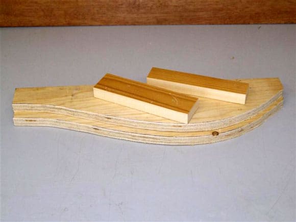
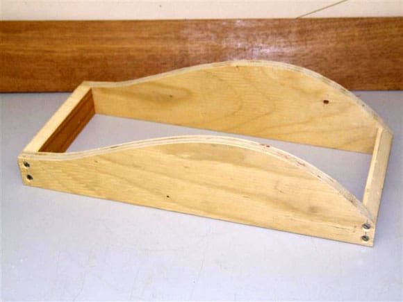
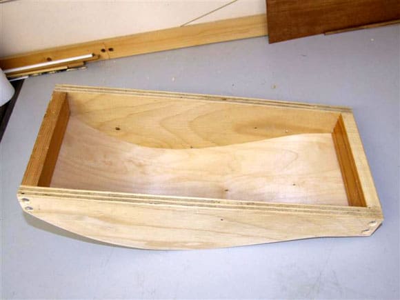
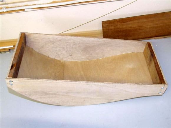
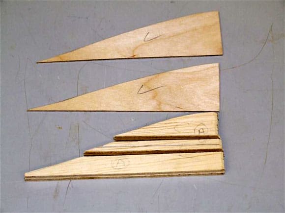
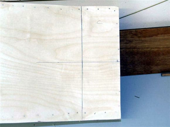
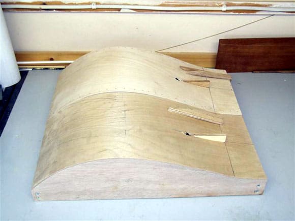
As I intended to build two models, I decided to use whatever materials I had to hand, or in other words, I was looking for a cheap build! The hull for the first model was to be built from wood taken from a plywood pallet, the second was to be built from 6mm ply. The hull bottoms for both would be 1/16th (1.5mm) marine ply. The bow and stern would be from whatever came to hand. The first picture, Photo 23, shows the two sides cut out from the pallet plywood, with the bow and stern cut from an old pine shelf. Photo 24 is of these parts glued and screwed together. (The screws were changed for brass later on.) Note the chamfer on the bow to allow the bottom skin to fit flush. I used PVA adhesive throughout, where the joints were wood to wood. Photo 25 shows the bottom skin in place. I did find this stage a bit difficult, so I had to use a variety of clamps and pins to hold it in place. This picture, Photo 26, is of the model built from 6mm ply. I did find this one mite difficult to build, as the sides tendered to flex when fitting the bottom. I also added reinforcement to the bow and stern to give the structure additional rigidity.
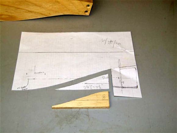
After allowing sufficient time for the glue to set, I traced the profile of the stern section of the hull to determine the best position for the propshaft, skeg and rudder. Photo 27 gives some idea of this process. Once the various locations were determined, the profile of the skeg was transferred onto a suitable piece of ply which was then cut out. The ply ‘cheeks’ to the same size were cut out from 1.5mm material. A section of wood equal to the size of the propshaft was removed from the skeg, Photo 28. With the hull already marked out, Photo 29, the first part of the skeg was glued in position onto the hull, Photo 30.
Well that’s all for this month. Next month I’ll carry on with the Springer build, plus my visit to ‘Wings and Wheels’ and Weymouth.