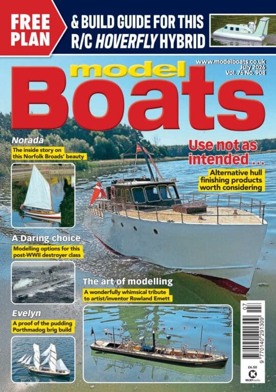

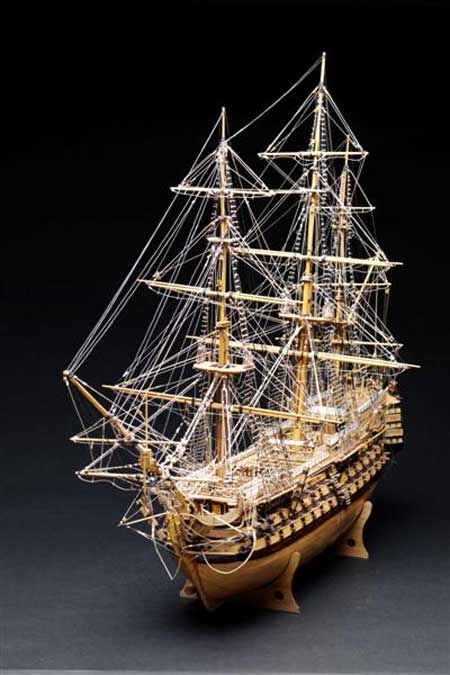
I decided in January 2002 to build a model of H.M.S. Victory. I started off by reading the manual and looking at the drawings in the kit I’d purchased to see what was involved in the construction. I then purchased and read a book ‘The Anatomy of Nelson’s Ships’ by C Nepean Longridge which I think is a must for any body constructing a ship from that period because the detail of how they build the ships is fantastic. I then decided that I would use the kit as the basis for the model and would include a lot of the features mentioned in the book.
I purchased some timber from HMS Victory to be included in the construction of the model to replace some of the kit parts. After aligning and fixing the bulkheads to the keel I fitted LED’s, hopefully to light up the model at night, choosing ones that looked like candlelight. I then proceeded to plank the sides of the hull, again using separate planking instead of one strip from stem to stern, and when finished sanded down to remove excess glue and give a smooth finish ready for varnishing.
The complete stern section was built by hand using only the drawings sizes from the model, and including windows which would allow light from the LED’s to show.
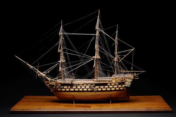
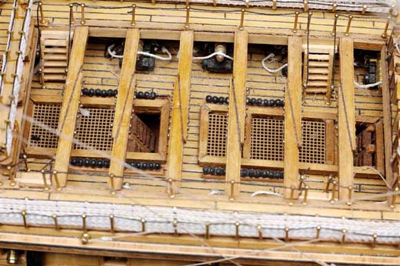
The next stage was the main decking which was to be planked with 0.5 x 3mm walnut strips cut to scale as the interior planks were. I decided to deviate from the manual once again by caulking between the planks, and after many practice runs I decided to use 0.50mm rigging thread. This part of the construction took quite a while to do so I either set myself a target of a certain number of planks per day, or broke the time up by stopping and doing something else for a while, then starting again – both methods help keep your mind focused on the decking.
Enjoy more Model Boats Magazine reading.
Click here to subscribe & save.
Once the decks had been planked and before fixing it in position I very gently glass-papered the decks down so as not to fluff up the caulking, to remove any excess glue and prepare the surface for polishing. When the smoothing down was finished I put the nail holes in the end of every plank – again I did this before fixing the deck in position. The polishing also took a long time but it not only looks good but protected the decks during the rest of the construction.
Masts and rigging
The first thing to do was sort out the different sizes of doweling, then cut the parts for each mast and keep them separate. I used my small lathe to glass-paper the masts and spars to the sizes required – this didn’t take long and then I was ready to start building up the finished masts. The lower part of the masts of the original ship were made of four or five different pieces. If you want to do this you could use four quarter round dowels glued together and then sanded down to the required size.
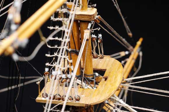
When making the tops (platforms on the mast) the thing to remember is the cross trees run athwartships (across from side to side) and the trestle trees run fore and aft (front to back). The cross tress are on top of the trestle trees. It sounds complicated but the drawing showed it in great detail. With most of the deck fittings in place I came to the rigging which can make or break the model. The first things to be fixed are the channels; to each side of the ship alongside each mast but slightly astern, attached with two pins into the hull as per the drawing to ensure a very secure fitting.
Once in place the next operation was to make the support brackets. The kit shows copper brackets but I decided to make my own, I made them out of 1.5mm square timber, mitred the edge pieces and fixed the cross piece. Once the channels were fixed I varnished them and touched up any damaged bits of varnish. It is best to do this on the deck parts because you will not have good access once the rigging is fixed.
Next were the chainplates. These consist of two deadeyes, wire strop, chain and fixing bolt. I used 2mm brass chain instead of the ones supplied with the kit.
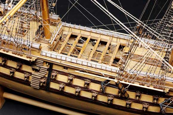
Standing and running rigging
The rigging of ships is divided into two categories, the standing and the running rigging. Standing rigging is concerned mainly with holding the masts and spars in position and giving them adequate support to enable them to withstand the varying strains to which they are constantly submitted. After being erected, standing rigging is permanent, except in the event of any part of it becoming slack, it can be tightened up for which provision is made.
Ropes used to alter the position of the spars and sails make the greater part of the running rigging. Most of the running rigging reeves or passes through one or more blocks, so that the pull of the rope can be led in the desired direction. The ropes comprising the running rigging are very seldom referred to as ropes – they are nearly always known as lines. The rigging of all ships up to about 1850 was made of some sort of vegetable fibre, hemp being generally used. Wire rope was not used at all in Nelson’s day.
The first items I made were the deadeyes for the shrouds, the shrouds being the ropes going up to secure the mast from the sides of the ship. The deadeyes are discs of wood, convex on both sides and grooved on the circumference. Each deadeye has three holes bored in it, through which the lanyard passes which lashes it to the other deadeye. I bought myself one of those ‘no hands’ devices and put a deadeye in each crocodile clip then lashed it properly. Once lashed I then touched the back of the lanyard with the smallest drop of glue to hold them in position because they have a habit of twisting and it’s hell of a job to get them right again.
When I’d completed all the deadeyes I made up the chains and joined them to the deadeyes and glued them into position on the chainplate, which I think gives you more control when fixing the shrouds.
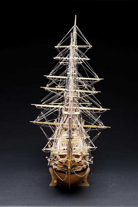
Now to make up the shrouds a lot of people use a jig but I find the following method easier. First cut a length of shroud line measuring from the port chainplate to the starboard chainplate via the height of the crosstrees on the mast with about 3ins spare on each side, then fold the shroud in half and make a loop just to fit over the mast and lash it. You can then loop it over the mast through the crosstrees down to the deadeyes on both sides, run the ends through the deadeyes and slightly tighten the shroud, holding it with a clip while you lash it.
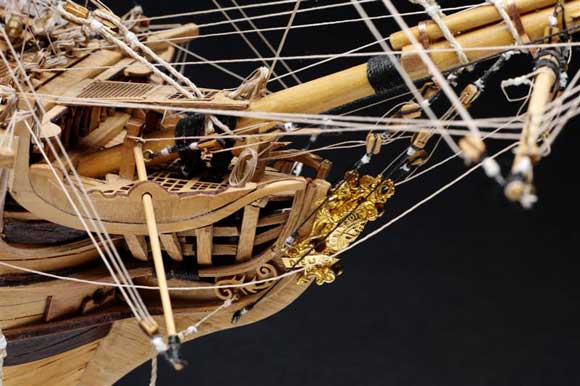
Having fixed all the lower shrouds I turned my attention to the bow before going any higher with the masts. The first job was to fix the gammoning rails and their supports. Again I didn’t use the kit parts but the timber that I acquired from the original HMS Victory which will enhance the model’s standing and value.
I started fixing the upper shrouds to the second series of masts; this again was a long job because this time I fixing the lanyards or climbing ropes to the shrouds, each one with a knot to each shroud. For instance on a lower main shroud there are 220 knots just to one lower side of one mast. Altogether on the lower shrouds there are 1084 knots. I used a clove hitch. So you can see why you need a lot of patience during this part of construction.
For the standing rigging I fixed the mainstays which are confined to the centre line of the ship and are set up on the foreside of the main masts they support. Before these could be started it was time to fit the bowsprit to allow fitting of the fore and mainstays. The latter is the largest and most important stay on the ship. Before fitting the bowsprit I fitted most of the belaying points and anchor points as possible as this saved a lot of time afterwards.
I carried on with the rest of the standing rigging, this again being a long task involving a lot of fixing of deadeyes and blocks. Once again patience was the name of the game. Having completed this I moved onto the running rigging, by which all the sails, yardarms, booms, etc., are moved into any position that is required to get the maximum out of the ship.
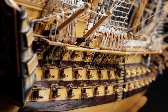
I used ‘black’ cordage for the standing rigging and ‘tan’ for the running rigging. Most of the latter reeves or passes through one or more blocks, so that the pull of the rope can be led in the desired directions. Again I used the rigging drawing from the book which shows the exact rigging used on the Victory when she was at sea, which again requires lots of patience. The running rigging consists of four different diameters of lines which were not all supplied in the kit, and with the different lines you also have different sized and shaped blocks. Once the rigging was complete I returned to the hull to fit the guns, lanterns and netting to the hammock racks.
The above gives some idea as to the complexity of the model which took three years to complete.