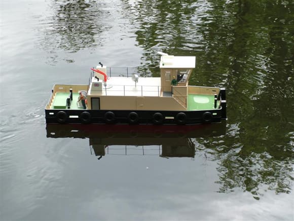
I was looking to find a kit for my next project but could not find a suitable subject. My club runs a tug towing event each year and I always miss out as I do not own a tug. This prompted me to consider a tug kit. I looked at the kits on the market and although I was impressed with the number available I wanted something simple that would not get broken during the rigors of a towing event. Whilst on a trip on the Rhine, I came across a number of pusher tugs. These looked very box like and might offer a relatively easy hull construction from sheet material.
On my return out came the pencil and paper (plus rubber), the plan was started. I wanted something that would easily fit into a car and not be too cumbersome to lug around. I ended up picking a scale of 1:24, which would hopefully meet the requirements.
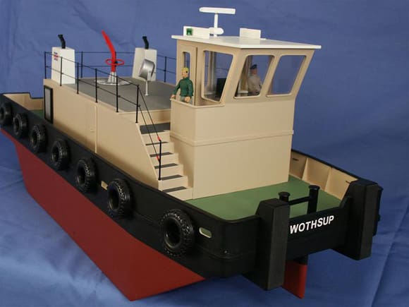
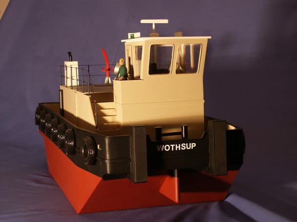
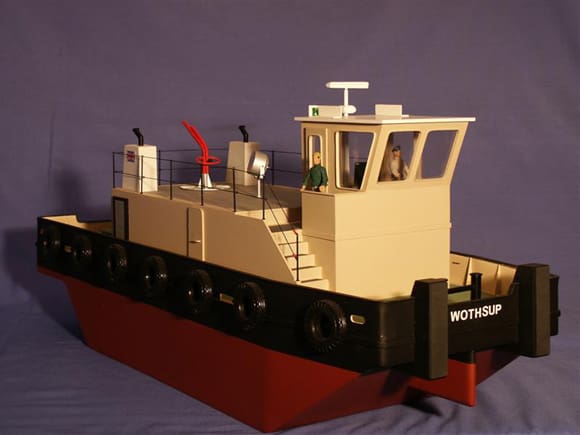
I ended up with hull size of 28ins length by 10ins wide and a depth of 5 1/2ins including the 1 1/2ins bulwark.
Materials
I began to make a list of the materials required. Starting with the hull I had to decide on wood or plastic. I had some sheet plastic (High Impact Polystyrene H.I.P) in my stock and thought I would try this as I had never used this material for a complete boat. For the hull and deck I would use 3mm sheet and the rest 2mm and 1mm. This is quite a cheap material, being about £7, £5 and £3 respectively for a 54ins by 26ins sheet. I buy the matt finish as this can be drawn on with a pencil easily.
Enjoy more Model Boats Magazine reading.
Click here to subscribe & save.
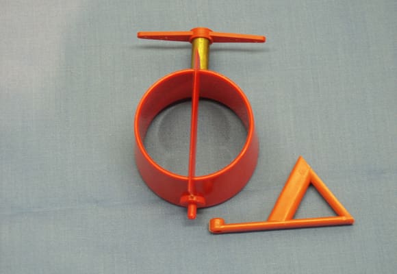
For the running gear I wanted a steerable Kort nozzle and found one from Robbe which is 50mm internal diameter at under £10.
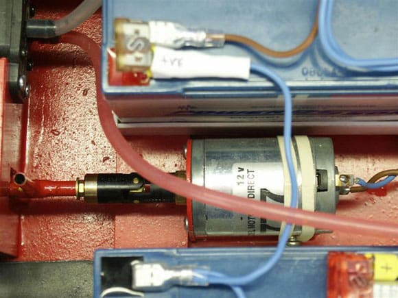
The propshaft came from my local model shop and is made from brass with bearings at each end with a 4mm thread. I contacted the Propshop, who were very helpful and a 4-blade propeller suitable for the nozzle was ordered. The next item to consider was the motor. A phone call to Model Motors Direct in Somerset put me on the right track and I ordered one of his 777 motors which will work on 6 – 12 volt and deliver a suitable power output. Well, that is the list of basic materials so let’s start on the construction.
Construction – Cutting the plastic
Cutting plastic is quite simple; score along the line with a heavy duty craft knife and steel ruler. Use only very gentle pressure for the first go, then go over the score again and again increasing the pressure until you have a deep score mark about half the thickness of the material. The plastic will then ‘snap’ along this line with just a little cleaning required later. Do not rush this or press too hard as the knife will slip and possible damage to you or the plastic will occur. Thin plastic can be cut right through. Three millimetre plastic is quite tough so be prepared to spend some time scoring it. Using a fine tooth saw is another method. I do have a small Proxxon table saw which I did find useful for cutting thin strips for the deck supports. The scoring method works well but just takes a little longer.
Bending the plastic
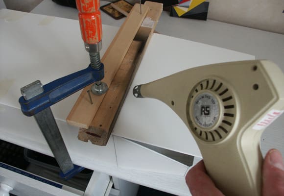
This is something that requires a little experimentation before tackling the real thing. You require a heat source to soften the plastic. I found a hairdryer not quite hot enough for this large area but I suppose that depends on the power of your dryer. An electric heat gun (paint stripper type) was very suitable. The heat has to be evenly distributed along the piece to be formed and this is easily done by gently moving the heat along the line. I found the plastic went from being soft to almost melting very quickly so great care is required for the distance and timing of the heat source. The best way is to hold the sheet over the edge of the bench and clamp a piece of suitably sized dowel or former along the line to be bent. When the plastic is hot enough you will see it start to sag. The heat is then removed and it can then be helped on its way with a flat piece of wood or something similar. Again only gentle pressure is required or the plastic can kink. Further heat can always be applied later if adjustments are required. Remember the plastic is quite cheap so if a mistake is made start again, I always find this saves time in the long run.
Making a start – The Hull
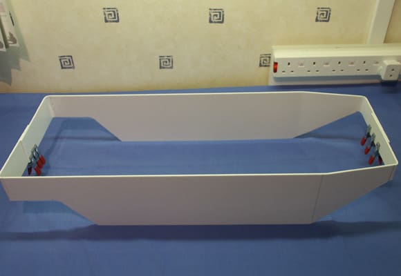
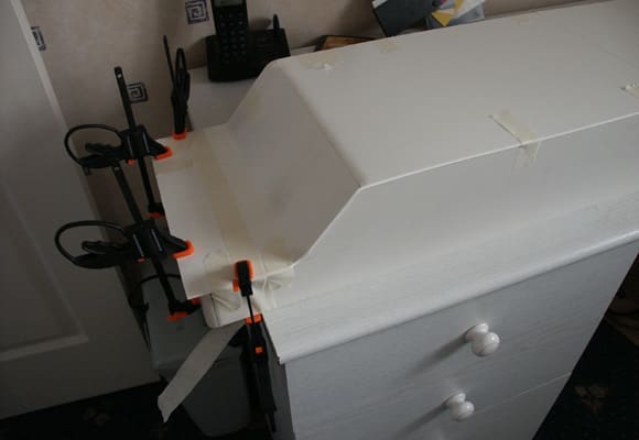
I made the basic hull from four pieces of plastic, two sides which when bent would form the bows and stern, the bottom and the deck. The measurements were drawn on the 3mm plastic sheet and cutting began. Because the sides are curved where it meets the bottom, the curve can be cut freehand or the waste taken out in sections with the curve filed to shape after. When the two sides had been cut I clamped them together and trimmed where necessary to ensure they were identical.
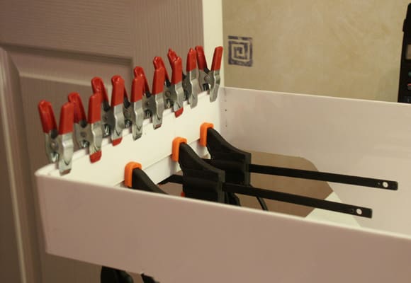
The two ends of each of the two sides were then bent around to form half of the bow and stern. These were made oversize and were trimmed to the required length, after checking for alignment when the two sides were placed together. A piece of plastic was glued with plastic adhesive (Precision Poly or Poly Weld) across the two halves with lots of clamps to hold it whilst it set. I like to leave something like this a couple of hours or overnight for the glue to really set.
The next task is to form the bottom. This is cut oversize and then placed on the upturned sides. I clamped a piece of wood across the bend and heated the plastic until it started to soften and moulded to the shape of the sides. This is slightly tricky as there is another curve to negotiate in the opposite direction. Go as far as you can and then start to mould the second curve, leaving the original clamps in place. When you are close to getting the second curve finished both can be heated at the same time and then moulded in position using a piece of dowel or wood.
When this has been completed for the bows and stern, mark a line along the join. The bottom can then be removed and trimmed to near the line. Any surplus will be sanded flush after the bottom has been glued in place. The side edges are then coated with glue and the bottom placed in position with clamps or tape to eliminate movement and make a tight join. When this was set I cut 5mm strips of 3mm plastic and moulded them to the shape of the inside bottom and side joint. They were then liberally coated with adhesive and put in place. This will reinforce the joint.
The top of the hull was checked for alignment and trimmed as necessary. Further strips were moulded around the hull sides which when glued in place would form the support for the deck. These were glued in place a fraction over 3mm from the top edge, i.e. the thickness of the deck.
The hull was placed upside down on a sheet of 3mm plastic and the hull drawn around onto the sheet. Check the sides are straight and do not curve in or out and then draw another line inside this one the thickness of the hull. Draw on the hatch and superstructure access holes. These can now be cut out. Try the deck for fit and adjust. Any gaps can be filled later using car body filler, Isopon P38. Extra supports were made to go around this large cut-out, extending the front and back ones to the sides. I used a piece of 10mm square wood for this.
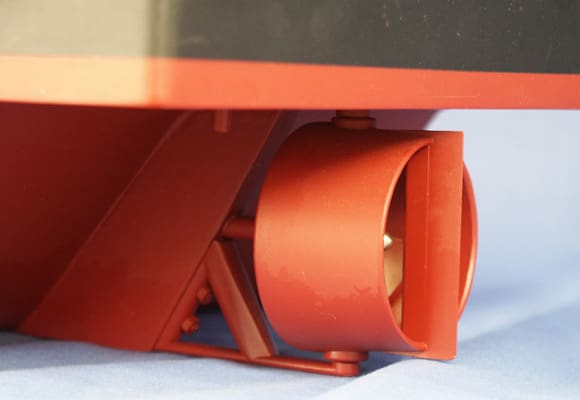
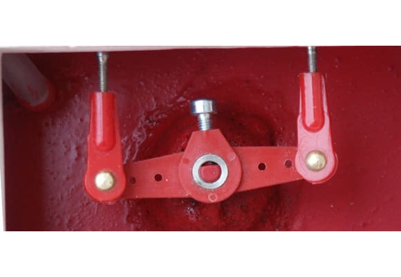
Before gluing the deck in place I fitted the Kort nozzle rudder. A hole was drilled for the rudder tube and with this in place I marked and drilled the hole for the propeller tube. A support was made inside the hull and the alignment of the shaft checked. This was then glued in position. A fin was then made from sheet plastic that would cover the tube and allow the lower rudder bracket to be fixed. Cardboard can be used to make templates for this. Once happy with the alignment the rudder and propeller tubes were permanently fixed with epoxy glue.
I also fitted a fin made from three layers of 3mm plastic to under the bows. This I hoped would aid manoeuvrability. Mounts for the rudder servo and motor were made and fixed in place. The linkages to the rudder were put in place and checked and the universal joint to the motor and tube also. With this now done and being certain it all worked correctly, the deck could be glued in position. The coamings for the superstructure and rudder hatch were cut and glued in position. When set any gaps on the hull structure were filled with P38 and sanded smooth.
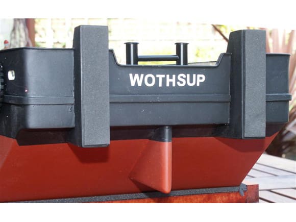
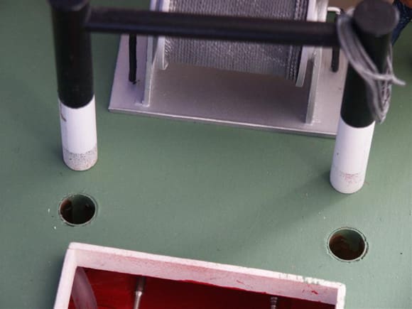
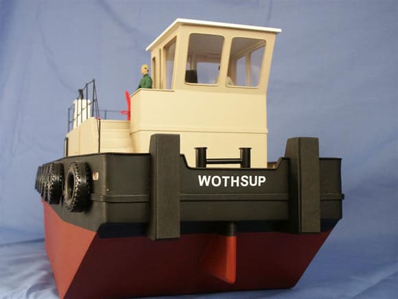
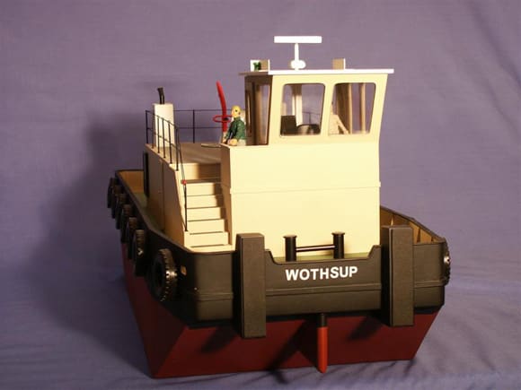
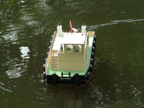
Two metal ‘H’ shape towing posts were made using 10mm and 7mm brass tube at the stern and 9mm and 5mm at the bows. The larger sizes were drilled and the smaller sizes pushed in the hole before soldering together. The next size up brass tube was used to make a socket in the deck that the posts would slide into. The sockets went through the deck and were fixed to the hull bottom with drilled blocks of wood. This would give strength and spread the load.
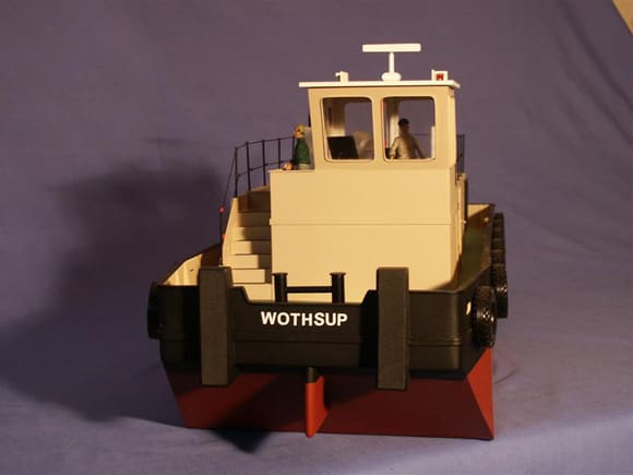
The next task was to make the Pusher Posts on the bows. Again cardboard templates were made. These have to be strong so I reinforced them inside making box sections with layers of plastic. The two structures were glued in position and any gaps filled and sanded.
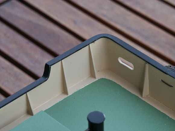
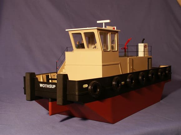
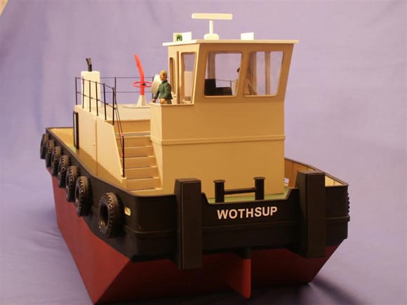
With this completed the final part was the construction of the bulwarks. I used 1mm thick plastic for this; one piece between the posts at the bows and two other pieces curved and meeting at the centre of the stern. When I was happy with the fit I cut out the wash ports and curved the bows and stern so that any tow line could move freely. This was then glued to the deck. The supports were cut from 1mm plastic and glued in position spaced evenly along the length. The capping was cut from 1mm sheet in sections to take account of the angles and glued to the bulwarks. The joins were filled and sanded after. On reflection I could have initially increased the height of the sides, which would then have incorporated the bulwarks. This would have made them stronger as they would have then been an integral part of the hull.
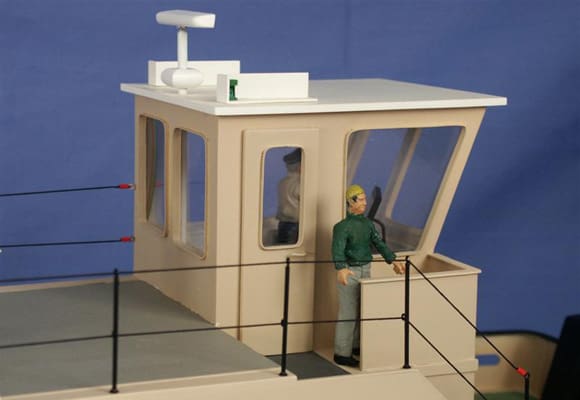
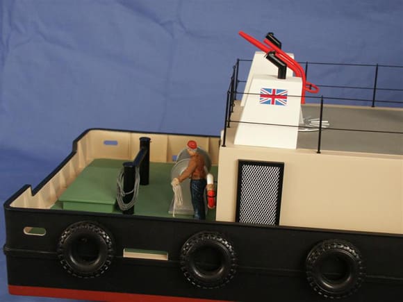
Superstructure
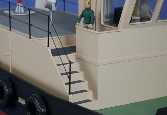
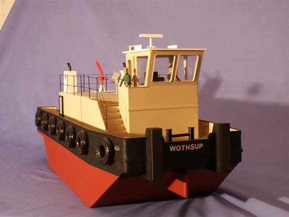
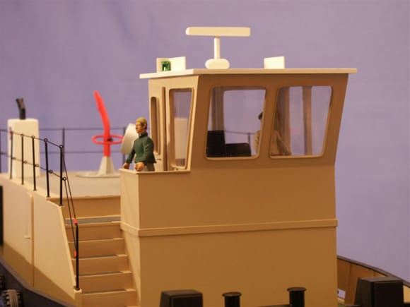
The superstructure is basically a box shape with an angled front to the wheel house. The sides are cut from 2mm plastic but the deck and wheel house roof were made from 3mm to give added strength. I included steps to the starboard side to add a little interest. The construction follows my previous methods but this time there is no bending required. Reinforcing strips were placed at the corners and joins to add rigidity and strength. I glued thin strips of plastic around the windows to give them some depth and glazed them with clear plastic after painting was completed.
Fittings
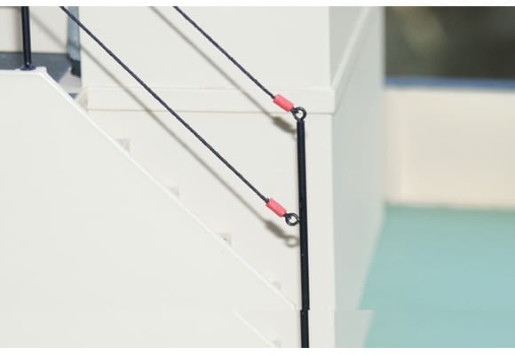
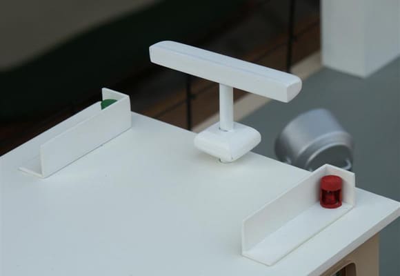
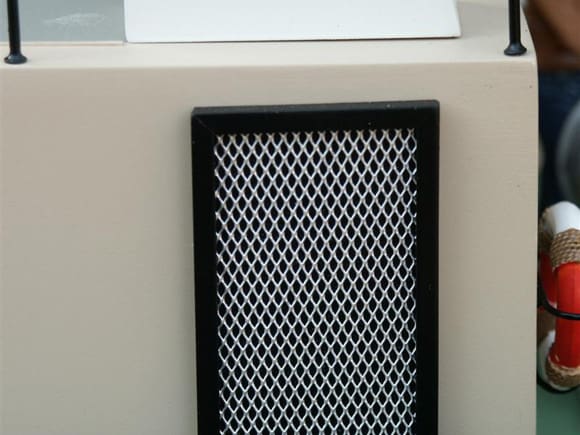
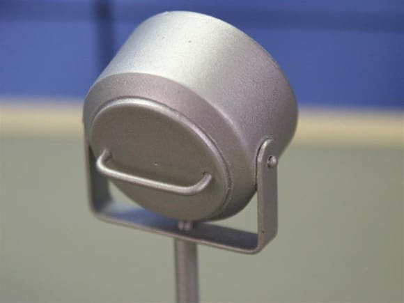
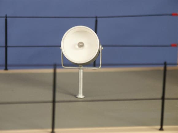
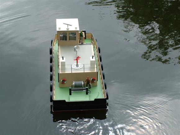
The funnels were made from plastic sheet and the exhaust from brass tube soldered at an angle. These were screwed to the deck with small self-tapping screws. Railing was made from 1.5mm tube with thin wire soldered to the top and centre to provide a fixing for the rope and a small washer for the foot. The ventilation grills on the sides were made from expanded metal (used for car body repairs) framed with angled plastic. Navigation lights were made from plastic card, brass tube and a red and green L.E.D. The search light utilised a plastic conduit fitting, purchased from B&Q, brass tube, wire and a white L.E.D. The radar rotates. I used an old servo with the electronics removed and screwed a threaded linkage rod into the top. This was passed through a suitably sized brass tube and the radar scanner glued to the top.
The cabin interior was fitted out with a table, chair, controls, V.D.U and maps cut out from adverts in motor boat magazines.
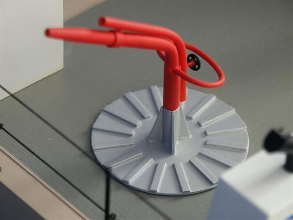
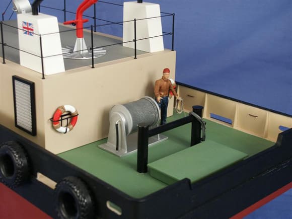
The fire hydrant was again made from brass tube, wire and 1mm plastic sheet. I did however make this work using a small 12 Volt pump. The inlet is in the stern by the side of the nozzle. Silicone tube connects the pump and hydrant to this. The winch used some plastic pipe and plastic sheet. Cord was wound around the drum to simulate the rope. The crew are 1:24 scale figures from the Dean’s Marine range. Further detail can be added to give that ‘working’ look; it is amazing what detail can be made from bits and pieces found in the scrap box.
Painting
All the structures were primed with Halfords acrylic spray paints. White was used for the superstructure and red for the hull. Humbrol matt paint was mixed 50:50 with white spirit and sprayed with an air brush to give the final finish. Halfords paint could be used for this but most of their finishes are gloss. Some very useful tips on painting have been published in Focus on Scale in the past and are well worth reading.
Final fitting and running
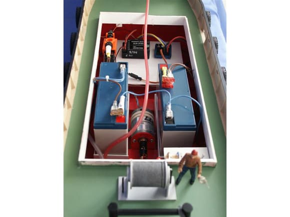
The final weight is around 6kg so I used two 6 Volt 10 amp SLA batteries. One 6 Volt battery will drive the motor and the other the lights, etc. Connecting them in series gave me the 12 Volts required for the pump. The two gave me a good helping of ballast so less added weight was required. The batteries were mounted in plastic trays which in turn were screwed to wooden battens glued to the hull bottom. These will spread the weight across the hull bottom.
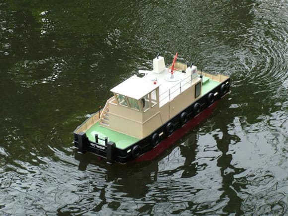
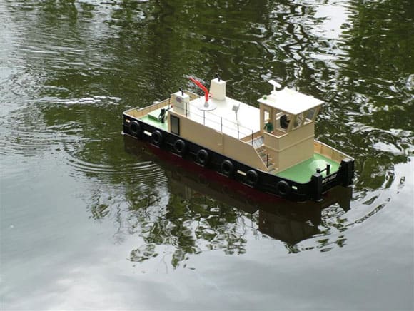
The tug was taken to the lake and trials began. I was delighted with the results. She had plenty of power and for such a boxy hull manoeuvred well, responding to the controls both forward and astern.
Well, I hope this article has given you some food for thought. It was not meant to be detailed plans or construction details but something that you might use as basis for your own design. The costs can be minimal depending on the detail added and the size of your ‘Odd Bits’ box. Happy boating!
Useful list of suppliers
Model Motors Direct ; 01749 860111.
Saffron Plastics Ltd (Basildon, Essex); 01268 288874
Squires Models & Craft Tools; 01243 842424.