Revells Queen Mary
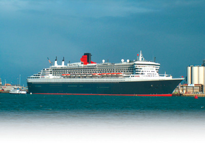
Queen Mary 2December 31st, midnight 2003, and a familiar sound was heard across Southampton – the Queen Marys fog horn. This same note had not been heard since 1968 when the old Queen Mary sailed for America for the last time – I was there then. Traditionally at midnight on December 31st in Southampton all ships sound their sirens to herald in the new year, and of course the old Queens were the loudest. The people of Southampton have always taken the large ships to their hearts, especially the Mary and Lizzy, but in the late 1960s they lost both Queens to be replaced with the smaller QE2, the only ship with a car registration plate for a name. Enjoy more Model Boats Magazine reading. Click here to subscribe & save. The days of Southampton as a passenger port were dying until the year 2000 when cruising came back to popularity with even bigger ships. Cunard decided to join in and ordered the biggest ship ever, the 150,000 ton Queen Mary 2 which arrived in Southampton on Boxing Day 2003 in atrocious weather – although half the city still turned out to welcome her. Early in January was the maiden voyage and thousands of people lined the Town Quay and Mayflower Park on a freezing cold evening to wave good luck to the ship, and they were rewarded with a super firework display. One big difference to the old Queens was the new ships ability to manoeuvre around the port without the aid of tugs, achieved with three bow thrusters, and at the stern she has four Azzy pods to direct the thrust. My thoughts that night were, Wouldnt she make a super model/. But these thoughts lay dormant until I found out Revell were bringing out a construction kit, and to make matters even better it would be a huge 870mm long one, big enough for motorising with radio control. Plastic Magic! Pic 1: The full size Queen Mary in Southampton in January 2004 before the maiden voyage. Pic 2: The funnel section of the full size Queen Mary. Pic 3: The bridge section of the full size Queen Mary. Pic 4: The firework display as the Queen Mary leaves on the maiden voyage. In the boxRay Rimell appraised the new kit in Purely Plastics and gave it a good right up, then sent the box on to me for assembly. It arrived and I quickly got out the instructions. There are about four pages of multi language general notes and a colour guide, and the rest of the assembly is pictorial. This rather threw me as Im not used to this type of instruction information, but by reading through each page all seemed to become clear. In the end, by selecting each page in order of assembly and keeping to the suggested program, the instructions have worked out well. The contents of the box were then inspected which consisted of the two large mouldings for the two sides of the hull and the rest of the parts were on sprues, mainly white, but some were of clear plastic. The sprues are all numbered and there is a helpful drawing sheet with each sprue showing the various individual parts with clear numbers. First thoughtsThe instructions cover the assembly for a static model and as I intended to motorise mine I first checked out the propellers and realised the scale ones provided would not be suitable on their Azzy pods. I decided to use two standard prop shafts and two small metal rudders. I bought two small 4 volt electric motors and two of the smallest RadioActive cheap shaft /prop units. The props were too big in diameter so I trimmed the blades back with a pair of scissors to 20mm diameter which fits under the hull nicely. The shaft tubes were too long so I cut them back to 100mm long and reinserted the plastic bearings. |
|
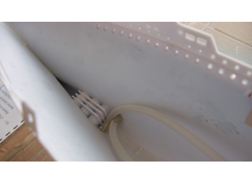
Pic 5: The bow thrusters water tubes and the false bow thrusters. Pic 6: The stern tubes glued in place. Pic 7: The bridge front during construction. Pic 8: The motors couplings and shafts. Pic 9: The silicone pipes to the bow thrusters. Pic 10: The aft decks and swimming pools. The build commencesThe two halves of the hull were glued together and the joints sealed with a little mixture, this is made by placing some off-cuts of styrene (Plasticard) in a jar and pouring over some liquid styrene glue, the off-cuts melt and form a paintable sealer. The four stabilisers were then glued in and sealed, I have them in the retracted position for safety as I could see them getting broken off in the water. The three bow thrusters units have to be assembled with the hull and these were glued in place and sealed with mixture. The four holes for the engine pods were not required so they were plugged with cut-off sprue and sealed. The hull was then put in the garden pond and checked for leaks and ballasted with spare weights to the water-line . The total displacement was noted as 2lbs 8 oz. I decided then to fit the shafts and the positions were marked on the hull bottom and two slots were chain drilled 6mm wide, I used one of those file drills bought at the MEE to turn the chain drilling to a slot. The prop shafts were laid in position and some 6mm wide strips of styrene 1mm thick were glued vertically either side of the shafts. The shafts were checked for correct position making sure the propellers cleared the hull bottom. A strip of masking tape was put under the hull and shaft on the outside of the hull bottom to contain the glue. Some 5-minute Araldite was mixed up and poured over the shaft tubes between the 6mm strips and this filled the box sealing the tubes to the hull neatly. For the rudders I cut pieces of thin brass 18mm square and silver soldered on a 3mm brass shaft 25mm long. I cut off an 18mm long brass tube 3mm internal diameter for the rudder shafts to turn in. The hull was drilled to take the brass tubes and a couple of pieces of styrene were glued on top of the holes for extra strength and the brass tubes were Superglued in. The rudder shafts were inserted in the tubes with a smear of grease and the tiller bars made from electrical connector and brass strips. The linkage back to the servo is 1.5mm brass wire. This propeller and rudder system is not to scale but I hope it will be robust and reliable. |
|
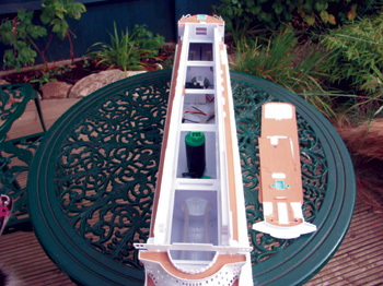
Pic 11: Looking down on the hull with the decks removed. Pic 12: Spraying the small fittings on the sprues. Pic 13: Some of the larger section over the drawing. Pic 14: The receiver batteries, 2 Action speed controllers and the 2 way switcher. Pic 15: The internal electrics and the cheapo transmitter. Bow thrustersI wanted to have working bow thrusters but all the commercial units were far too big. I had read about a car washer pump that would pump to two different directions by reversing the polarity. I found one of these pumps in Halfords, No. HWP21. The hull was drilled for 3mm brass tubes and one inserted each side of the hull near the bow thruster units, and two more tubes near the centre of the hull side for the water pick ups. The brass tubes were plumbed to the pump with silicone fuel tubing. The pump was mounted vertically in the centre of the hull so it would self prime. The propeller drive motors were mounted on a styrene plate with a blob of Araldite and connected to the shafts with a piece of silicone tubing. I made a couple of brass bushes to hold the silicone tube to the 2mm shafts. Early paintingOne instruction that surprised me was to paint the hull before continuing construction, so I masked up the inside and sprayed the complete outside with Halfords white plastic acrylic primer very lightly, then the upper sides were sprayed Appliance White. The top-sides were masked off and the underwater section with the props removed was sprayed red oxide primer and finally the top sides were sprayed Halfords Satin Black. I used the new BECC flexible masking tape for all the edges and this gave a very clean edge with no paint bleeding through. I fully recommend this product. I was somewhat dubious about painting all the plastic parts before assembly but I did follow the instructions and sprayed the complete sprues both sides with a thin coat of primer then a thin coat of Appliance White. The larger parts were laid out and sprayed as a group. I hand painted all the decks before assembly. One thing learnt was to trim off any small nibs where the cutter had removed the parts from the sprues for a good fit. AssemblyFinally I got round to the assembly; the parts all fitted exactly and most clipped into position. I then applied a little liquid styrene glue with a small paint brush. The glue seemed to go into the joints very well and caused no damage to the paint surface, probably the glue melted the paint and then it re-hardened. The windows in the superstructure are holes and would leak water if the model leaned over so I sealed the window holes with a strip of clear Sellotape on the inner side. I found it best to follow the build sequence to the book because when I missed a couple of parts they were awkward to fit later. The two top deck sections were not glued in place so that they could be lifted off for access to the inside of the hull. I glued a couple of 1mm strips of styrene under the rear top deck for location. The lifeboats and their davits were all painted and assembled off the model. I found the davits very weak, OK for a static model but vulnerable for a working model, so I used runny Superglue to fix the davits to the boat and hold the lifeboats to the davits. The ships swimming pools are moulded and have decals to indicate the water in them but I decided to fill my pools with clear resin that I think looks more realistic. ElectricsI obtained two of the very light weight Action 2 Amp Condor speed controller kits and assembled them. These kit are fairly easy to build but I recommend a good magnifying glass and a good quality 25 watt soldering iron. For the water pump bow thrusters I used an Action two way switcher. The radio control set is a four channel cheapo with an ultra light receiver bought over in Dortmund for 30 Euros. I have used a standard size servo for the rudders. The battery power is two packs of four AA cells at 2100mah . The rear four pack supplies the receiver and drive motors and the forward pack raises the voltage for the bow thrusters nominal 12 volts. |
|
TrialsI had reservations about stability and placed the assembled hull in the garden pond and loaded the batteries and speed controllers in position. The boat weighed 2 lb 5 oz plus 6 1/2 oz batteries – not stable but she sat on the water-line. I added lead sheet to the floor of the hull until the boat would sit and not roll on its side. This lead weighed 12 ozs and brought the hull 4mm below the water-line, I fixed a 12 oz flat lead under the centre of the hull with two small nuts and screws and Blue Tack to seal the holes. This has made the model stable in the water. The first pond trials were on the new Twyford pool home of the Eastleigh club. The water is sheltered and smooth and ideal for small scale boats. All went very well, the electrics worked correctly and the bow thrusters pump performed perfectly. I noted the bows sat lower than the stern so I would need to move some weight aft for the next outing. The only problem with the trials was the very dull October day and the photos did not come out too well. |
|
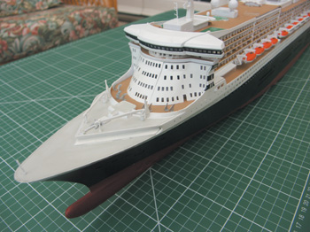
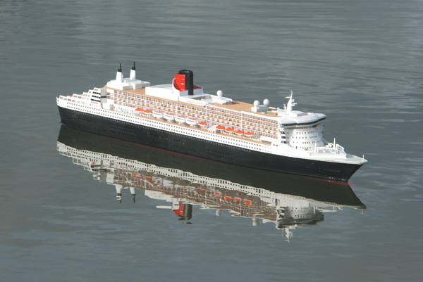
Final fittingsI had to stick on all the little fiddly bits like the hand rails and liferaft containers, some of which are very small. The bit I had most trouble with was the decals as they would keep sticking to my fingers rather than the model! ConclusionIn conclusion an absolutely super construction kit that will give many, very many, happy hours of build time. The kit makes up into a very accurate static model. The only slight criticism is the plastic hand rails which may be a little over thick and perhaps better replaced with etched brass ones. As a Plastic Magic RC model she looks good on the water and performs very well, I will use her on the demonstration pools at exhibitions and with the working bow thrusters she can manoeuvre just like the real boat without the need for tugs. The Action Condor 2 amp speed controllers and two-way switcher have worked faultlessly as well as the 5 channel cheapo radio. The final on the water photos were taken at Lakeside on a bright calm day; the model performed well and gained many nice comments from the public who do appreciate a good looking ship when they see one. |
A working model of Revell’s Queen
Enjoy more Model Boats Magazine reading every month. Click here to subscribe.
Article Tags:

