Marten, Howes and Baylis’ 1:24 scale kit
Amongst the quality kit makers Marten, Howes and Baylis must rank pretty high and I always look at their stand at trade shows. I was particularly impressed with a polyurethane casting of a clinker-built 23ft gig that Brian Marten showed me a couple of years ago. It was one of the small boats made for a larger kit model of the custom vessel Vigilant. He said they were going to produce a separate kit for the gig and I said I would have one when they did. Well it turned up in the spring and I have put it together as my entry into the 2005 Model Engineer Exhibition (ME), as my model of the French battleship Bouvet will not be ready in time. These notes should be read in conjunction with the instructions supplied with the kit if you intend to build this model.
|
|
|
Enjoy more Model Boats Magazine reading. Click here to subscribe & save.
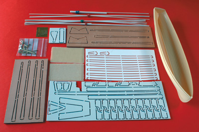
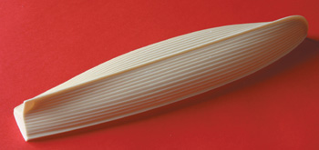
The kit comes with the casting as mentioned above, a lot of plastic strip of various sizes and sections, together with plastic grids and pre-cut pear-wood oars, Photo 1. Instructions with coloured pics also include details for finishing to represent wood, using scumble paints but I had already decided to colour-paint mine, as it was basically a plastic model anyway. The instructions said the casting was unfinished and to rub it down with 600 grit wet and dry used wet. I did not see the necessity for that but I ran a flat riffler file along each plank to ensure any bumps and lumps, likely on any casting, were removed. Photo 2. The only problem with the casting was at the bow and stern where the clinker planking should resolve itself into a flat planking to allow it to run into the dead wood at the stern and into the sternpost. This is done by a process called hemming (and various other names according to which shipwright you are talking to at the time) that enables the top plank to fit into the lower to produce the correct flat shape. The planks on the plug and hence the casting did not quite achieve this. At the stern I improved matters a little bit by using a pear-shaped burr but the front I left alone; there was a good chance of messing it up!
|
|
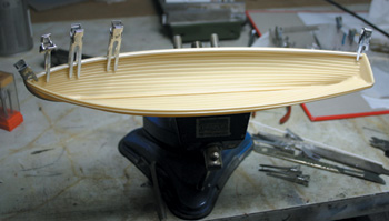
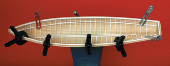
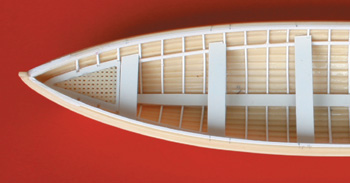
BuildingThe first step was to fit a 2mm x 1.5mm inwale all around the inside of the casting, Photo 3. This looks easy but it ain’t; it requires great care to make it conform to the profile of the gunwale. I used thin cyano adhesive throughout except where I state otherwise. I spent some time doing this and used plenty of clips to ensure the inwale ended up where I wanted and not where it wanted. Also make sure it is well secured as it will be subjected to a fair degree of stress when you spring in the timbers (ribs) later. Fitting the ribsAlong each side of the keel 1×1 strips 9mm long are fitted to space out the 1×1 ribs. The instructions tell you to fit all these spacers first but a better way, I think, is to fit the central pair of ribs first, as described in the instructions, and with these fitted use two 9mm spacers pieces (one each side of the keel) to space out the next pair of ribs and so on. This eliminates the need to space out the keel spacers with a 1mm gap between which you will not get right anyway. Just make sure you get the first pair of ribs absolutely correct and all the subsequent pairs parallel to them. Fitting ribs is a boring job but repays care. Just think of all those young apprentice lads drilling all the nail holes before the invention of small power tools! I would emphasise the need to get the first pair absolutely right before proceeding. Amidships rib fitting is fairly easy and is where the maximum length of rib occurs. Get one right and copy for the opposing rib. At the same time cut another rib the same length or slightly smaller being the first of the next pair and so on. This eliminates the need to measure every rib length. The length of the ribs becomes smaller the nearer you get to the extreme bow and stern. The amount of “shortness” amidships is very small but this increases toward bow and stern. The worst ribs to fit are those at the bow, which do not like having to twist to accommodate the run-in at the bow and will try to slip away from true. You will have to exert your influence here! At the stern you have a reflex curve which means holding down the inner ends of the ribs, Photo 4.
|
|
The RisersThe instructions talk about stringers here, which are the fore and aft members on which the thwarts, stern sheets and forward gratings sit. They give precise instructions as to the vertical distance below the gunwale at various points along the hull. Make sure these dimensions are adhered to; check several times before applying the adhesive. Trying to rearrange these after gluing would be a nightmare. Thwarts, Stern Sheets and Bow GratingThese all sit on the risers (stringers) and have to have notched ends (sides) to fit around the ribs. This is a problem, as it could become a source of scrap if you make a mistake. To avoid this I produced card templates first and having got them to fit perfectly I used these to produce the plastic parts. Make sure you get the thwart spacing right; I measured the full size drawing in the kit as no dimensions were given. The kit is supplied with two rectangles of cast polyurethane grids from which the two framed fore and aft grids have to be cut. The stern sheet floor grid has also to be cut from these two rectangles so do not waste any. The frames are pre-cut from plastic sheet and merely need to have their retaining tags cleaned up. I cut the pieces of grid using scissors and cleaned these up using my miniature disc sander. Just make sure, as the instructions say, to get the pattern of holes symmetrical and the grids a snug fit into their frames, Photo 5.
|
|
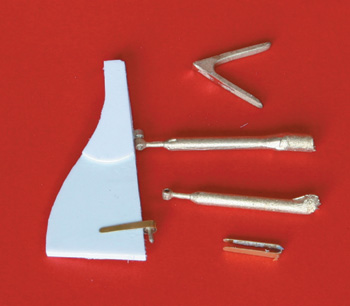
Rudder and FittingsPrecision cast brass pintles and gudgeons are provided together with a cast breast hook and two horizontal knees for the transom, Photo 6. These items require cutting from their sprues and cleaning up. I found the two rear knees required opening out slightly. If you do, hold them with two pairs of pliers and gently prise them apart. The exterior profile will need cleaning up again of course; ain’t life hard but it’s probably worse in the Legion so take heart. Fitting the pintles and gudgeons is straightforward but get the geometry right – re-check before drilling holes and cutting slots, etc. In the kit the two pintles are of the same length. If you have ever struggled trying to rig a rudder with your hands frozen you will know why one should be longer than the other. Trying to engage both pintles at the same time is enough to make a saint swear. In the north east some cobles have the lower pintle about five times longer than the upper.
|
|
PaintingAt this point with everything finished I sprayed on a coat of Halford’s white primer just as a rectification coat and basis for final colour. I opted not to go for a wood finish using scumble as described in the instructions but to get some colour into the scene. The basic colour being white with red and orange top sides, thwarts, etc. The same colour as my scratch-built model of a 32ft gig. After rectification i.e. removing excess glue, etc., the basic white was built up with several sprayed coats. Unfortunately I fitted the keelson, which sits on top of the keel, before painting same. This required exterior masking to paint it the same colour as the other footboards. This should have been sprayed before fitting when it would have been easy.
|
|
FootboardsThere are six of these, three each side of the keelson. They simply needed cleaning up and spraying. Fitting them required spacers, which I made from short lengths of 2mm diameter dowel. Various clamps were used to hold the boards in position, sitting on the ribs, whilst a syringe was used to flow the adhesive down each side under the board to secure it. There is no indication of the longitudinal position of the footboards given so I just hid their fore ends under the forward thwarts. Their rear ends should then be under the aft thwart where the stern sheets grating lies. Just play about here until you are satisfied that your assembly looks right. With the footboards and the rear foot grating secured the thwarts, forward grating, stern sheets and top stern grating can be fitted. Position these parts by measurement of the full-sized plan. In Photo 7 the pieces of paper tape are there to mark the position of the thwarts. The original instructions specify all components to be notched around the ribs at their transverse ends. This makes fitting very difficult. Some Cornish gig builders did not do this. The ends of the thwarts, etc., touched the ribs but were not notched to accommodate them. I think therefore you could dispense with notching if you feel lazy! Stretchers and KneesThese were by far the most fiddly bits on the model. The stretcher bar itself is simply a piece of rectangular plastic stock 1mm x 1.5mm. They are housed in notched square end supports that are fixed to the appropriate foot board. The drawing of these supports needs to be modified because the stretcher fits into the supports at an angle and therefore the depth of the housing slots needs to be at least 2mm. To get good clean slots I stuck two pieces of 1mm thick plastic together with double-sided tape and milled out the slots with a 1mm diameter slot drill. The outside shape was then cut relative to the pre-cut slots but I made 1mm larger in width and height. This was because the original size would have made very flimsy parts. By splitting them apart I had identical pairs of course. These can be seen in position but unpainted in Photo 7. These had to be sprayed red before final assembly. To do this I stuck pieces of masking tape to the appropriate footboard and then stuck the supports onto the tape with white glue. The stretcher itself was cyanoed into the slot making a sub-assembly, which could be removed for spraying. They were finally glued into position, after the tape had been removed of course. I fixed these assemblies a fixed distance from the aft edge of the adjacent thwart. Think about it!
|
|
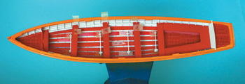
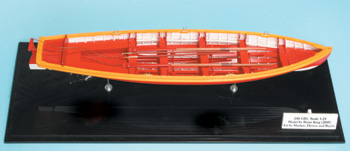
Vertical Knees at the end of the ThwartsAn adequate number of these are pre-cut for you. The “gunwale” end is made over-long for fitting purposes. Twenty of these have to be individually fitted – each is different, Photo 8. The two parallelogram strips shown on the drawing, which flank the stern sheets grid have to be cut from scrap. They simply lay on the ribs each side of the grid. I made another stern sheet seat back as I didn’t like the fit of the original part. FittingsI only made two oars for this model; no need to overdo things, is there? They are called oars but sweeps would be a better name. The blade has no real shape and like most sea oars is not “spooned” although those I made for the Scillonian Gig last year were. The position of the leather binding is not given on the drawing but I put mine 42mm from the handle end and made it 10mm long for the large 12ft oar (these distances were slightly reduced for the 11ft oar). If in doubt put the oar in the rowlock to show the band’s position. The reinforcing copper bands on the oar blades were not etched as some of the drawings may indicate but inked in with a metallic gel pen obtained from Tescos (no part number given). Photo 9 shows the completed model on the black acrylic base.
|
|
Comments on the KitWhether this kit is worth £65 to you is a personal decision. I think I certainly had my fun with it and it made a nice little model. My criticisms are minor. Firstly as long as you do not scrap anything there is adequate material. Most of the stock is standard material anyway and would be easily replaced. 4mm square sectioned plastic was supplied to make the centre support for the thwarts. It was suggested that these were stuck to the underside of the thwarts before finally fitting the thwarts. I decided to fit the thwarts first, measure the height required and turn off 1/8in diameter poly-tube instead. If you fill the tube with white glue and slide it into position gravity will allow the glue to fall down and secure the bottom end, which is standing on the keelson. A touch of runny cyano applied top and bottom will finally fix these securely. Do make sure, however, that they end up vertical! On fitting the five rowlocks I found one had an incomplete arm, which was a nuisance. I think with such delicate components a spare should be provided by the kit manufacturer. If the user requires a replacement it saves an awful lot of trouble if a spare is given otherwise a great deal of effort is required by all parties to acquire another one. On some of mine the locating shaft below the rowlock itself was bent and required straightening. Also its length was a bit mean. I held the rough sprue in my lathe and turned a bit more shaft – a tricky operation! I thought the rowlocks were the poorest part of the kit and could certainly be improved. I was not keen on the plastic grids supplied, they needed a fair amount of work to bring them up to standard, holes needed poking through, etc., and the strength of the unsupported ends produced by cutting through to produce the tapered shape was very suspect. I would have preferred brass etched grids. However, all in all, this is a fine kit. The main component, the cast hull, is superb. Any of you who have made polyurethane castings will know how difficult it is to produce bubble-free castings from this material. Apart from my previous comments the only fault, and that is minor, is that being a casting, the lower edge of the planking is rounded slightly and is not as crisp as it should be. There is no doubt the kit can produce an exhibition class model if care is taken. The Achilles heel is probably getting a clean waterline on a clinker built hull. Very careful marking out and masking is required here. Marten, Howes and Baylis are to be congratulated.
|
|
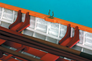
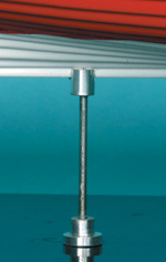
Comments on Casing the ModelAny decent model needs a case, as once dust has had its day it’s removal is difficult if not impossible; this is apart from physical damage. You could write a PhD thesis on cases: what to do and what not to do. In the past one has seen the most elaborate cases, making the case more interesting than the model, which is the wrong way round really. In my view the case should protect and project the model but be self-effacing. With smaller models it is probably best to use a completely transparent case, dispensing with any framing, which always gets in the eye-line and hides the model. Firms can now make acrylic cases where the front back and top are formed from one piece with inserted ends. This has been made possible by special machines that only heat a narrow strip of material thus allowing very tight folds. These cases are ideal for small models. The position of the model inside the case is all-important as is the way it is supported. The obvious way is to make two crutches and in fact two are supplied in the kit but I think they look clumsy. My model was supported on two 1.6mm diameter stainless steel rods as shown in Photo 10. The top of the rods ended in a 5mm diameter cylinder, which had a 1.8mm slot milled across it to house the keel. The lower end had a double diameter (washer), which sat on the base of the case. This was screwed into the rod with a 10BA thread. The rod also penetrated the base and was secured with a washer and a 10BA nut. The underside of the base was counter-bored to produce a smooth flat base. Do not attempt to case the model too closely as this always looks bad. The model must have an adequate airspace around it. The case being acrylic will have a static charge attracting the ever-present dust. To avoid this wipe with water that has had a few drops of washing-up liquid added. Avoid rubbing it dry, as this will simply charge up the plastic a gain. After the exhibition first remove the dust and then repeat the antistatic treatment. It is not too difficult, if you can cut glass accurately, to make the case from 2mm thick glass. Fix the sheets together with Glass Bond produced by Loctite, which sets under the action of UV light. You will need a simple fixture to hold the parts in the correct position while the adhesive sets. Marten, Howes & Baylis are at 216 Bredhurst Road, Wigmore, Gillingham, Kent ME8 0RD. Tel: 01634 233146. There is a website at Model Boats.co.uk
|
Marten, Howes and Baylis’ 1:24 scale kit
Enjoy more Model Boats Magazine reading every month. Click here to subscribe.
Article Tags:

