
A freelance Broads Cruiser by Ray Wood
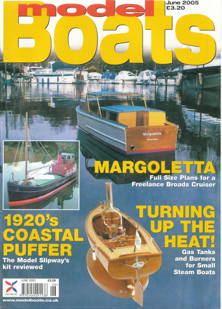
Editorial Note: Cabin cruisers are always an appealing modeling subject as they offer the opportunity for some miniature carpentry using traditional materials which makes a nice change from the combination of grp and styrene used in many kits. You can easily personalize them to your own tastes as well. Margoletta is just 24 inches (61cm) long which is a convenient size for a model of this type. This is a reproduction of Ray’s original article from 2005.
The name I have chosen for my first model boat design to be published originates from Arthur Ransome’s book Coot Club which was written just prior to the Second World War featuring children and their adventures on the Norfolk Broads during their school holidays.
Enjoy more Model Boats Magazine reading.
Click here to subscribe & save.
The Margoletta was a hired cruiser which charged around creating massive bow waves and mooring against nests where the coots where rearing their young; they even had a gramophone on the deck at one point just to prove there was a lively culture in the 1930’s! This leads to great goings on and is still a good read with very accurate nautical detail and a wonderful insight into the days when wherries were still sailed commercially. Anyway that’s the name dealt with. I had read the book in the 1960’s and had been on family holidays on hired cruisers in the 1970’s (where I learned to sail) when the majority of the hire fleets were still of wooden construction. With grp came the mass production of the new cruiser fleets which still operate on the very busy Broads of the present day, but I don’t think they have the classic looks of some of the earlier wooden designs.
I have chosen a typical centre cockpit 4-6 berth example with the wheelhouse roof and windscreen able to be folded down to go under the low bridge at Potter Heigham on the way to Hickling Broad and Horsey Mere. The model had to be a handy size and not take too long to build. Having been brought up with Aerokits and Vic Smeed designs the single chine hull should not produce too many problems for the average modeller. The only problems I ever encountered with Aerokits was the fixing of the 1/ 16 in (1.5mm) ply skins with brass pins and Aerolite 306 glue at the bows, although when complete they are immensely strong. I am very glad to see the Sea Queen making a comeback into production with CNC parts; I can hardly wait to buy a kit.
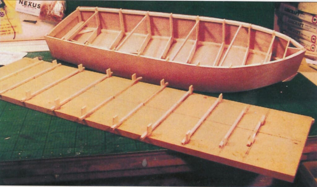
The size of Margoletta will allow the use of a 1/8 in (3mm) birch ply keel, built up frames and 1/64 in (0.5mm) ply for the side and bottom skins. I prefer to work on a base board with the frames extended to a common datum level, as it would be on the workshop floor in full size practice, and cut the extensions off once the hull is clad and is structurally complete, adding the cabin sides and decks later on up the right way.
Construction
I generally have some spare copies of the drawing run off at the local graphics shop so I can cut out the frames over the plan without worrying about damaging the original drawing. Cover the frame part of the drawing with tracing paper and construct the frames as shown, cut some strip 3/32 in (2.3mm) balsa 1/2 in (12.5mm) and 3/4 in (18mm) wide and away you go. I used 1/64 in (0.5mm) ply for the corner doublers and glued it together with balsa cement. If you prefer to cut each frame from lite or birch ply rather than building them up it is a simple process to transfer the shape onto tracing paper. Still extending to the datum of the building board you may cut as much out of the centre of the bulkheads as necessary to provide access to the radio and batteries etc., but remember the back cabin bulkhead and cockpit bulkheads are solid so perhaps it is easier to form small holes for wiring etc. at an early stage.
Trace the keel shape onto 1/8 in (3mm) birch ply and mark on the positions of all the bulkheads and the cut out for the stern tube. I used an 8 in brass tube of 5/16 in diameter but any similar commercial unit will do. Cut some 1/4 in (6mm) doublers to fit both sides of the keel and recess them to suit; lay the assembly on some spacers off the bench to glue it all together as the keel must be straight.
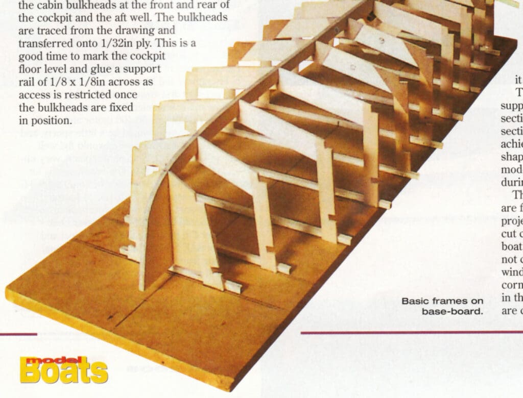
MDF board is good and cheap to use as a baseboard to erect the frames on. Draw a centre line on the board and transfer the bulkhead positions from the plan and draw with a square for accuracy. Each frame has a 3/16 x 3/16 in (4.5mm x 4.5mm) balsa rail glued across to allow the assembly to be glued to the baseboard which includes the transom. It’s important to use the centre line on the rail and baseboard to build a boat which is going in one direction and not round the corner!
When all the frames are set, offer the keel assembly into position and check all the slots in the frames are an easy fit. When they are all true use cyano glue to tack them in position, fillet the joints with balsa cement which is strong and waterproof. The chine rails and deck inwhales are next, fitted from 1/8 x 1/8 in (3mm x 3mm) square balsa laminated together as they bend easily. Chamfer all the seatings on the frames to the angles to allow the balsa to be glued and pinned until set. When the four pieces of balsa are fitted they make a good strong framework to attach the side and bottom skins.
The inwales are two strips of 1/8 x 1/8 in (3mm x 3mm) at the junction between the topsides and the deck; some 1/8 x 1/8 in (3mm x 3mm) strips are required each side of the keel between the frames to support the bottom skins. When dry chamfer all the rails to receive the side skins and bottom panels.
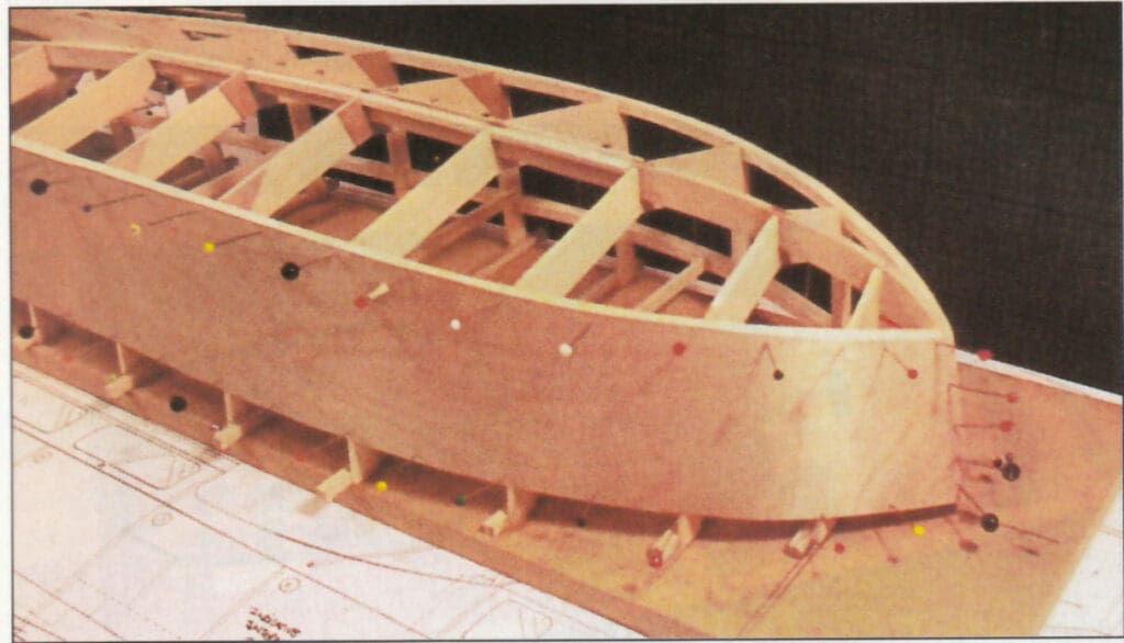
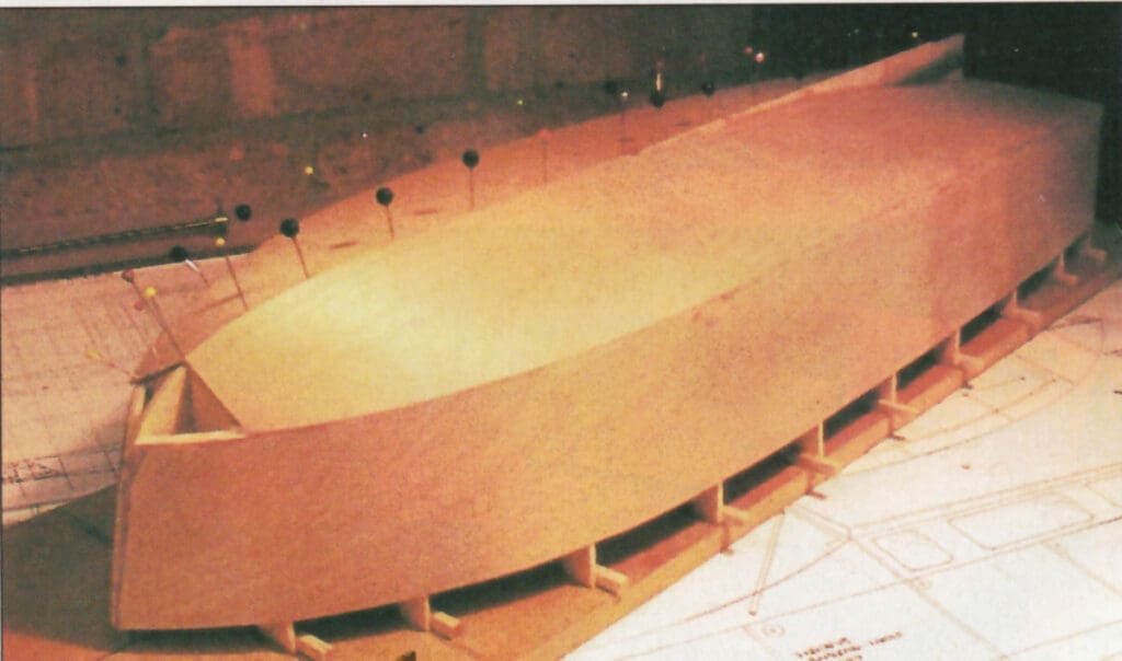
To cut 1/64 in (0.5mm) ply panels the right shape I use tracing paper laid over the framework, transfer the shape onto the paper allowing a little extra, turn the paper over and Hey Presto, you are in business. Glue the sides on and trim them flush when dry, followed by the bottom skins.
The small triangular section at the bow is infilled with soft block balsa and carved and sanded to shape.
We now have a complete hull and it’s probably a good time to drill for the rudder tube and assemble the skeg which is a brass strip to protect the rudder which can be supported by a pin soldered on, or use a commercial rudder trimmed to size. Prior to cutting from the building board fill any pin holes and rub over with fine wet and dry paper.
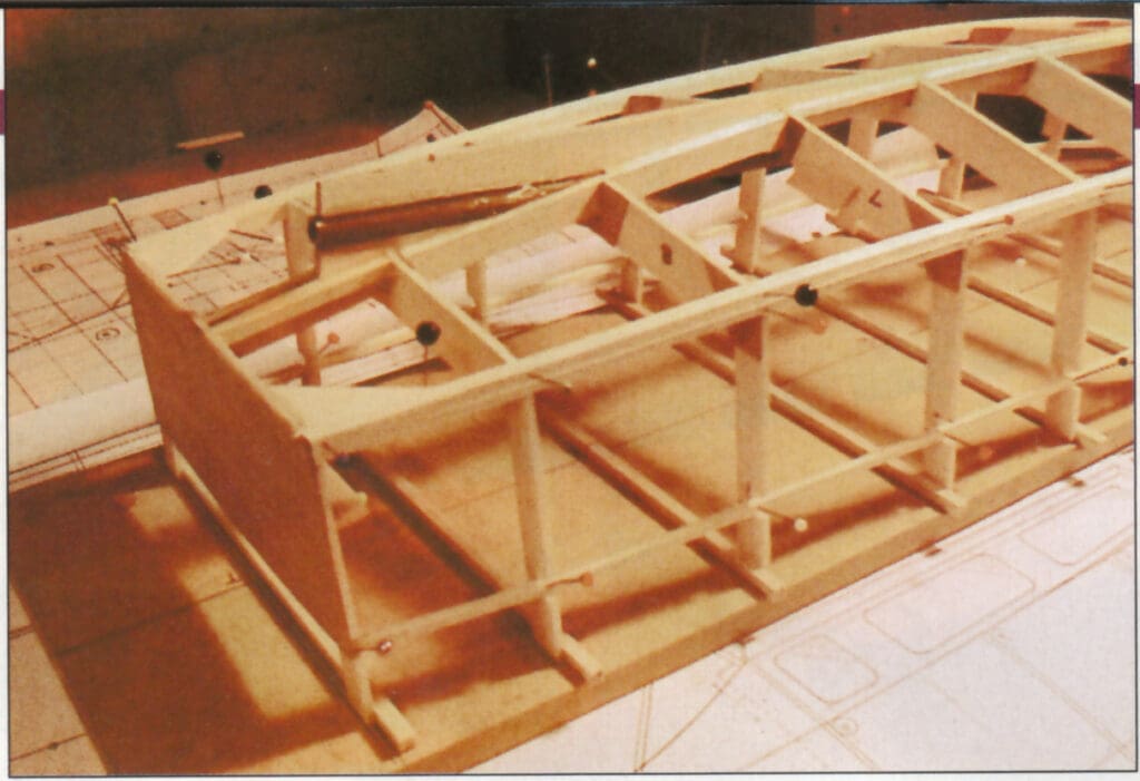
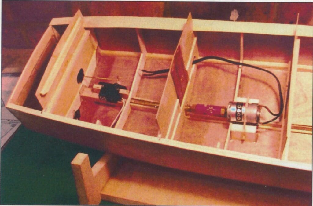
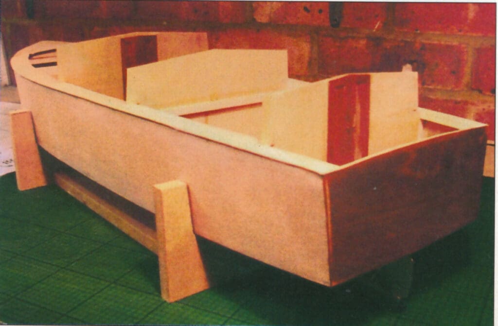
Once cut free from its building board glue some cross beams of 1/8 x 1/4 in (3mm x6mm) to support the cabin bulkheads at the front and rear of the cockpit and the aft well. The bulkheads are traced from the drawing and transferred onto 1/32 in (1mm) ply. This is a good time to mark the cockpit floor level and glue a support rail of 1/8 x 1/8 in (3mm x 3mm) across as access is restricted once the bulkheads are fixed in position
The 400 size motor and coupling should lie in the bottom of the hull with some 3/8 in (9mm) soft balsa as a cradle. I used servo tape to bed the motor with two dowels and a rubber band to retain it in position.
The fore and side decks are 1/32 in (1mm) ply supported by a curved beam across at section 2, the side decks gradually run flat by section 4; again I use a card template to achieve a good fit prior to cutting the final shape. I would not trace the plan direct as models, as with the full size, move around during construction!
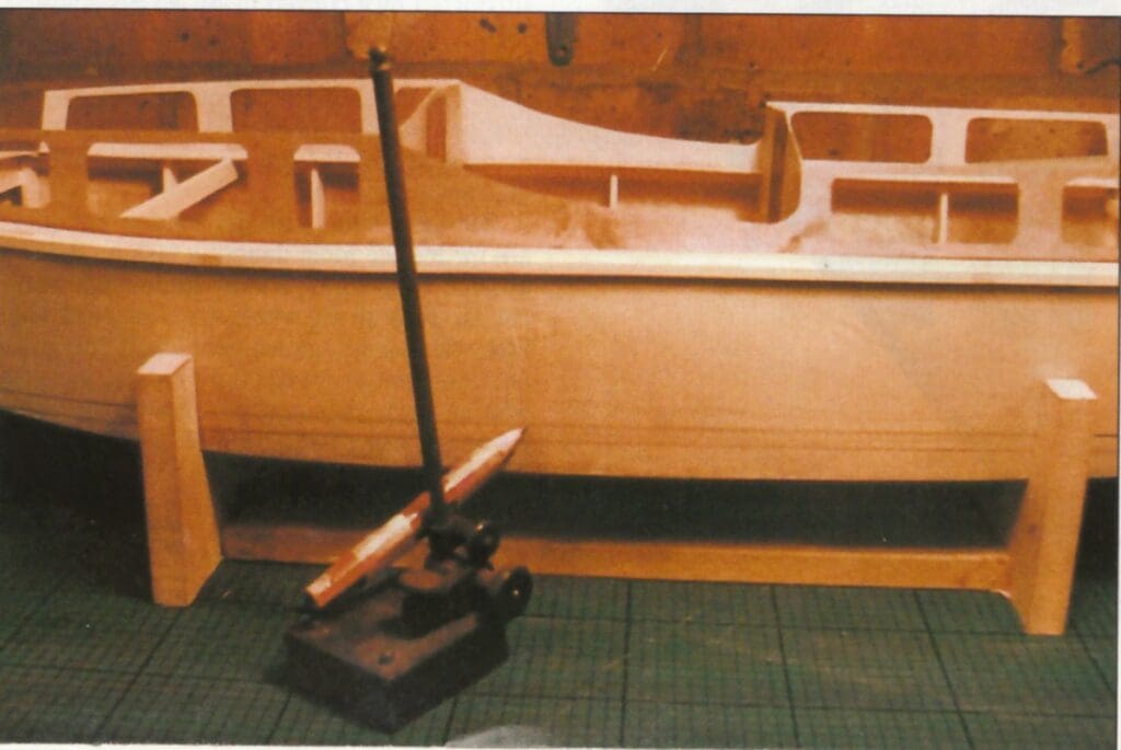
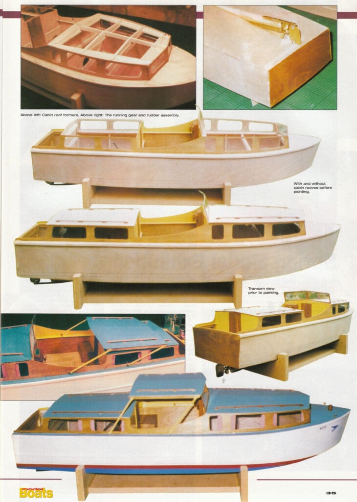
The cabin sides with the window cut outs are for me the most daunting task on the project. Take a new Stanley knife blade and cut carefully as the whole appearance of the boat will depend upon a neat job, if you are not confident to cut the tight radii in the window corners stop short and file the corners; your patience should be rewarded in the end. The cockpit floor and inner sides are cut to fit the gap between the bulkheads.
I have shown a small engine access cover for the crew to trip over when drunk which is cosmetic as the floor can be removed for motor and coupling maintenance purposes.
The cabin roofs are built in situ with a balsa framework with a central support spine to take the 1/64 in (0.5mm) ply panels. Again paper templates are worthwhile to achieve a neat margin to the cabin edge. The roof grab rails are mahogany strips with short sections glued on and rounded to create a usable section. The cabin windows are acetate or celluloid sheet glued in with epoxy. If you use standard cyano glue they will go misty and be spoiled. The windscreen is formed with clear plastic from a CD case with framing epoxied on for the framework. The cockpit roof is movable on its four supporting tubes which allow the roof to be laid down upon the aft cabin for going under low bridges. I used 1/8 in (3mm) brass tube flattened and drilled 1/16 in (1.5mm) for pins or 10 BA bolts and nuts. The actual dimensions should be taken from the job when the roof is packed level to the waterline. Spacers may be required where the tubes are attached to the cabin sides to allow full movement.
Finishing
The really good part of using 1/64 in (0.5mm) and 1/32 in (1mm) ply is that a couple of coats of dope or sanding sealer is all you will need to prepare the hull for painting and decorating. Many Broads Cruisers are varnished hardwood. This can be achieved easily with wood stain; I used Burmese Teak on the prototype sealed with matt varnish. Anything too glossy I feel looks wrong on a small model of this size. Visit your local dolls house shop and buy some material with a fine print pattern and hang/glue some curtains at the windows – it will look much more ‘lived in’.
Deck fittings
These are sparse which is good from a modelling angle; two T shaped cleats fore and aft without fairleads seem to be standard for the period. I thought a substantial king post on the foredeck would be useful if she needs to be towed at any time. Navigation lights are not fitted to the hire fleets as they are not allowed to run after dark on the Broads. Cockpit details are a personal choice of where to draw the line on detailing.
Radio
Radio installation and batteries I will leave to your own good judgment! Just keep it out of the bilges! When all the electrical equipment is aboard test in the time honoured way in
the bath and ballast her down to her waterline; the prototype required 1.5 lbs (0.7 Kg) in the forward cabin with an 8-cell AA pack of batteries in the rear cabin. I will be changing over to some brand new lead acid accumulators I’ve had in store for 25 years in the near future and remove the ballast.
Sea trials
I am very fortunate to five close to the River Medway in Kent. I am indebted to Mr. Peter Larkin, owner of Allington Marina, for the use of his slipway and basin which was ideal for Margoletta’s first voyage amid her big sisters.
Now many seasoned boaters may have noticed that the speed 400 motor and 8 cells providing 9.6 volts would be a little sporty, and indeed if she had wings she would fly! Well she will certainly get up on the plane, very unscale like but good fun. The conclusion is for running at a scale 5 mph we will only need 3-6 volts. She responds well to the rudder and looks the part on the water; perhaps my next effort should be an off-shore power boat; however I’m planning the next project and that’s a BAE Hawk! But I really enjoy boat building from scratch.
P.S. If any readers know the whereabouts of the drawings for any of the full size Porter & Haylett Broads cruisers built at Wroxham, I would be very interested in details.
This article originally appeared in the June 2005 issue of Model Boats. Plans for Margoletta are available from Sarik Hobbies Ref: MAGM2024.