John Mileson presents a very versatile pre-moulded hull based project.
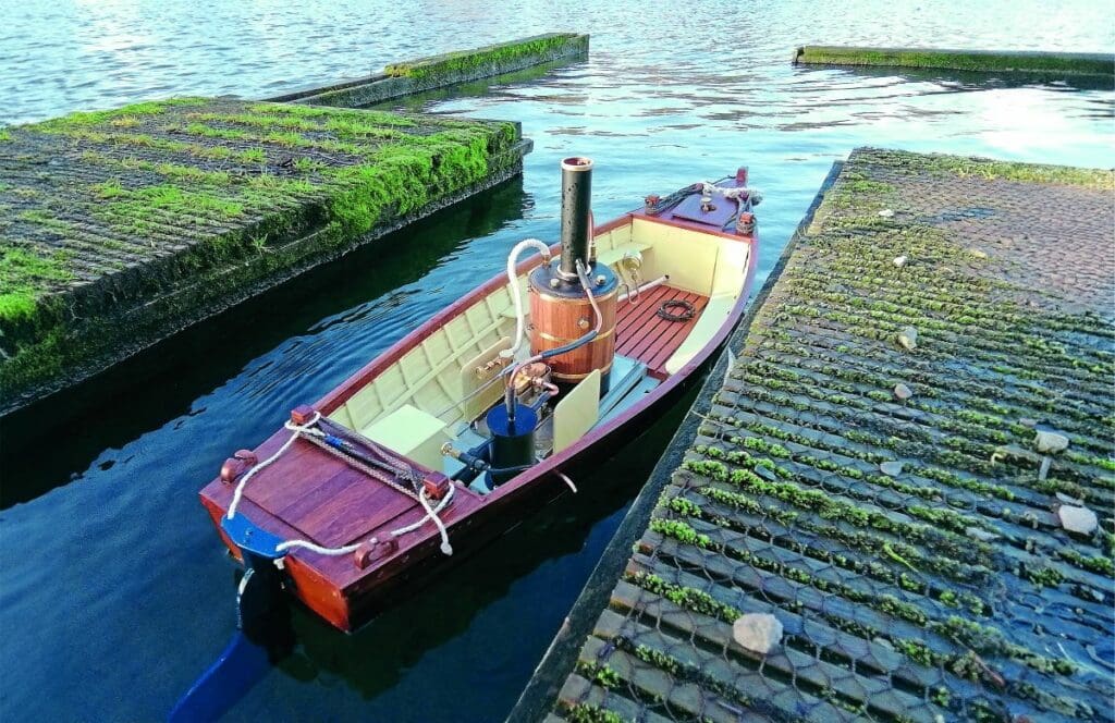
If, like me, you’re a Daphne du Maurier fan and familiar with her novel Frenchman’s Creek, you may, considering the title of this article, be expecting a pirate ship build. If so, sorry to disappoint. Despite having no actual association with the book, I just couldn’t resist adopting La Mouette (the Seagull) as the name for this particular build, based on Orion Mouldings’ superb fibreglass ‘wood effect’ river launch hull (see Photo 1).
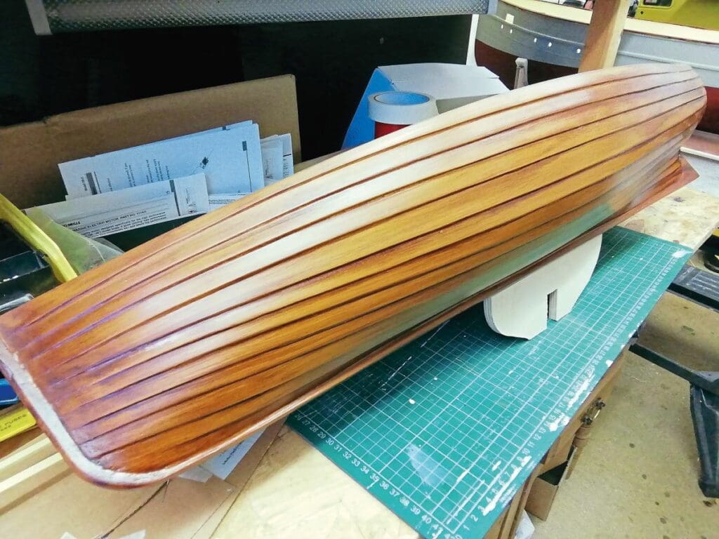
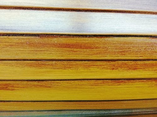
I was immediately excited about putting Orion’s hull to good use, because, as can be evidenced in my close-up (see Photo 2) the wood effect really is most convincing.
Enjoy more Model Boats Magazine reading in the monthly magazine.
Click here to subscribe & save.
Measuring 35 inches long, with a beam of 10 inches, I found this hull to be ideally suited to steam propulsion, but it could just as easily employ an electric motor as its source of power. In either case, much of the construction would follow the same build pattern.
As I’d elected for steam power, I decided to use one of the Clevedon Steam vertical steam plants; the beauty of these is that they can be swapped over between models in a matter of minutes – although personally I like to put a new plant in each model. Anyway, if, like me, you do decide to purchase a new steam plant from Clevedon Steam for the purpose of this build, the one to go for is the Virgo vertical steam plant, which includes the engine.
Fitting out the hull
I should point out that the Orion hull does not come with any instructions or plans. Looking at this from a glass half full perspective, though, what this means is that the simplicity or complexity of your build will be entirely up to you.
Before getting started on the build itself, I first constructed a cradle to support the hull while working on it. This was made up from 9mm birch faced plywood.
I then thoroughly washed, dried and then wiped over the hull over with a meths soaked cloth. This may not actually have been necessary, but the idea was that, hopefully, all releasing agent would be removed (I steered clear using bathroom cleaner for fear of scratching the wonderful wood effect finish).
The inside of this hull is finished in black, which, of course, if wishing to simplify the build could be left as is, or, if you’re prepared to go the extra mile, painted in an appropriate colour. However, to make things more difficult for myself, I decided to mimic the external planking with wooden strips inside of the hull.
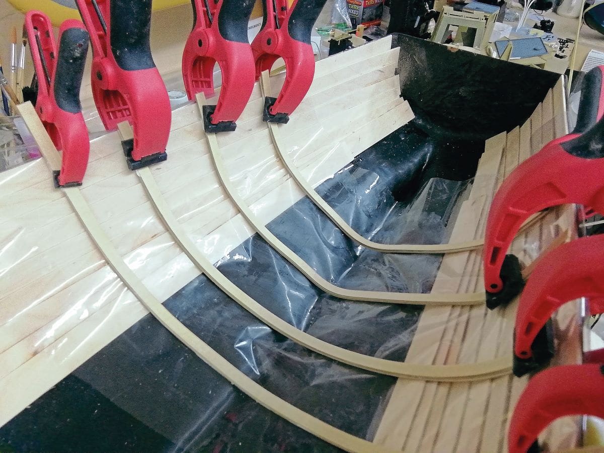
For this inner planking I used 1.6 mm birch faced plywood, cut into 20 mm strips, with the edges carefully sanded down to remove any possible splinters. I wasn’t quite sure which adhesive to use to secure these planks to the hull, but in the end opted to use epoxy resin (5-minute). I fully expected I’d need a couple tubes of this, but the reality was the job took four!
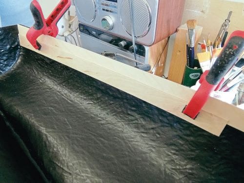
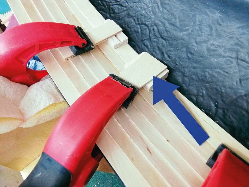
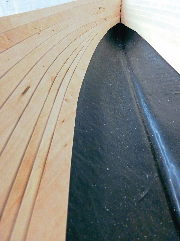
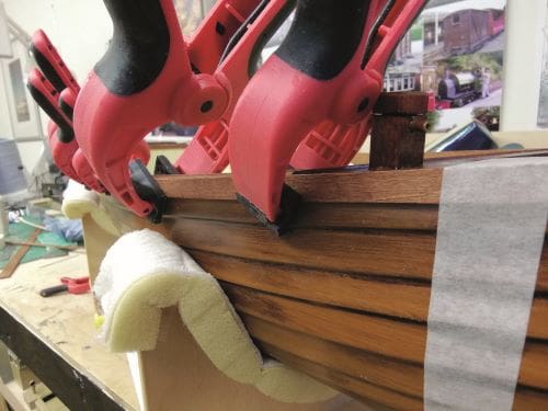
Fitting the first few planks proved easy, the plywood easily bending to the inner curves of the hull (see Photo 3). It did however, become increasingly difficult to form the planks the deeper they went into the launch. Indeed, because the clamps wouldn’t reach into the full depth of the hull, wooden extensions had to be made to hold strips in place (Photo 4). But, while not perfect, I was pleased with the end result (see Photo 5).
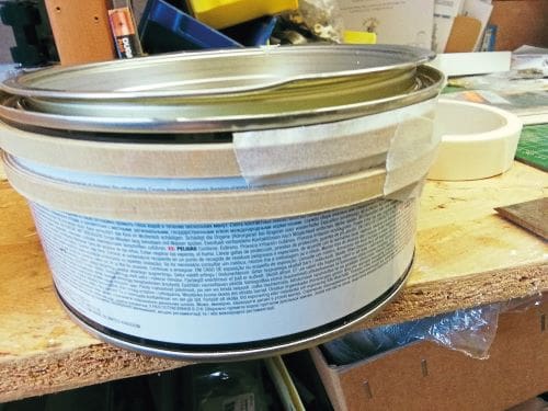
I knew making the ribs would prove tricky, as these had to follow the contour of the inner wood-clad hull. I experimented using strips of .8 mm plywood cut across the grain. Each strip was 6mm wide, and three strips made up the full thickness of the rib. To see how effective this would be, the strips were glued together with aliphatic resin and taped around a tin of a similar diameter to that required (see Photo 6).
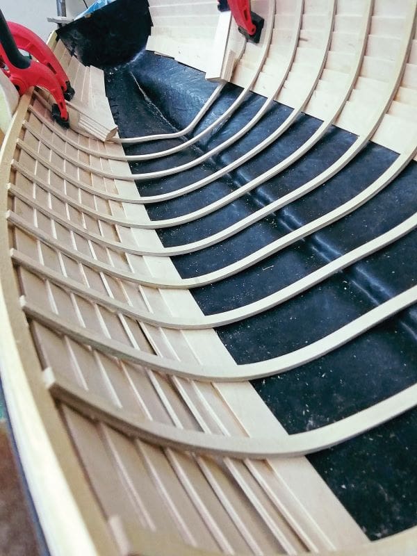
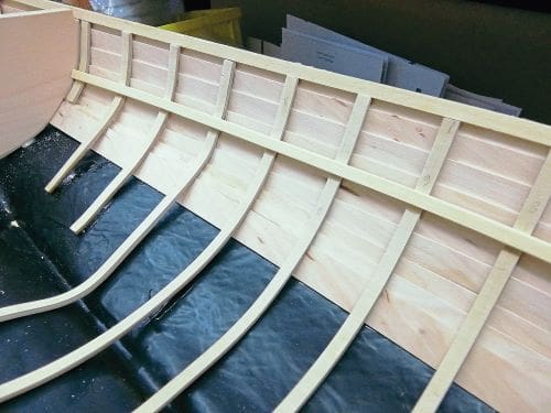
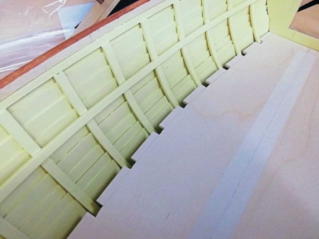
The finished ribs were amazingly strong, but were, of course, the wrong contour. The method I had to employ therefore was to bond the strips together and, before they set, clamp them around the inside of the hull until the glue went off (see Photo 7). Cellophane was used to stop the ribs sticking to the planking. By doing this I was able to bend them slightly to shape while gluing them into the hull (see Photo 8). Fortunately, the overall effect proved satisfactory (see Photo 9).
The prospect of drilling through for the propellor shaft was a cause for concern. The proposed shaft was 6mm diameter and the moulded keel about 8mm across. I don’t mind admitting it was with some trepidation that I drilled through into the hull. As it happened, the drill broke through along the centre line of the hull but at a steeper angle than was expected. Filing out the resulting hole eventually remedied this, although the hole was decidedly egg shaped!
I was loath at this stage to progress the hull any further, since the steam plant had not been delivered. In the meantime, therefore, progress was made on the rudder assembly.
The rudder assembly
Before making the rudder, the servo unit was fitted in the stern beneath the small deck. I used 9mm plywood for the support bracket for this servo, as I need something thick and solid to for screw it onto; I am always aware of the tremendous force that servos can exert.
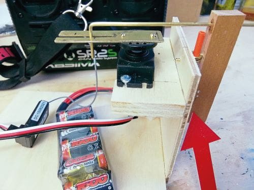
The proposed rear deck was to be fairly small, so a means of activating the rudder was devised, using a slotted arm attached to the servo. Being unsure of how efficiently this would work, a mock-up was first made and tested (see Photo 10). It worked well, so provided this could be replicated on the transom of the boat, all should be OK. The original slotted arm test piece was replaced by an aluminium version.
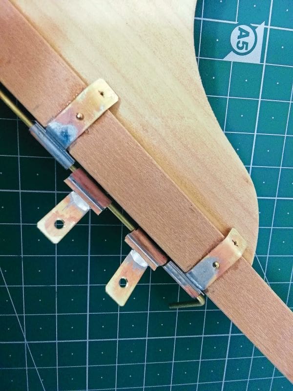
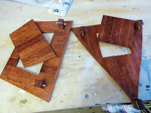
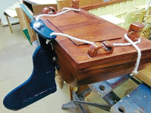
The rudder itself was made from scrap pieces of Parana pine and teak. This was simple enough, but the ‘pintle and gudgeon’ hinge was going to be the difficult part. In the end, I made up a long hinge plate, consisting of a length of brass tube soldered to a strip of brass. Across the strip of brass, and at right angles to it, strips were soldered on at the same time. The ‘hinge’ was then cut into 12mm lengths. Two would be screwed to the transom, and two attached to the shaft of the rudder. The latter two would be glued and pinned. The pintle and gudgeon are illustrated in Photo 11. The finished rudder blade, and stock, plus the ‘hinge’ are shown in Photo 12. My rudder assembly was then temporarily fitted to the transom and tested. All worked just as I’d hoped.
The fore and aft decks were made from 3mm plywood. Pre-stained (teak dye) 1.6 mm plywood planks were then glued onto the plywood bases (see Photo 13).
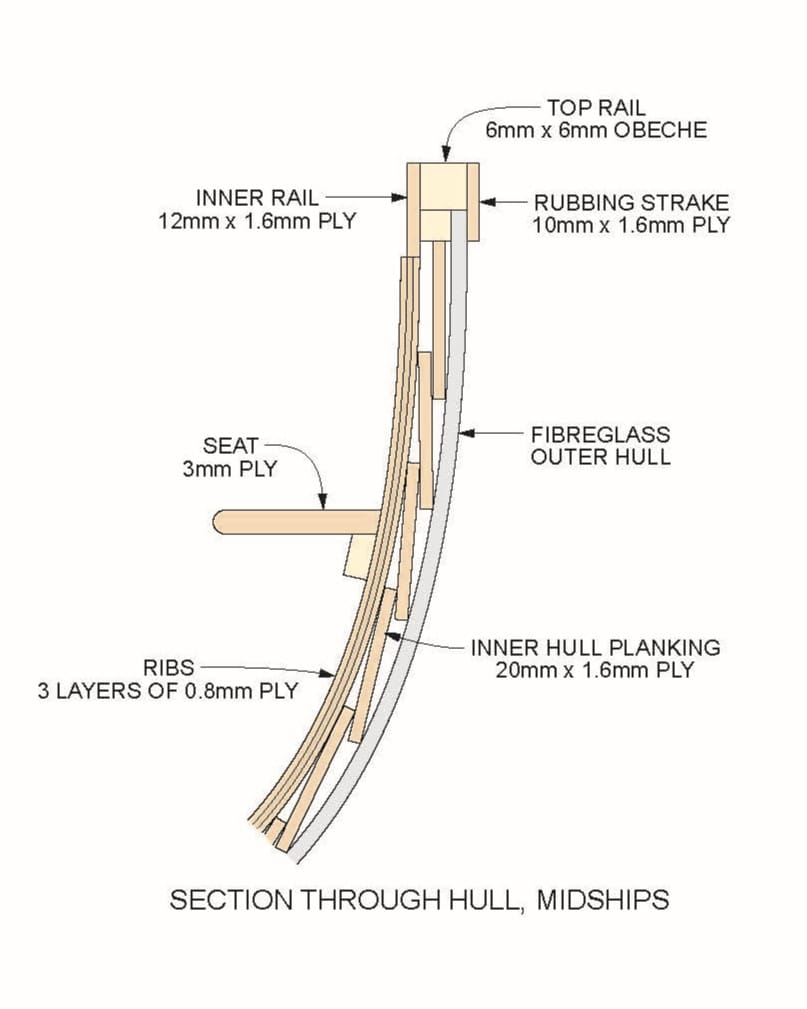
The inside of the hull was given a coat of sanding sealer, followed by two coats of gloss enamel. It was, as can be imagined, a tedious job ensuring all facets of the planks and ribs were well coated and without runs. Once dry, the fore and aft decks were glued on. Work to complete the gunwales, particularly the top ‘handrail’ followed. As can be seen from my sketch (see Photo 14), the gunwale was made from a series of strips of obechi and plywood. The assembly and fitting of these strips turned out to be an easier job than anticipated. Finally, once set, the rails were sanded down, stained with teak stain, and satin varnished (see Photo 15).
The inner hull was now complete, save for the fitting of a ‘floor’, the steam plant and accessories.
The ‘floor’ was made from 3mm plywood (see Photo 16), which although would be hardly seen was painted with grey primer and gloss varnish.
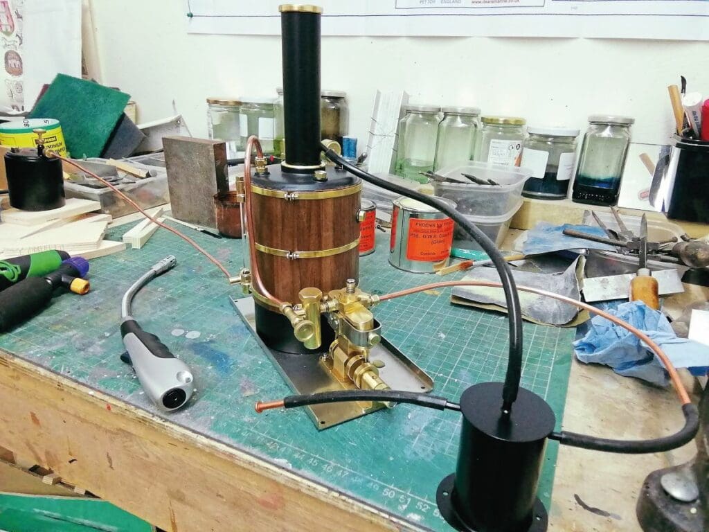
Next came the assembly of the Clevedon Steam boiler and engine. This proved fairly easy, the most time-consuming part being fitting the wooden insulation to the boiler. It was then steam tested on the bench (see Photo 17). This is always an exciting time for me – clearly, I need to get out more!
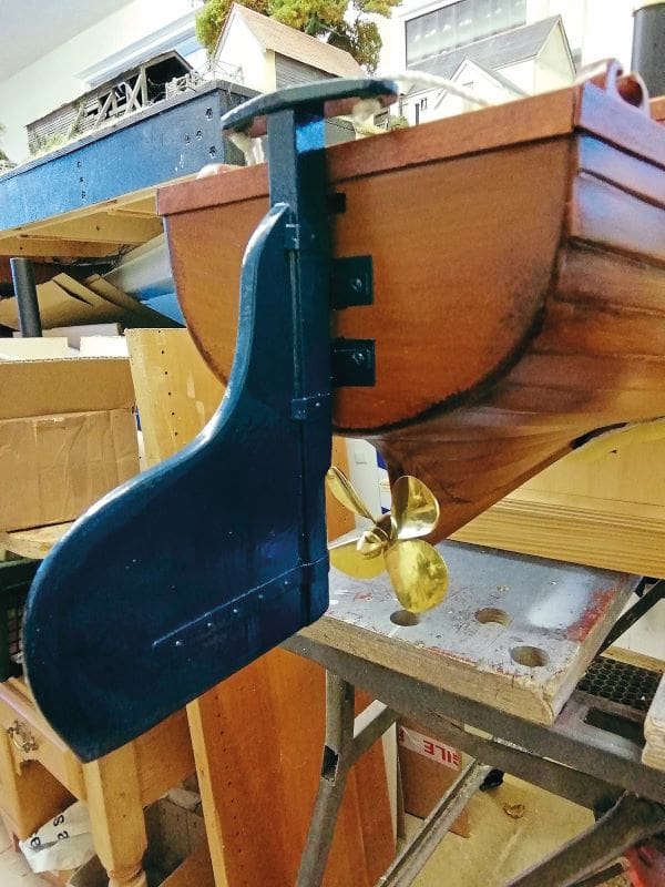
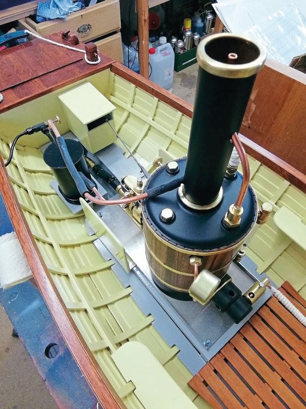
The pre-made rudder assembly could now be fitted (see Photo 18) and the electronics tested to ensure everything was working. The drive train, propellor shaft, propellor and universal joint were also fitted, and the engine and boiler were bolted down to the previously fitted 9mm plywood pad (see Photo 19).
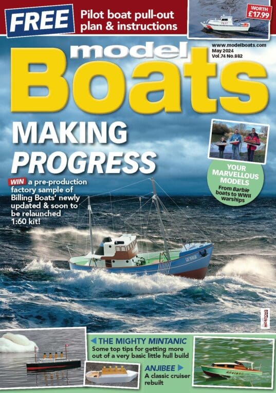
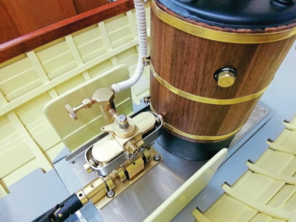
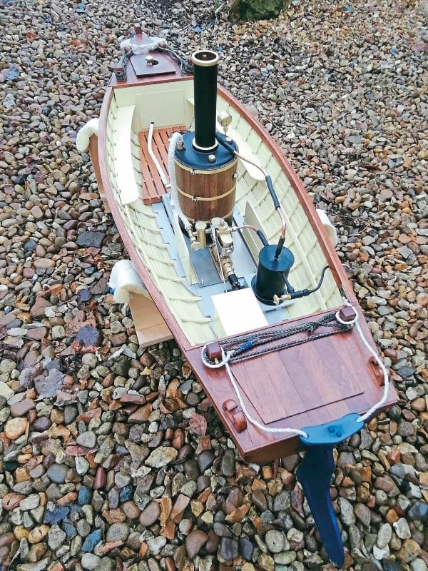
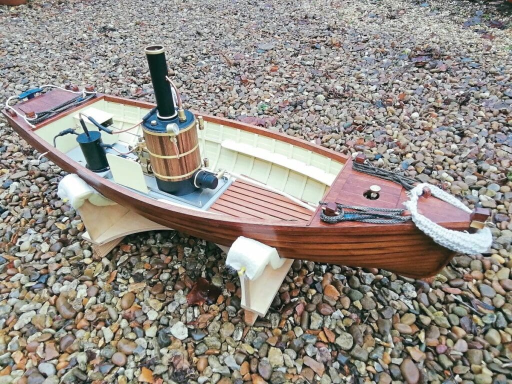
All that remained to be done was the installation of the servo for the regulator on the engine and the condenser (see Photo 20), and some minor detailing. My launch was complete (see Photos 21 and 22).
Over to you…
This is a fairly simple build, based on two tried and tested components: the Orion hull and the Clevedon Steam engine plant. As previously mentioned, there are no plans to work from, but that’s no bad thing. Why? Well, once the position of the engine plant in the hull has been determined (by testing in a bath of water), you can pretty much do as you please. There’s no need to fit planking to the inside of the hull, and indeed there’s no need to fit a fore and aft deck. You really can either keep things very simple or totally go to town on the detailing – the choice is yours. In either case, I’m confident you’ll find this a most rewarding project. Go on, give it a go!