With only one previous scratch build under his belt, Chris Wood fearlessly takes on another massive project….

“I think my next model will be a 1:8 scale lifeboat”, I said to my wife, Emma. “Hmm, OK…” She didn’t sound overly convinced. In fairness though, I’d only begun scratch building 18 months prior to this while furloughed from work during the pandemic. In my teens I’d been into R/C cars and aircraft, and I’d built the odd Airfix kit, but this was an altogether different and more complex modelling discipline. My first ever scratch built project, prompted by time on my hands during the 2020 lockdown, had been the Svitzer Milford Haven. I used plywood for most of this boat, due to the fact it’s easy to cut and shape using basic tools, and, as I was working from pictures found on the internet, I made a cardboard man to aid with scaling. I bought components like lights and thruster units but made many of the other parts simply from what I could scavenge from the garage and garden shed.
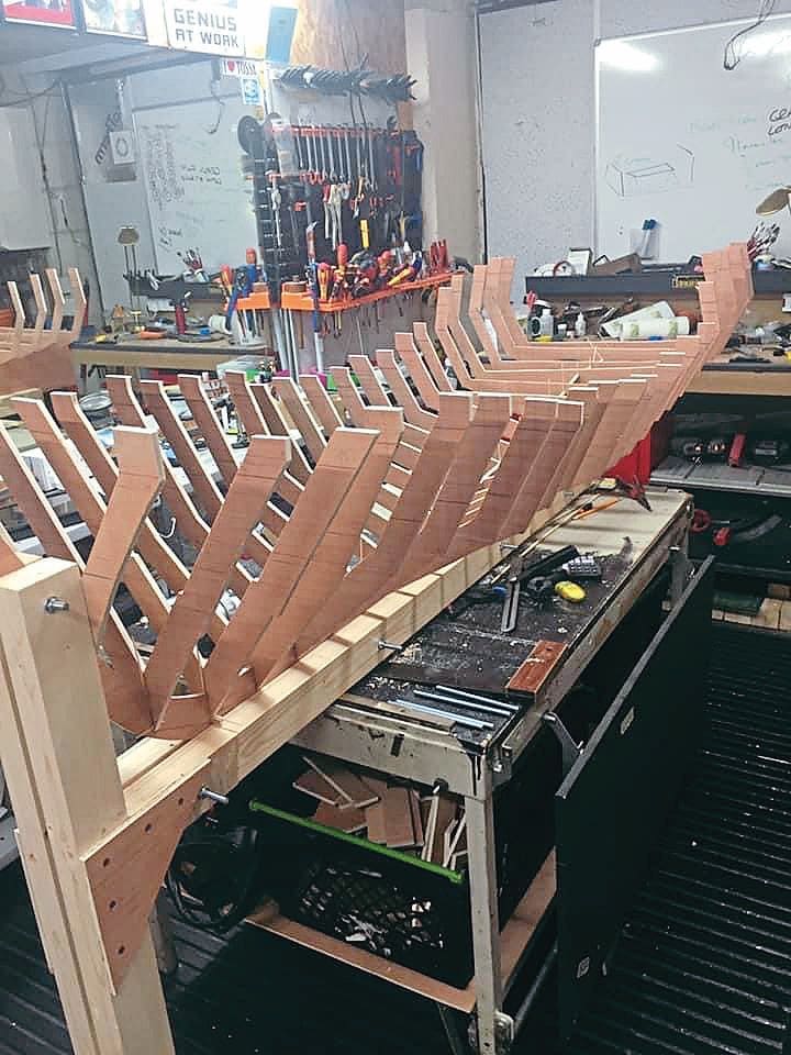
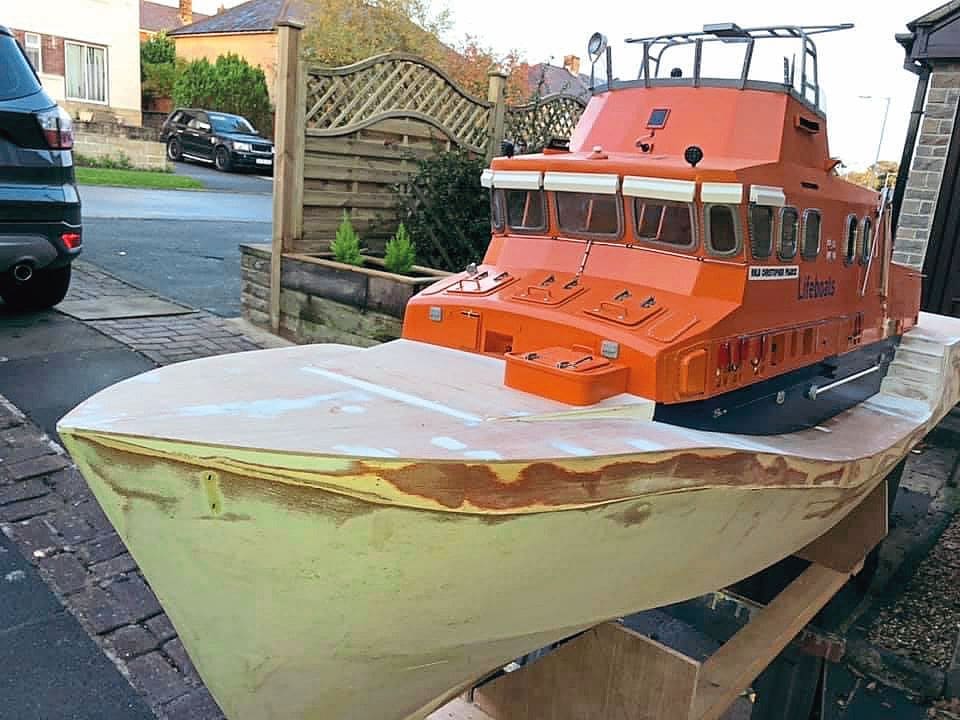
Having pushed myself beyond my comfort zone and achieved both my end goal and a real sense of satisfaction, it wasn’t long before I began considering what to build next. As mentioned at the beginning of this article, I decided on a lifeboat, a Severn class lifeboat to be precise. Although admittedly ambitious, I liked the idea of making everything from scratch, including the Rib launch and crane. I did, however, buy an Airfix 1:72 scale RNLI Severn class lifeboat kit as a reference point from which I could figure out the hull shape. After doing the maths. I scaled up and drew my own much, much larger hull sections and keel onto plywood sheets before cutting them out.
Enjoy more Model Boats Magazine reading in the monthly magazine.
Click here to subscribe & save.
An epic build begins
As I began dry fitting the frames to the keel it started to dawn on me what a monster of a build this was going to be. At this point, even family and friends raised their eyebrows and asked “Why?”. Well, why not!
Once happy with the frame positions on the keel, I cut the deck supports and glued them to the frame sections. I then made a second jig so I could invert the hull frames, thereby allowing me to attach the keel; this ensured nothing would move out of alignment while I was attaching the plywood sheeting to the ribs. Plenty of glue was used, and I invested in a compressor, a staple gun and lots of clamps. Where the timber curved to the bow, I temporarily screwed on the sheeting. The curved section where the propellers sit was fashioned from thin strips of ply, glued on and later filled, along with the low spots and imperfections, followed by plenty of sanding.
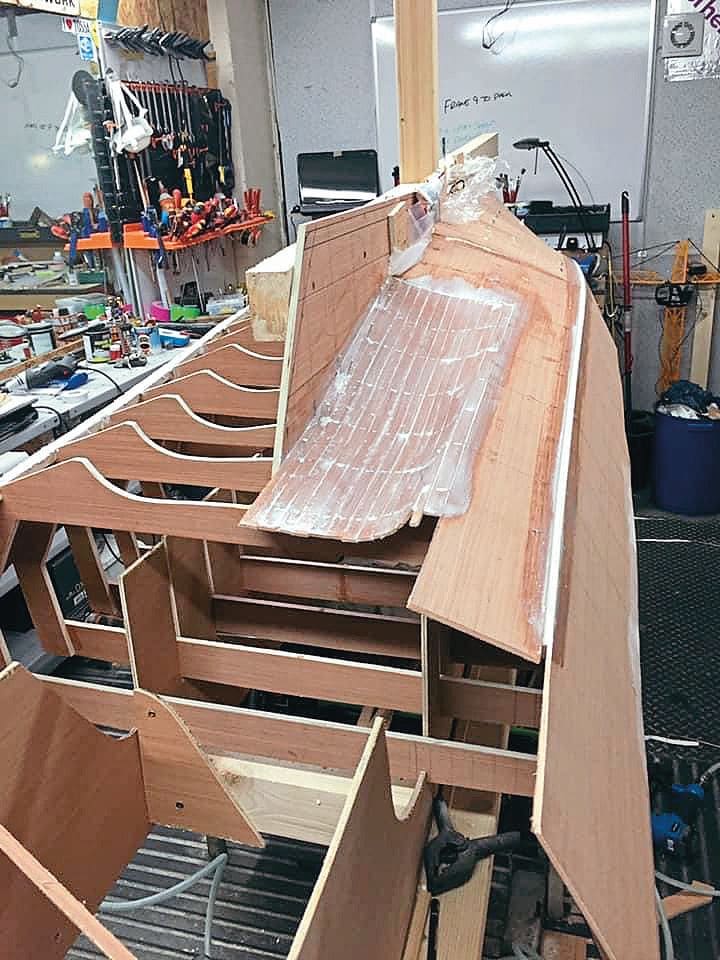
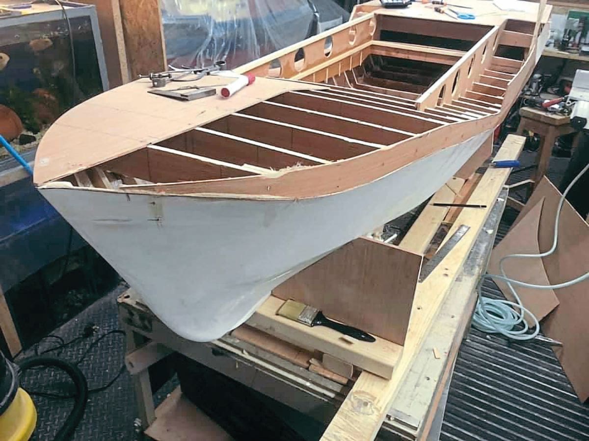
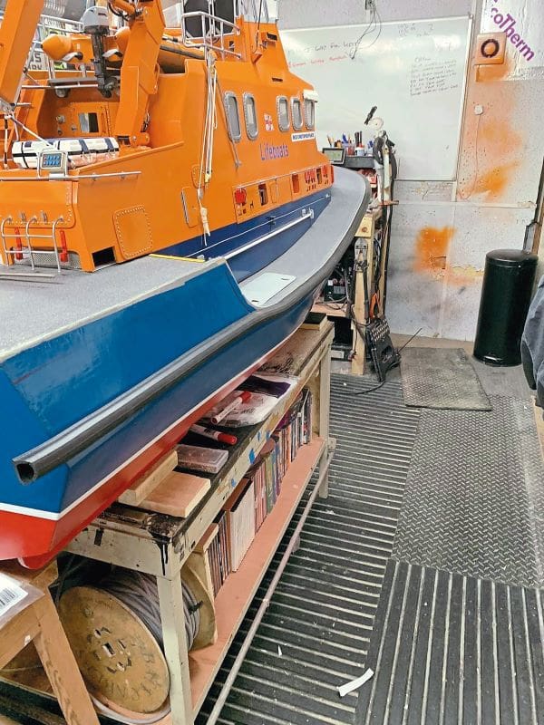
After removing the hull from the jig and turning it the right way up again, work commenced on fitting the decking using the same method, along with making the steps in the hull at the stern and the centre section which the cabin would sit over. I also added fibreglass sheeting to reinforce the hull where the motors would sit. After many hours of sanding and filling the hull, I was happy and ready to proceed with the construction of the cabin.
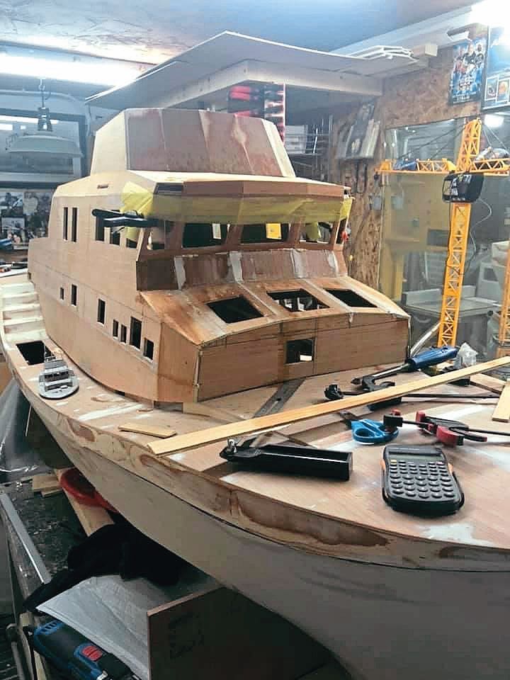
Creating the cabin and flying bridge
I started off with the two side pieces, carefully cutting and shaping them to sit on the deck. I then marked out the openings and outlined the shape of the cabin. Next, I glued cross supports in place and started building the rear section of the cabin. Once the rear section was glued, I was the able to add the roof section and the flying bridge. A lot of work was involved in getting the angles correct and keeping everything level and plumb. At times it was slow going, as I had to wait for the glue to dry before proceeding further.
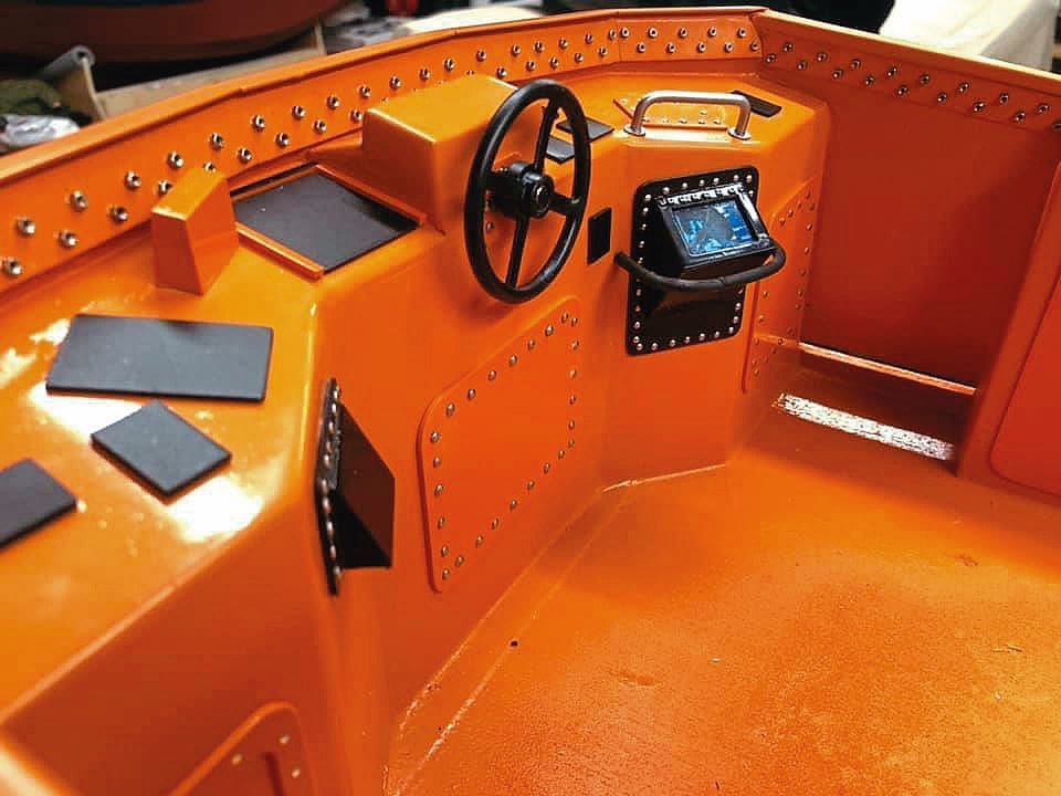
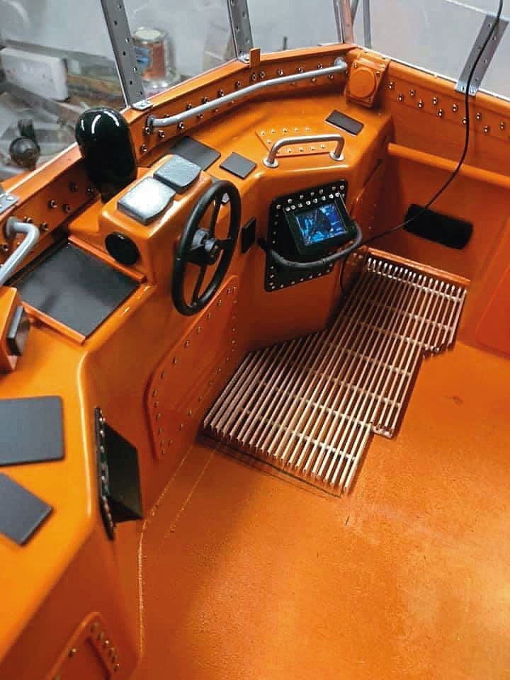
A few weeks later, most of the plywood work had been done, and I was able to create the flying bridge console area from Plasticard and use some plastic tubing for the gantry over it.
I fitted some brass strips around the flying bridge and used a punch to create the effect of bolts around the windows. I used Plasticard, again, to make the front hatch, the hatch surrounds, hatches and pates. The front hatch hinges were made from scrap metal and here I had to learn how to silver solder, so a few failed to make the grade and had to be scrapped, but I was learning.
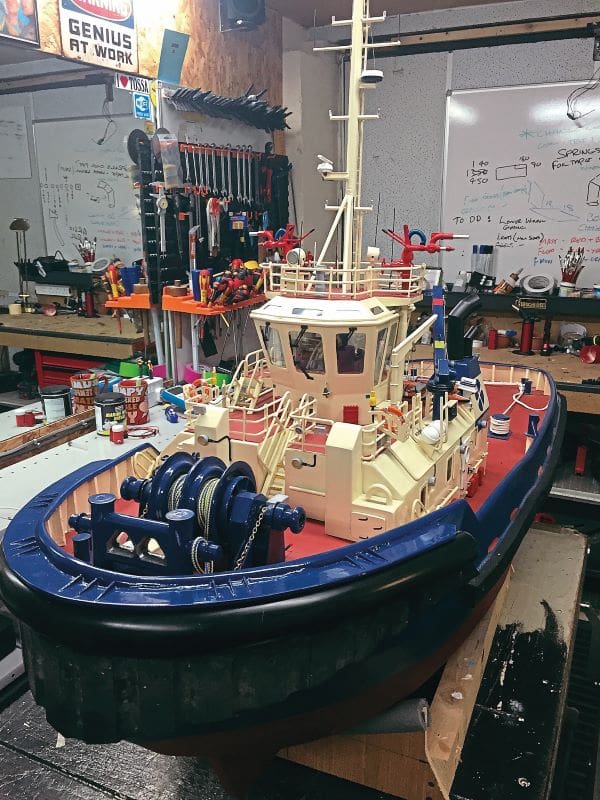
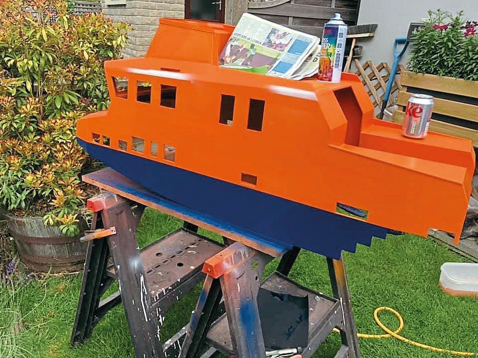
With the front hatch complete I was ready to start painting. As a practice run, I trialled the orange I had selected on some of the smaller items first. Then, as it was February and still very cold outside, I left the cabin and hull for the time being and turned my attention to the crane. As I have a small metal lathe, I decided to make this and the hydraulic cylinders from metal. My initial attempt at a crane turned out to be very heavy, though, so I scrapped it off and made began again, using aluminium to keep the weight down. I was still learning how to silver solder, so in between working on the crane I was also making more hinges for the cabin hatches.
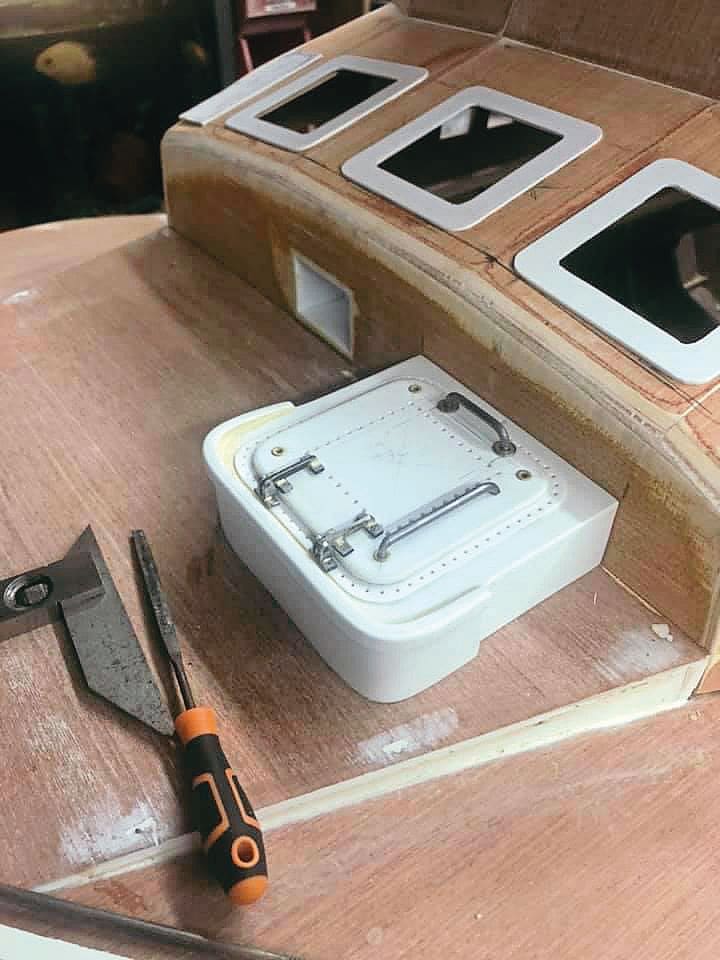
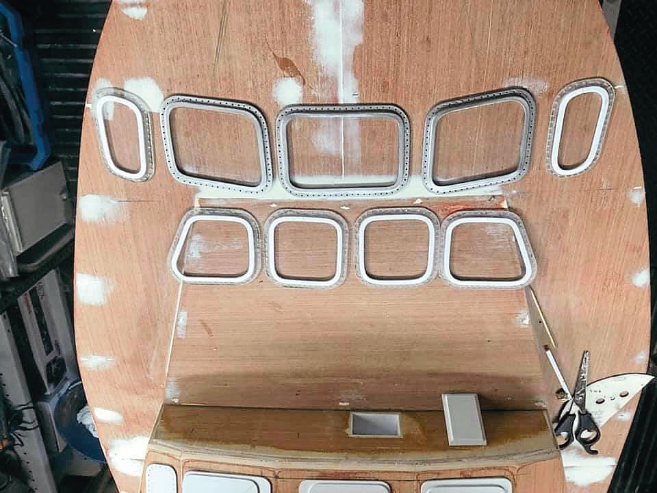
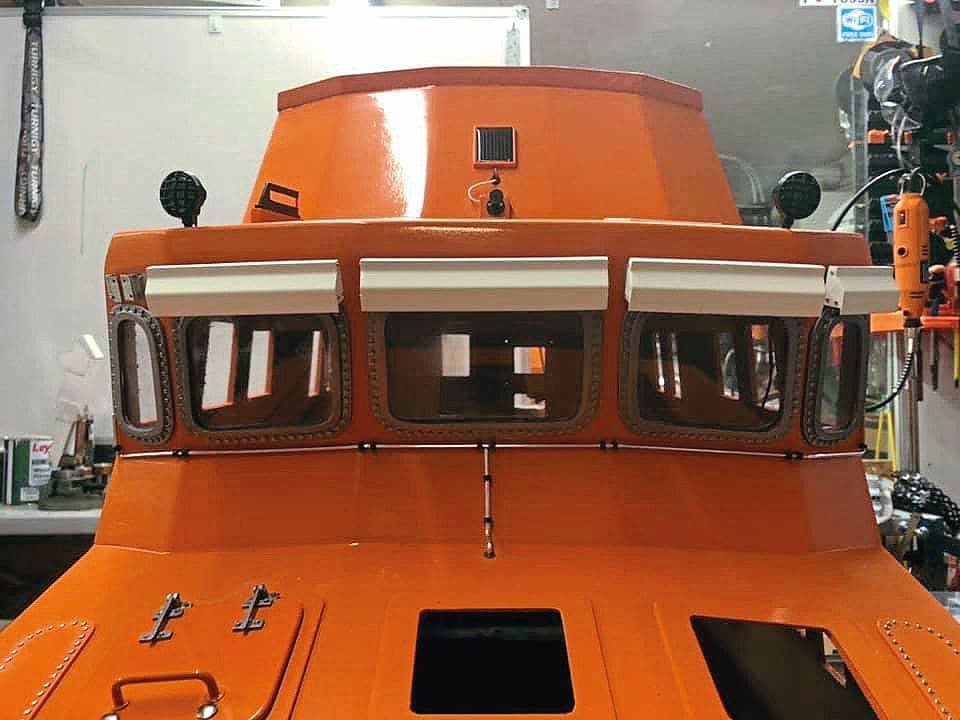
Probably the biggest challenge I encountered was getting the window frames right. On the real boat they are impressive and replicating them was a struggle. I was determined not to 3D-print or outsource, so I persevered and finally figured out a method that worked. Basically, this involved gluing the frame to the Perspex before shaping and drilling, masking the window and spraying the outer silver trim, drilling out the surround and screwing to the cabin with minute screws. I rejected more windows than I used and fitting them was an uphill battle too, but ultimately well worth the effort.
By April the weather had warmed up enough to start working outdoors so I began prepping the cabin for painting by sanding and filling. I also primed the hull, but to give myself sufficient room to work, I stored this away in the shed so I could first concentrate on the cabin.
Painting the cabin was a big job. I bought so many tins of Volkswagen Orange from Halfords that they kindly gave me a trade card! Once this orange had been applied and allowed to harden, the blue was applied. Finally, the whole lot was given a few coats of clear lacquer to seal. I was now ready to start assembling.
The hatches and front window frames were fitted first (the tiny screws making this a very time-consuming job) and I also started fabrication of the wiper boxes and began construction of the gantry. I also made a start on the flying bridge and crafted a steering wheel and other smaller items. Due to the cabin being so big I could have worked on different areas simultaneously and made a lot more progress, but at this stage I tried to focus on the front only so I wouldn’t become overwhelmed by how much work there was to be done.
I used brass strip soldered together to create the window frames for the flying bridge, and I drilled 1mm holes into these so I’d be able to fit tiny nuts and bolts that would secure the windows. I also made handrails from metal rod bent at either end, and glued tiny nuts to the inside of the flying bridge, plus I fitted some panels and drilled out and glued silver pins to represent bolts. I really went to town with the detail on the flying bridge and enjoyed getting creative. For example, I made the spotlight from an old electric motor casing and some scrap brass I had to hand, while the floor was created using coffee stirrers (regularly swiped from our local Costa by the dozen whenever my wife and I popped in for coffee and cake!).
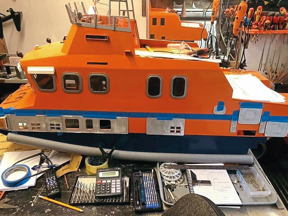
The side panels/plates were made from aluminium door push plates (the width being just about spot on), which I found could be cut using a sharp Stanley knife. The panels proved very time consuming to make and a few failed. I seemed to spend a lifetime drilling all the holes out for the stainless-steel pins, but they painted up beautifully.
Again, in between fitting panels I began fabricating other items, like the two frames for the sides of the cabin and some of the handrails. I then continued along the port side working towards the rear of the cabin. The steps to the flying bridge were made from scrap aluminium, along with some more panels too, so every few days I could batch spray. The light units were fabricated from bits of plastic and, likewise, pins and fittings from scrap brass. I even made padlock and locker handles (from filed down nails).
Once the decals I’d ordered arrived and I’d applied them to the port side, the cabin looked amazing. All the hard work and endless days spent drilling, screwing and gluing pins had paid off. This gave me the boost I needed to keep going. The orange and blue starboard side still nothing had fitted, so it was time to start the process all over again…
Constructing the crane
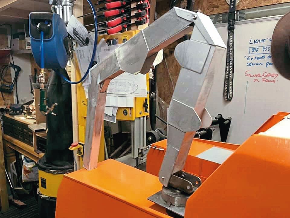
The starboard side features a crane, which, as previously mentioned, I’d already made a start on. I’d built the shoulder but still had the rest to tackle. So, I ordered some more aluminium push plates and plenty of Stanley blades and began construction. A fair bit of tweaking was required to get things square and ensure each hole was in the right place. I made my own hydraulic rams, too. In fact, I enjoyed working on the crane so much this actually became my sole focus for a good couple of weeks.
Getting back to the side panels, etc, I was able to paint these at the same time as the crane.
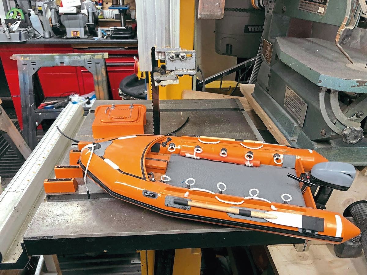
How and Y
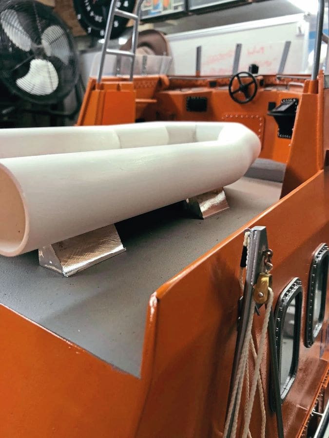
With the starboard side complete and the crane fitted, my attention turned to the Y boat at the rear of the flying bridge. Having first built a successful test trial prototype, a plastic waste pipe was cut at angles and superglued, while the floor came courtesy of some scrap plywood. The finished Y boat really looks the part, especially now painted. The stand it sits on was built from some scrap aluminium.
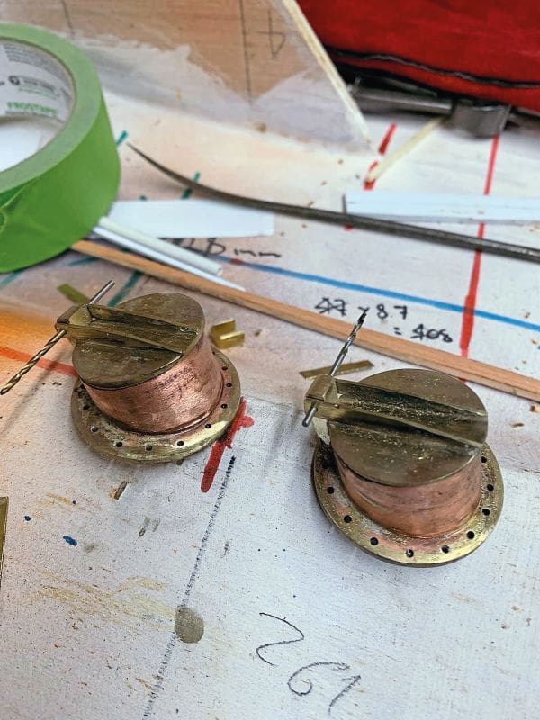
I also used some scrap metal and brass cylinder for the creation of the bow and stern bollards.
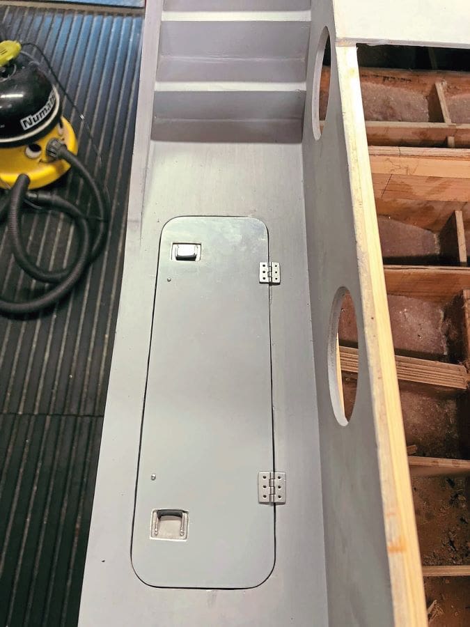
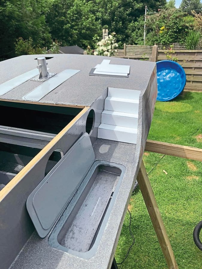
It was now time to bring the hull back into the garage and get the deck sanded and primed and the cabin back on so I could work on both. I cut out the port and starboard lockers in the deck and using aluminium made the doors. A bit of scrap aluminium and off-cuts of metal wire were used for the cut out and recessed locker handles.
I made more aluminium panels for the rear of the cabin, and I had to cut a locker opening out under the crane; this was not easy to get to, but where there’s a will, there’s a way, and I used my Dremel with a tile cutting disc. As an added bonus, this tested my smoke alarm out, too!
The next stage was to add the finer detail. The Y boat was given some grab handles and I made the oars from paintbrushes and scrap aluminium. The outboard motor was made from plywood and aluminium, while the towing rope spindle came from my wife’s sewing kit.
As the weather was nice, I took the hull into the garden and polyester coated it both inside and out. To get the textured effect on the deck I used polyester resin with some grey pigment added, dusted over with aluminium oxide powder, the excess being brushed off once dry. I used the same process on the flying bridge.
With the cabin back on the hull, I returned to detailing. I made a control panel for the crane from some wood and scrap plastic. I used round nails to represent the buttons on the panel, and they actually look impressively realistic now painted.
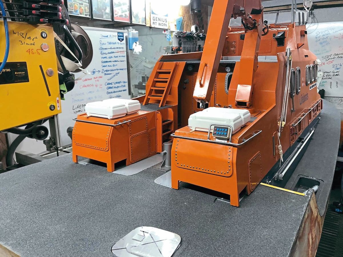
The life raft boxes I made from plywood frames and plenty of filler, with the cradles they sit on being made from aluminium. I used blue ribbon for the webbing and made the D rings from some wire.
The handrails were next on the list, so I went to our local wire supplier and guessed at how much I would need. I paid about £30 and hoped I would have some left over when the model was finished.
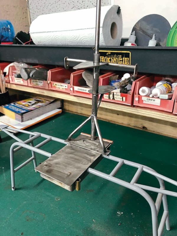
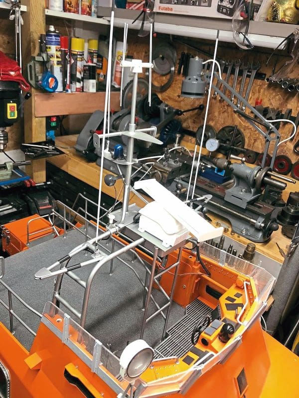
The handrail wire was bent in a vice, and it didn’t prove too difficult to follow the cabin and get the shape right. The hardest part was keeping the pieces aligned to solder and I made some mistakes, so had some reject pieces. These, however, I was able to cut up and use for smaller pieces. I also looked at the gantry I had made earlier. I wanted a metal mast as it would be stronger for all the detail I planned to add. I overheated the first one I made, though, and the brass melted, so I had to scrap it off. With its once bitten, twice shy replacement, I welded the baseplate and soldered the rest, and it all worked well. I also finished off the cabin handrails.
With the handrails painted and fitted I was able to start painting the gantry and mast, and to begin building the radar unit. For the latter I used an old servo and built the unit and scanner from plastic. I wanted the scanner to turn, and by varying the voltage it does so very realistically.
I made conduit from stretched springs inserted into heat shrink tubing, which I gently warmed up. I added some wiring too, so I could fit some lights to the mast. The weathervane I scratch built, adding as much detail as I could. The blue flashing light, flood lights, aerials and radar scanner all work, and the weathervane even spins in the wind.
For the cabin sides I made navigation light boxes, which light up green/red. All the wiring was fed into the cabin and connected to a distribution board, with switches fitted at the rear of the cabin.
I then put the cabin to one side so I could continue work on the hull. Having purchased two wheelchair motors, I made a cradle for these from metal and fitted them into the hull. Next, I cut out a hole at the bow for the bow thruster. The pipework was made from plastic waste pipe joints and glued into the hull, with filler added around the inlet/outlet holes, which I sanded back but left slightly raised.
Following this, I fabricated the engine cooling tubes, along with the hydraulic pipe box. The pipe box was made from scrap metal. For the cooling tubes I used copper pipe fittings, with covers made from brass. I also made up the trim tabs from brass and metal. The two smaller keels were made from 10mm steel. I needed the keels to be solid and strong as my idea was the model would be slotted into a simple stand. These were drilled and threaded so that they could eventually be bolted into the hull.
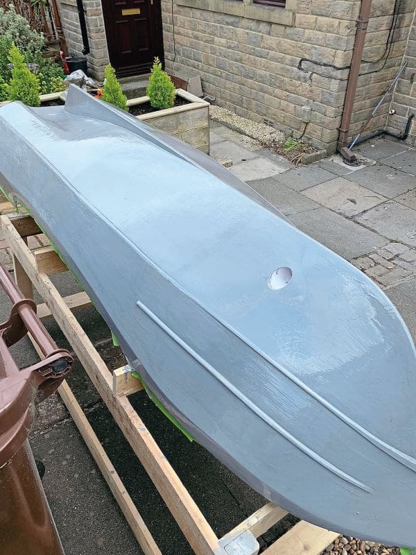
I then made a trolley and inverted the hull so I could wheel it outside to prep ahead of sealing it with polyester resin; this epic, but surprisingly relaxing – almost therapeutic, task involved three months of relentless sanding and filling. Naturally, I had to wait for a guaranteed spell of dry weather before applying the resin, which I’d thinned by 20% with acetone, using a brush. This soaked into the wood really well and, as the hull was out in the sunshine, dried fast too, so I was able to apply three thinned coats in one day. Following this, I added three more coats without thinning, and, once dry, wet sanded to get the hull really smooth.
Happy with the result, the next mammoth task was painting. I covered the entire garage in polythene and coated the entire hull in red Hammerite paint (smooth). This was done on the hottest day of the year, so the paint dried really quickly, although I still left it a week to fully harden before masking off so I could apply the blue paint.
I was finally able to slot the hull into its new stand and put the cabin back on so I could attach the rubber fender around the hull.
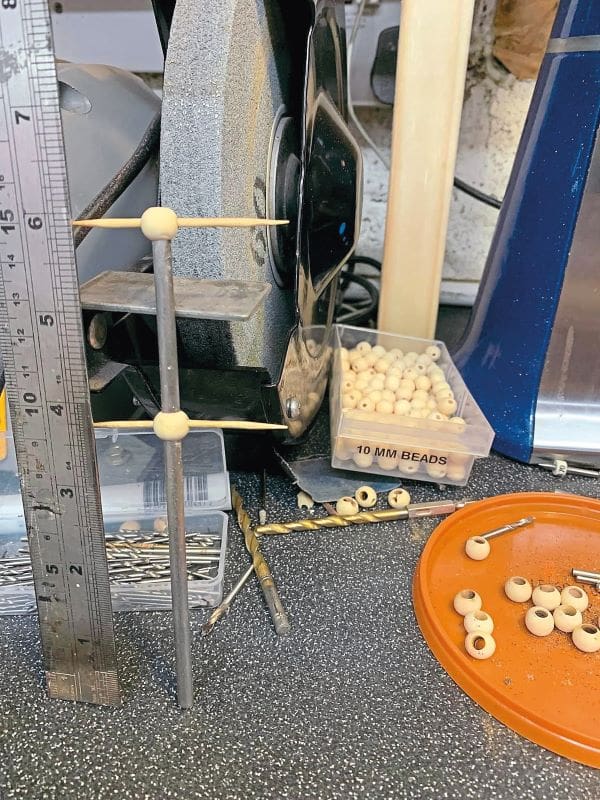
Once I’d added the exhausts and hydraulic box to the stern, my attention turned to making the handrails. I purchased about 30 meters of 5mm steel rod and spent the next few weeks cutting and bending, then soldering up. The stern rail has a rope guide in the middle and this piece had me head scratching, as it was hard to figure how to make this. In the end, though, it turned out great. I cut some brass strips and soldered these up, too. The stantions were made from the same 5mm metal, with a 1mm hole drilled in the middle and wood beads added. Having completed all of these, I painted them up and attached them to the hull. The rail attached to the front cabin is detachable to aid removal of the cabin.
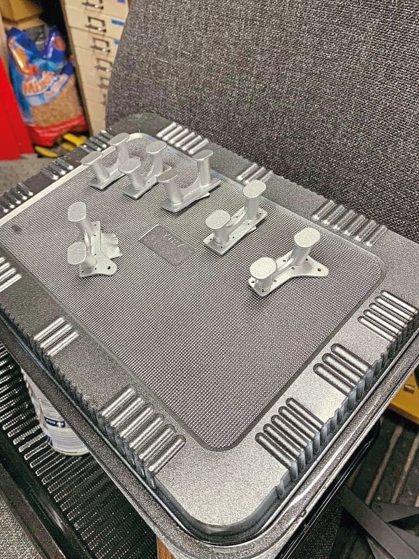
I then began work on with deck fittings, etc. The bollards I made from metal and soldered up, like the handrails, and the V bollards were fabricated from plastic out of the off-cut bin before being painted with metallic silver and clear coated.
Likewise, the anchors were made from scrap metal and soldered up, while the anchor station was constructed from the plastic and metal off-cuts, as were most of the other fittings.
Nearing completion
At the time of writing, I still have the propellors to make. I’ve saved this task for last, as I think it will be a long complex process. In the meantime, I am still continually adding to the detail and touching up the paintwork. After just over three years of building, I now envisage this model will be fully finished by early 2024.
Crew support
Building her has been a very steep learning curve but I’ve had great support, both from my wife and the crew from the Christopher Pearce, who contacted me after seeing I was attempting to build their boat.
‘Cardboard man’ blog
I began a Facebook build blog from day one, and have now uploaded hundreds of photos, so if you’d like to see more of the building work in progress and also the completion of the boat, search ‘Cardboard Man Model Boat Building’.
Cardboard Man? Well, I thought I should give a nod to the 1:8 scale cardboard man I use now and again to check what I am making looks to be the correct scale.