Richard Simpson embarks on a two-part build review of this 1:12 scale kit, aimed at the ‘Advanced Beginner’.
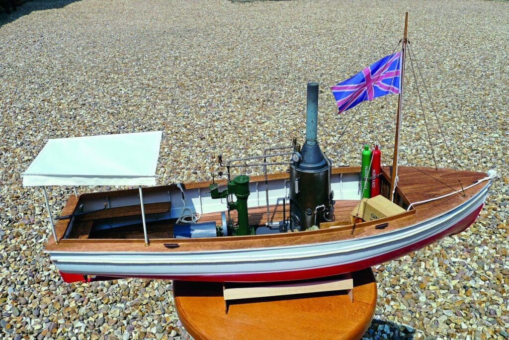
One of the things we actively pursue and promote is trying to attract more newcomers, particularly youngsters, into the hobby. To encourage this, I’m a great advocate of recommending a kit, both as a starting point and as a means of learning new skills, which can eventually be carried forward into more demanding projects. The beauty of kits is that, as they come with all the design in place, you can simply concentrate on the build, safe in the knowledge that, provided you follow all the instructions, there is every chance of a good outcome. So, when Billing Boats asked if someone would like to build and review its kit for the African Queen (see Photo 1), it seemed like an ideal opportunity to put my preaching into practice.
At the same time as I agreed to build the African Queen the editor also asked if I would like to evaluate some new Humbrol products. Consequently, all paints, varnishes, pigments and washes used in the build of my African Queen were from the current Humbrol range.
Enjoy more Model Boats Magazine reading in the monthly magazine.
Click here to subscribe & save.
Opening the box
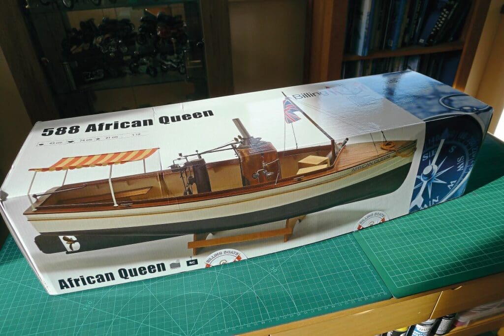
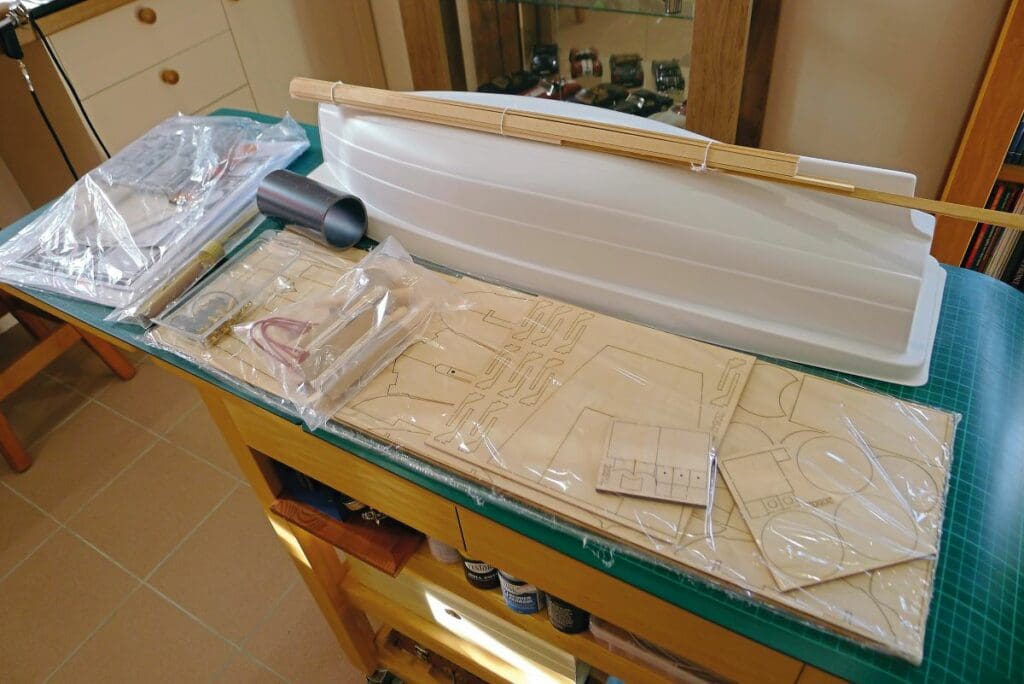
On receiving my review sample, and after the substantial packaging was removed, I got my first view of what I was letting myself in for. The box top depicted a large photograph of the prototype build, beautifully put together and looking very smart indeed (see Photo 2). Opening the box revealed a set of instructions, including a parts list, a full-sized drawing, wood strip, engine components attached to polystyrene sprues, various brass fittings and fixtures, a sheet of copper plate, a vac-formed hull, several laser-cut wooden frets and brass tube and rod (see Photo 3).
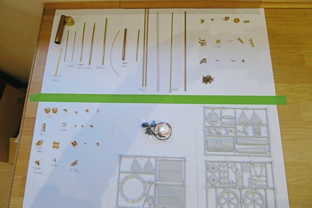
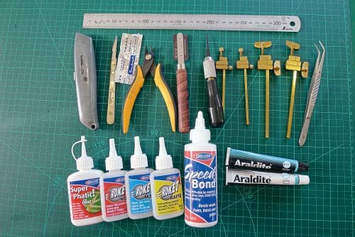
When presented with a bag of brass bits and pieces and bundles of varying stock material, I find it invaluable to separate all the parts and place them on a piece of paper. They can then all be measured up, identified and their respective part numbers recorded on that paper; you can also scribble down any notes you might find useful (see Photo 4). Being a fictitious vessel, research included finding and downloading stills from the movie and studying them. What immediately became apparent was that there were a few small variations between the model and the movie version, so I had some decisions to make. Should I follow the kit’s instructions to the letter, or should I aim to faithfully replicate the boat as she appeared in the movie? I opted to go for a bit of both. For authenticity’s sake, I decided to paint the engine green and the hull’s lower part red. However, while the vessel in the movie is absolutely filthy, from one end to the other, I didn’t want this to be a weathering demonstration. I decided, therefore, to follow the kit manufacturer’s guidance, reassuring myself that I can always – and, indeed, probably will – give this model the full weathering treatment at a later date. I chose to include the flag and awning that come with the kit, despite not spotting these in any of the movie stills I’d viewed. To get a better feel for the project, I also bought a copy of the movie and watched it. Matinee over, and with everything laid out and tools, glues, etc, readily to hand, it was time to make a start (see Photo 5).
A brief word on glue
One of the biggest challenges when working with vac-formed plastic is finding the right glue. In most cases the plastic is of a polystyrene type, so the best product for the job is a glue that will dissolve the surface of the plastic, thereby facilitating the bond process. This is fine for adhering plastic to plastic, but not quite so straightforward for plastic to wood joints. My first ‘go-to’ glue for any tricky joint is usually a two-part epoxy such as Araldite, and I used this to start with, until I discovered to my horror that the glue simply peeled off the plastic hull once it had cured. So, after asking around, I went for a tube of Stabilit Express. This is a very good, albeit extremely expensive, two-part glue, which creates an incredibly strong bond and sticks most things. A test run on a scrap of the hull’s plastic looked promising. However, I quickly realised that when it came to gluing the deck on, it was going to take a lot longer to get the glue around the top of the hull and the bulwark stays than the five minutes I had before the Stablit Express would start hardening. I came to the conclusion, therefore, that polystyrene cement was going to be my best bet – although this couldn’t be a thin variety. If the cement is thin, as with Liquid Poly or even Revel Contacta in a bottle, it soaks into the wood and evaporates before it has the chance to dissolve the surface of the plastic, so you end up with a very weak bond. The only glue that will work is the old fashioned thick polystyrene cement that you get in a tube. Even so, you must be careful not to use too much glue as there is always the danger of this dissolving its way right through a very thin plastic hull. For all wood-to-wood joints I used simple PVA white glue, whereas all brass components were glued with either cyanoacrylate or two-part epoxy.
Lower hull internals
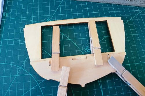
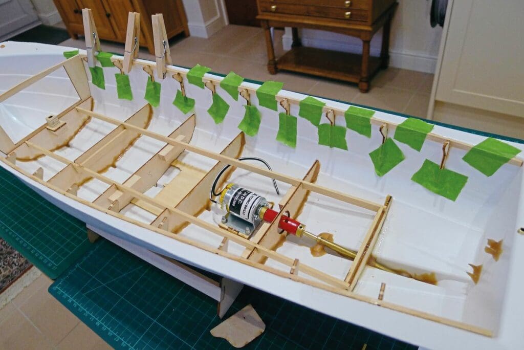
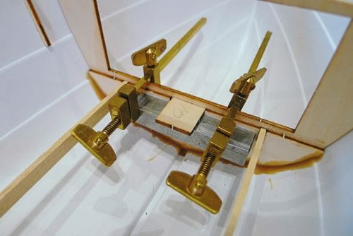
I decided that the best approach with the hull internals was to make the below deck frame and the two assemblies of upper frames and deck support as separate assemblies on the bench. This made keeping everything square much easier while the glue set. These parts were then fitted into the plastic hull as assemblies and glued with Stabilit Express. The forward main bulkhead was glued in first after laminating it with the below deck bulkhead (see Photo 6). As everything else is located from it, the positioning is critical. It also determines the positioning of the frames on the longitudinal strake, so has to be secured in the boat before the side frame assemblies can be made (see Photo 7.) Being a combination of wooden strip and laser cut ply didn’t present any problems. As I had tested a couple of joints without sanding off the dark burnt brown laser-cut edges of the ply and found that it glued securely, I didn’t bother sanding the edges off, as there is always a danger of making the joint sloppy by doing this. The below deck framing went in neatly and a substantial fillet of Stabilit Express was added to the edges of the bulkheads. This was closely followed by the frame assemblies.
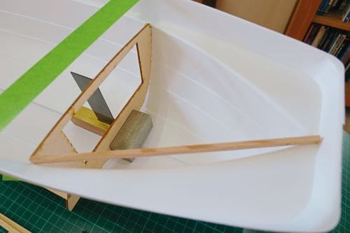
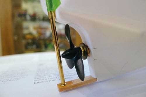
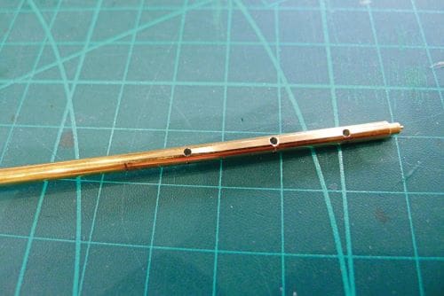
During this process, the motor, shafting and rudder assembly was also looked at for the best approach. Using the provided motor base, shaft and stern tube should fit in according to the plan; you still, however, want to try and achieve perfect alignment (see Photo 8). One aspect that did require some careful consideration was the rudder tube. This should be attached to the transom but that puts it at an angle with the keel line, and therefore the rudder bush inserted into the keel extension is also at an angle to the rudder stock. I wasn’t convinced that the keel extension was strong enough anyway, being a ply part, so I made my own from a scrap of pine. This was then drilled at a slight angle to take the rudder stock bush. With the rudder tube and propeller shaft all temporarily fitted, it did become apparent that there was very little clearance around the propeller (see Photo 9). Everything was held in place with tape to ensure a perfect fit before finally being glued in securely. Because of the tube arrangement, the rudder needs to be fitted after the stock is inserted in the tube, which is a little tricky, as gluing it straight to the brass shaft wouldn’t achieve a secure enough bond. Having pre-drilled the shaft (see Photo 10), my rudder was drilled and pinned once fitted.
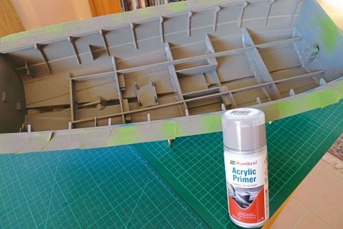
I was very careful with the cutting of the hull as I wanted to ensure my stern tube and keel extension penetrations were as neat and as accurate as possible. These parts were then filleted with plenty of Stabilit Express to seal and strengthen the areas. Finally, the main ballast component, the battery, needed locating. The instructions showed the battery mounted longitudinally; there were, however, bulkheads in the way, so my initial thought was to mount it transversely. I wasn’t happy, however, with the fact that, with no ballast at the ends, this could, potentially, make the model a little ‘bouncy’, so I went back to a longitudinal fit and decided the bulkhead would have to be cut. After the battery area was boxed off with a couple of longitudinal ply bulkheads to replace the lost strength, the battery sat neatly and securely along the centre line (see Photo 11). Once all the internal hull parts were in place, including the mast socket base (see Photo 12), the gluing surfaces for the deck were then masked off and the internal surfaces were given a couple of coats of Humbrol acrylic primer (see Photo 13).
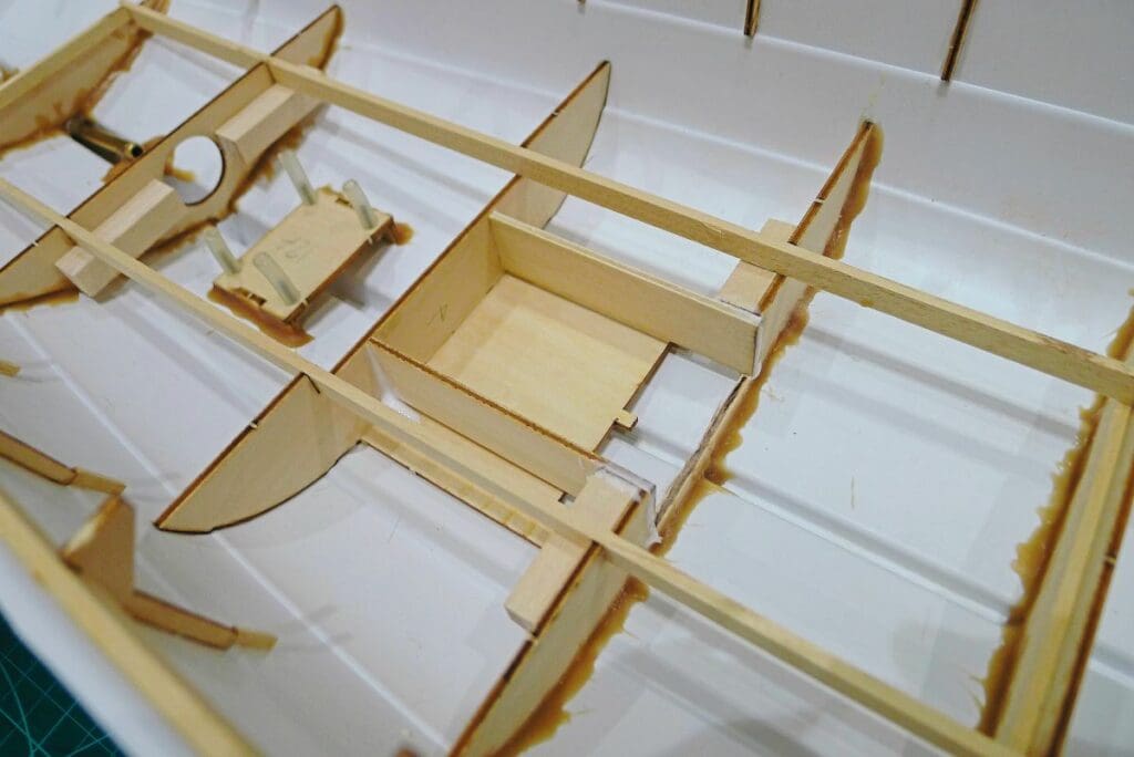
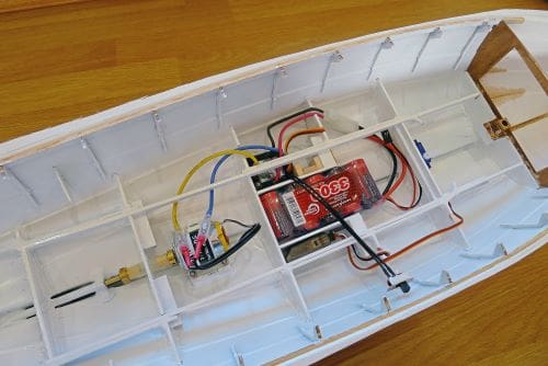
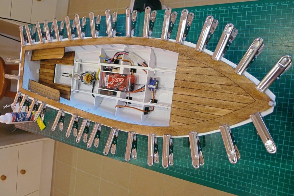
With the lower framework and motor in place, it was then possible to see the space available for the fitting of the electronics. I had chosen to go with a 3V to 7.2V 380 brushed motor, as recommended, and run it at 6V, deciding, as the model is particularly light, this would be plenty of power. I wanted a morning’s duration though, so I bought a 3300mha, five cell Nimh pack, a Spektrum receiver to use with my Spektrum transmitter, and an Mtroniks Viper speed controller. The instructions showed the steering servo in the forward locker, which I really didn’t like. This would make access extremely difficult and require the removal of the mast and forward bulkhead hatch just to see the servo, and actually getting to it would still be impossible. I decided, therefore, the best location would be below the deck, where there was just enough space for a micro servo to be mounted. Linkages would be lengthy and complicated from this location though, so I decided to use a couple of fishing lines run through copper tube to operate the rudder via the tiller arm. This proved to be neat, easily accessible and moved the rudder positively. The copper tube was simply glued in place (see Photo 14) to enable the fishing lines to be tied to an eyelet below the tiller arm before being secured with a copper thimble.
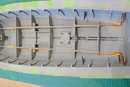
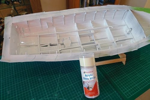
With this finished, another coat of primer was sprayed onto the copper tubes before all internals were given a couple of coats of acrylic gloss white (see Photo 15). The electronics were then fitted and tested, and cables neatly tied up out of the way (see Photo 16)
The decks
I found work on the internal decks all pretty straightforward, these simply needing to be cut from the plywood frets and have planking drawn on with a black ball point pen before a thin brown enamel wash applied. The trickiest part was around the edge of the foredeck and the internal bench seats, where I had to draw a curved line parallel to the edge of the wood. I taped the pen to a pair of dividers for this. Alternate planks were given different numbers of strokes with the brush to make them look a little more individual. The deck surfaces were then finished off with a coat of matt varnish. The internal decks sat very neatly on top of the framework, with just the aft piece glued permanently in place. The hatch over the coupling was improved with a couple of beams to the underside to ensure it located neatly between the bulkheads when fitted, and the bench seats were given the same treatment before being glued to their brackets on the hull.
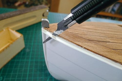
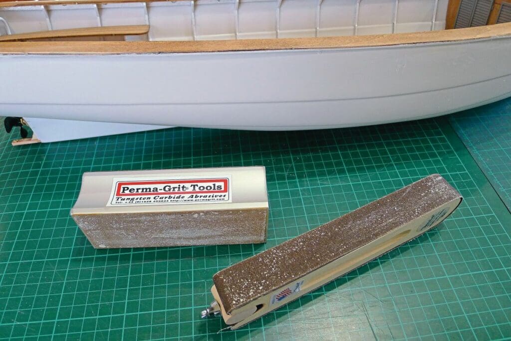
The fitting of the main deck was probably the biggest challenge and the process I put the most thought into. I knew, as it was cambered, that it would require holding down all around the edge. Locating it longitudinally would, I decided, make things significantly less troublesome. To achieve this, I fitted the top of the stem post into the vac-formed hull (this sits a lot easier if the front edges are chamfered). Once the glue had set, I applied modelling putty around the point of connection, which was then filed and smoothed until it seamlessly blended in with its surroundings. The main deck has a notch at the front end that sits around this post and the post has a step in it to locate the deck, so, if you get the stem post height right, you can slide the front of the deck into it, and it will be perfectly located. At the stern, the decking overhangs just enough to partly cover the rudder tube. I specifically left this a couple of millimeters proud of the transom for this very reason. Now I was able to cut a semi-circular notch into the aft end of the deck, which sat neatly over the tube, and this located the aft end of the main deck as well. So, with both ends of the deck located, all I had to concentrate on was clamping the edge of the deck around the top of the hull. The process involved laying a generous bead of polystyrene cement around the flat part at the top of the hull and then a bead of PVA white glue around the deck support and the top faces of all the frames. The deck was dropped on, and the edge clamped all the way around, ensuring there was a visible fillet of cement around the joint (see Photo 17). I then left it to fully cure for a few days. Following this, the clamps were removed, and the edge was trimmed close to the rim of the deck with a backwards cutting saw to ensure that no pressure was applied to open the joint (see Photo 18). Finally, the edge was finished off with abrasives to give a nice, neat edge to the deck (see Photo 19).
Hull exterior
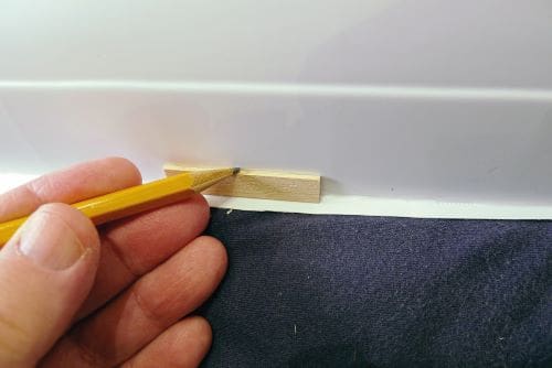
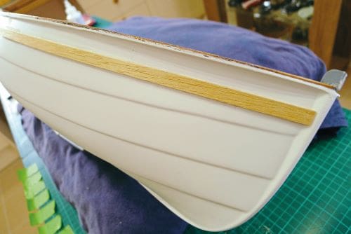
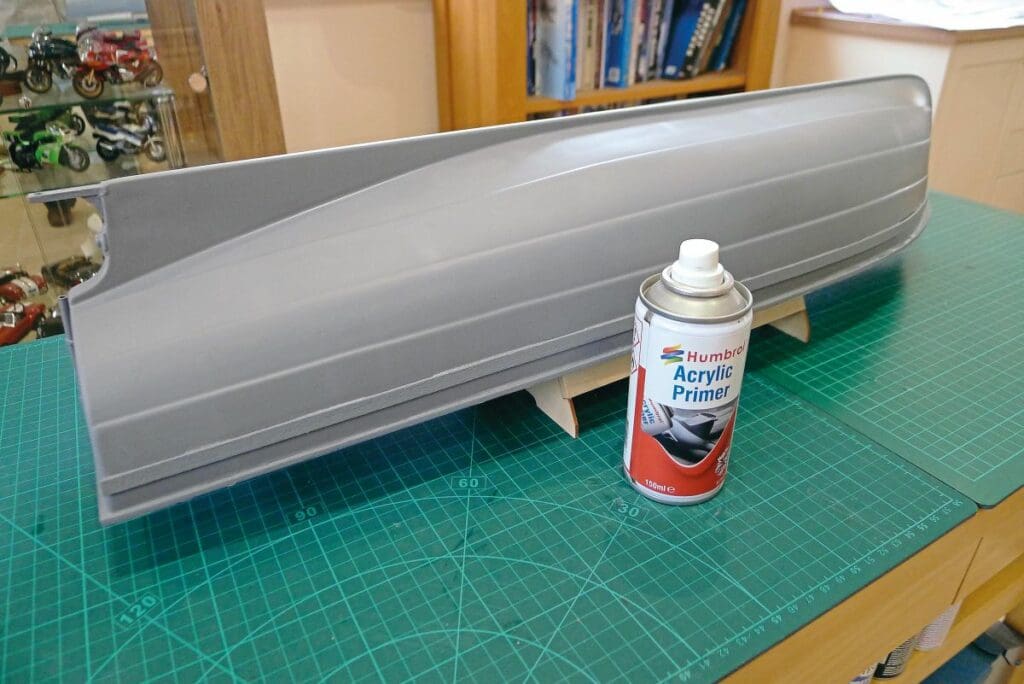
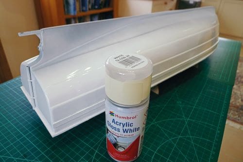
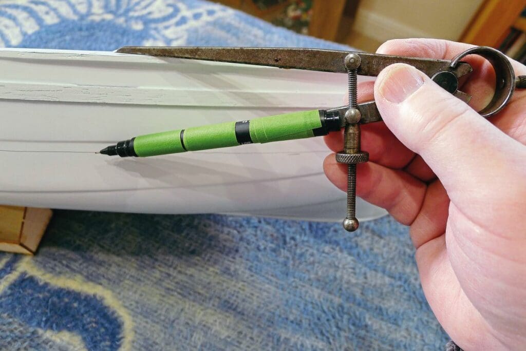
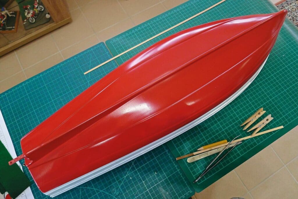
Externally there is very little on the hull, apart from a wooden rubbing strake that has a rope fender mounted on it. Having first marked the hull with a scrap of wood to determine the position of this strake (see Photo 20), I then glued it on with Stabilit (see Photo 21). The rudder was simply glued onto the rudder stock, after filing a groove in it (to better locate it), before being drilled and pinned though the rudder stock via the pre-drilled holes. The hull was then given a couple of coats of primer (see Photo 22) before I applied a white gloss coat to its upper surfaces (see Photo 23). Rather than being painted up to a waterline, the lower hull was to be painted up to a line parallel to the top of the hull, so this was marked out with a pen, again, attached to a pair of dividers (see Photo 24), then masked and sprayed with Humbrol gloss red below this line (see Photo 25). Finally, the rope fender was whipped at either end before being attached to the strake with thin cyanoacrylate glue.
Part 2
With the basics of the hull complete, stay tuned for part 2 covering the fitting out and completion of this model.