The Ernest Bazin was an unconventional, unsuccessful 19th century ‘Roller Ship’ – and when it comes to building the bizarre, modeller Lionel Broadbent is on a roll!
As a modeller attracted by the unusual, while recently pondering my next project I came across the Ernest Bazin, a subject even more curious and quirky than my round Ironclad Vitse-Admiral Popov (see the April 2022 edition of Model Boats). Now, if I proposed you build a model of a vessel that was square, with six wheels, a screw and sails, what would you say? I’ll forgive you that one! I, however, was absolutely fascinated by the concept, and decided this was a challenge I just couldn’t overlook.
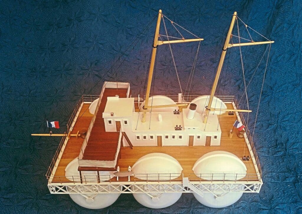
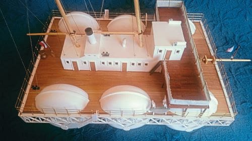
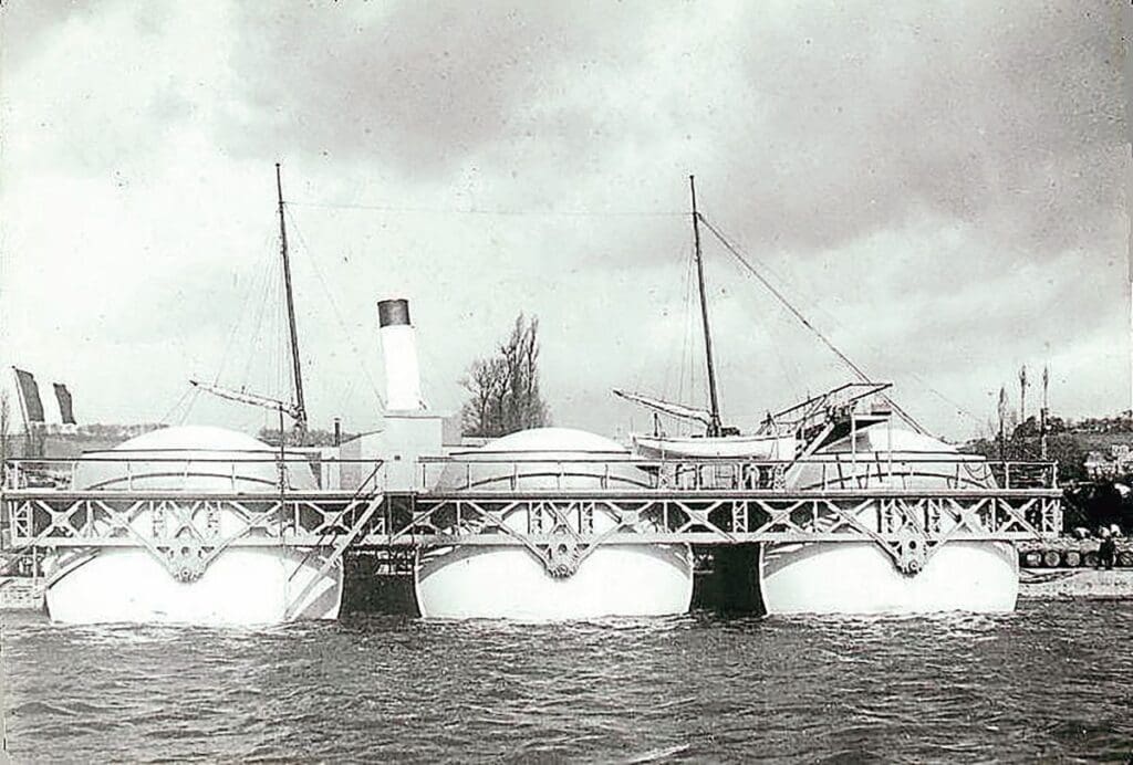
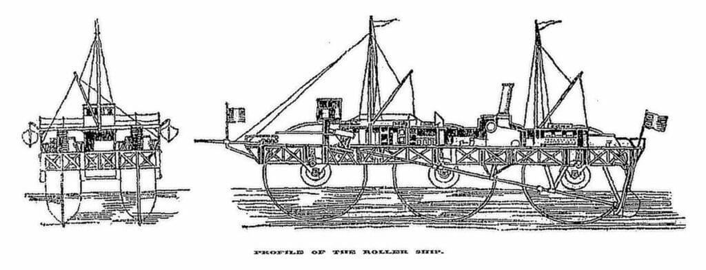
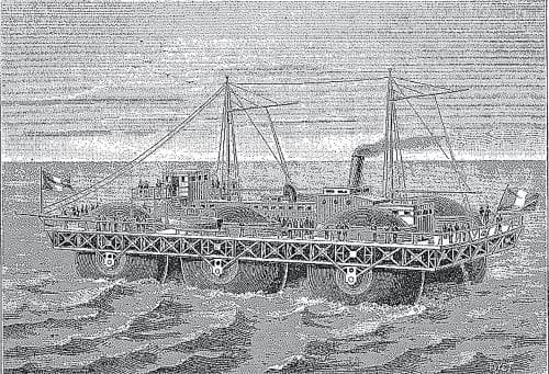
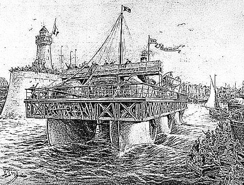
This ‘Roller Ship’ was an unconventional and unsuccessful of the late 19th century, intended to be propelled by means of large wheels. The first and only operational roller ship ever built, the concept for the 280-ton Ernest-Bazin was conceived by the inventor Ernest Bazin. After five years of model-based tests she was finally launched at on August 19, 1896. She featured three pairs of discs that were ten-metres in diameter and three-metres thick. Each pair was independently driven by a 50-horsepower engine while, under normal conditions, being about one-third submerged. The main hull was supported just above the axles of these discs, four metres above the sea level, and measured about 40 x 12 metres; this contained the engines as well as the crew housing.
Enjoy more Model Boats Magazine reading.
Click here to subscribe & save.
I do like researching the ships that I am keen to build, and this is a fascinating vessel. If you’re interested, there is much more information available, particularly on Wikipedia.
Getting the project rolling
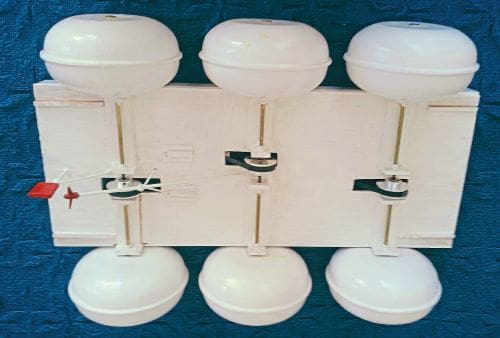
As with the Vitse-Admiral Popov, with no plans available (or at least none that I could find) I had no other choice but to start from scratch, working purely from photographs and measurements provided on Wikipedia (a valuable source of information, and I do contribute). Bearing in mind I would need to scale down to a model that would fit in my car (measurements of the actual ship and the model are included in the specifications box within this article), I started with 6-inch diameter rollers.
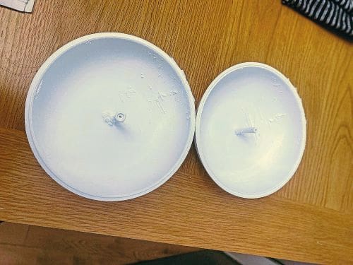
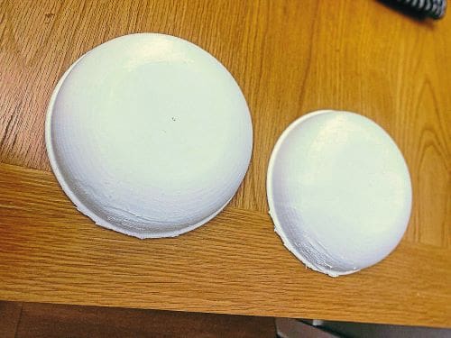
My first problem was creating those rollers. Initially I tried sticking two Chinese rice bowls together. This might have worked but, unfortunately, I couldn’t find enough identical shaped melamine rice bowls, and any other material would have proved too heavy. I then tried using one of my bowls as a fibreglass mould from which I could cast more in a similar shape. I would have had to make 18 halves in order to have sufficient, as I needed six complete rollers and six half rollers (to use as deck covers for my rollers). My attempt with fibreglass, however, wasn’t too clever, so I gave that a miss. Eventually, I decided to go down the 3D-printed route. The cost wasn’t too bad, actually: buying 18 rice bowls would have cost almost as much.
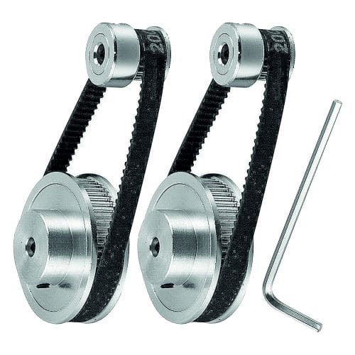
The second problem was the drives. I had to drive three double-sided rollers and one screw. I thought about double-sided drive motors linking each side to one roller. After struggling with the linkages and realising that the motors would have to be below decks and subject to water spray, though, I rejected that idea. I then discovered some ‘Synchronous Wheel Stepped Motor Pulley Reduction Gears’. Not only did these look ideal (the drive would be above deck) but they would also reduce the speed of the rollers’ motion. The main drive is a three-blade screw, so I needed to drive three pulley gear motors and one screw motor.
A tale of two halves
Having solved the drive problem, I decided to build the ship in two parts. The bottom part would incorporate the drive deck and electronics, while the upper part would consist of the main deck, superstructure and furniture. This meant that a simple removal of the main deck (with all its furniture) would give me clear access to all the mechanics and electronics below. Just a matter of measurements!
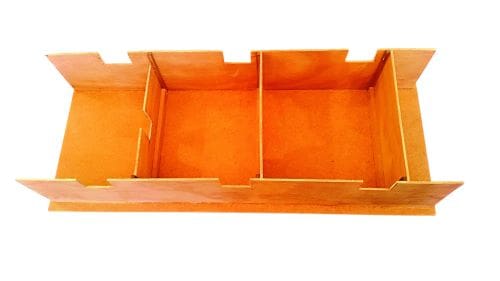
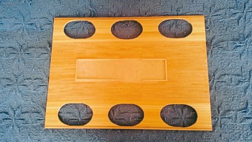
All about the base
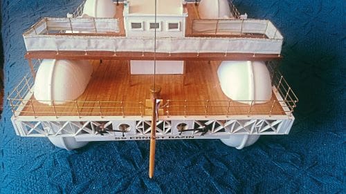
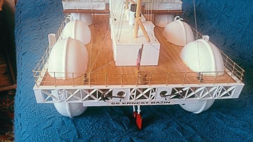
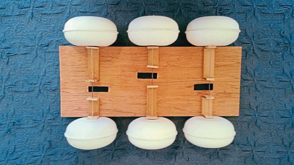
Because the ship had no proper keel, I had to design and make a base for it to sit upon to allow the suspension of the rollers, the main drive shaft and the rudder shaft.
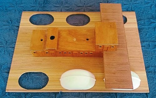
In order for all the motors to fit in, I had to stagger the roller motors, so, two motors rotate clockwise and the third, along with the propeller, rotates anticlockwise.
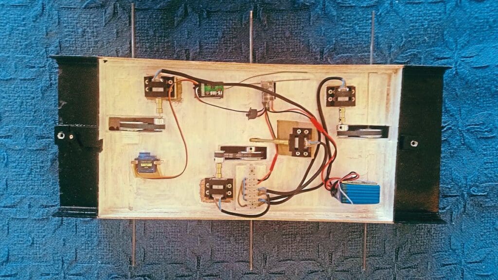
Connecting the drive shafts to the motors and to the rollers wasn’t easy. I initially tried 2mm drive shafts. Unfortunately, not only would they not fit the gear pulleys, but they didn’t have enough strength – they flexed slightly. I therefore opted for 4mm shafts; this meant re-boring the rollers. These also didn’t fit the gear pulleys, so I had to add another tube and use Araldite to fix them to the pulleys. I also used Araldite to adhere the rollers to the outer shafts. I sealed both sides of each roller with washers, making sure they were leak-proof; after all, the six rollers are what the ship floats on. The cross supports for the screw shaft and the rudder shaft were fashioned from a wire coat hanger; it’s amazing what a bit of improvisation can do!
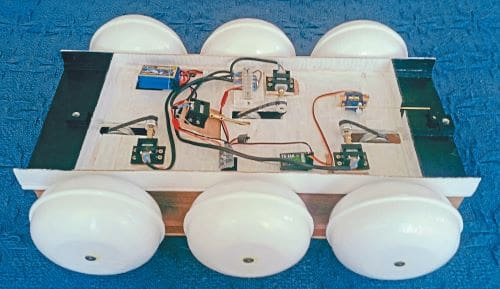
With the drive deck complete with rollers and electrics, it was now on to the main deck and superstructure.
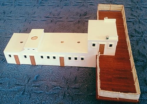
Building the upper main deck
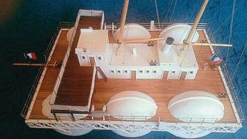
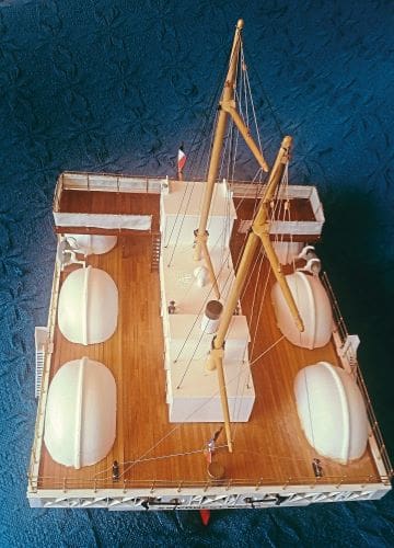
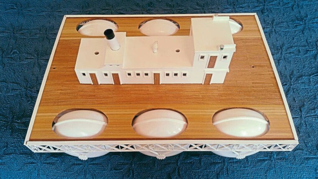
In building the upper main deck I had to provide six openings for the rollers to pass through, with sufficient room for the bridge, roller covers and cabins.
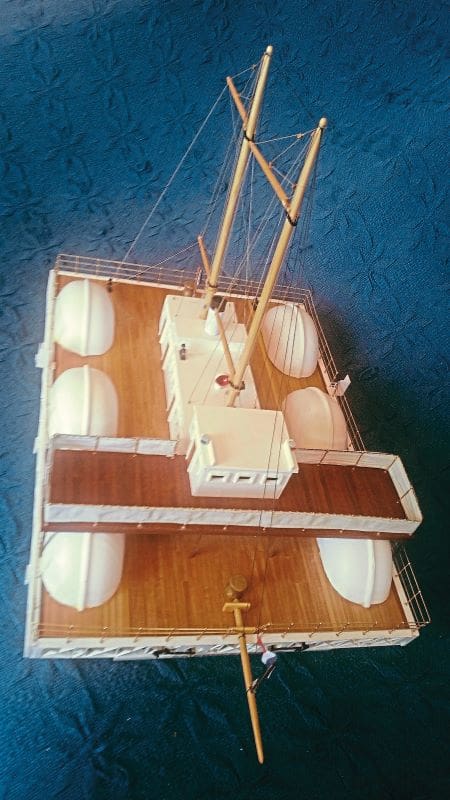
The flying bridge has a canvas surround; this meant a bit of work with the old sewing machine (thank you, Mom, for those early lessons!).
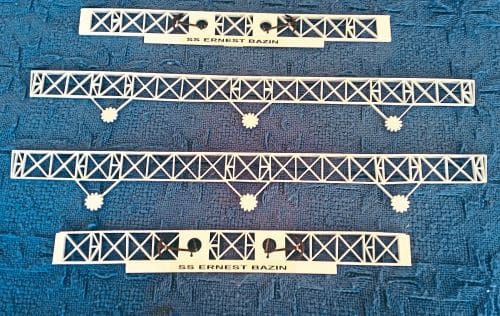
The upper main deck features a lattice surround. Crafting this was a bit fiddly, but I had plenty of strips of wood left over from previous models and once painted up I was pleased with the result. Amazingly, although made of glued wood strips, the lattice proved to have great strength when fitted. The roller shafts do not connect with the lattice supports; this enables me to remove the upper main deck from the bottom drive deck for easy access to the motors and electrics. I disguised two bolts as large bollards fore and aft to attach both decks securely. All surfaces were sealed and either painted or varnished for water protection.
Performance
The model floats well; a little lower than I expected. This is probably due to changing the main deck from 3ply to MDF – a bit heavier but more stable. The rollers work, but I experienced the same problem as Bazin, in that they don’t help much in the craft’s forward motion – in fact, the faster they turn the more drag they create; steering also becomes a problem, because no speed equals no motion, and no steering!
Rigging
The rigging I’ve used is shown in one of the pictures on Wikipedia: a kind of gaff-ketch rig, more commonly referred to as the ‘Dandy Rig’ – an efficient type also used by the schooner America in 1851. The addition of sail rigging was obviously an emergency back-up in case of power failure. However, having experienced ‘Blue Water’ yacht racing, I would hate to think how this vessel would have behaved under sail in the Atlantic Ocean. I am sure being non-operational the rollers would have been more of a hazard than a floatation device benefit!
SS or RS?
I feel this ship’s name, SS Ernest Bazin, is something of a misnomer. SS, for those of you who don’t know, stands for Screw Ship – not Steam Ship, as is commonly thought. So, as this vessel is driven by six rollers and only one screw, maybe it should be named RS ((Roller Ship) Ernest Bazin – just a thought!