A Beginner’s Complete Steam Plant
RICHARD SIMPSON reviews the Miniature Steam Models Clyde Engine and Boiler
Enjoy more Model Boats Magazine reading.
Click here to subscribe & save.
To see annotated photos for this article click here.
We had a brief look at the Miniature Steam Models three inch boiler and Clyde engine plant in Test Bench within the April 2012 MB, but now it’s time to see just what you get for your money and see how it performs in a bit more detail.
The Miniature Steam range
Miniature Steam is an Australian manufacturer producing a range of two, three and four inch vertical and horizontal boilers, associated accessories as well as a number of engines in various combinations and states of completion. The range includes all the accessories that you may require to put your own plant together, but this particular example here is a complete ready to assemble and fully operational steam plant on its own mounting plate. It is therefore almost ready to drop into any suitable model. This makes it ideal for a beginner to model steam as all the thinking and design has been done for you, but you still have the option of building the engine, cladding the boiler and putting it all together, so you will have a degree of satisfaction in personalising it.
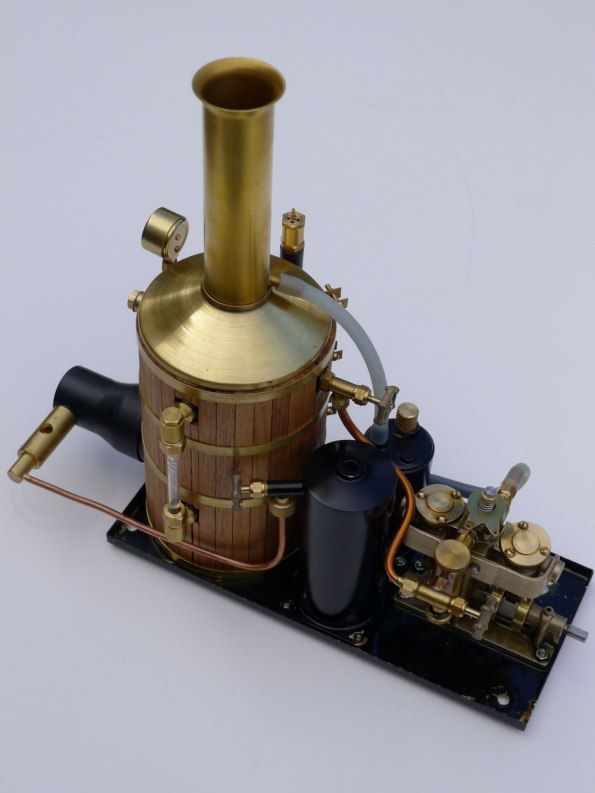
The steam plant as supplied for this review consists of a three inch vertical boiler, a Clyde Engine as a self assembly kit, a gas tank, separator, burner unit and a ready drilled base. Absolutely everything you need to put a complete working steam plant together as the engine also includes the lubricator and a steam regulating valve. So all you need to add are water, gas and oil, Photo 1.
Building the engine
First of all, the Clyde engine is similar in design, construction and dimensions to a number of other old, but no longer manufactured engines such as the Cheddar Puffin which has to be a good thing. As anyone associated with those engines is well aware, they have been known for many years as a lovely simple, reliable and robust engine, supported by the fact that many of them are still around today. This type of engine has powered many a model boat over the years, so to see a similar engine still in production, but utilising modern day casting and machining techniques and incorporating modifications such as the revised piston rod gland arrangement has to be a good thing. The casting quality and machined surfaces are of the highest standard and the engine looks good without needing to be painted.
Opening up the engine box revealed a very well packaged kit of parts, including all the pre-finished and machined components ready to assemble and a bag of screws, gaskets, springs and O rings, Photo 2. The only other items you will require will be a small flat screwdriver, small spanners for the pipe fittings and hex screws, plus some thread sealant. The Allen key you will need is included in the kit. The Clyde is a twin cylinder oscillating engine in an in-line configuration and as mentioned earlier, comes complete with lubricator as well as incorporating a built in control valve, enabling easy control of speed and direction of rotation on a single r/c channel.
The assembly of the engine is very straightforward and as long as you follow a logical sequence, you shouldn’t have any difficulty. The cylinder units were assembled first after applying liberal amounts of engine oil and using the very neatly cut gaskets provided. The piston O rings were also oiled and carefully pushed into the cylinders taking great care not to nip them in the process, Photo 3. I would normally advocate a light lapping in of the cylinder port faces before putting them together, however the pivot pins were pre-fitted and as I didn’t want to remove them, I decided to trust to the finished faces as supplied and see how they bedded in together.
Next to go together was the crankshaft assembly, which is of a simple fabricated construction involving sliding the relevant shafts through the housing bearings and nipping the flyweights to the shafts with the grub screws located in the weights. Try to adjust the parts of the crankshaft to take up any longitudinal float and maintain a consistent location of the shafts in the bearings, Photo 4. Once the crankshaft is assembled, the cylinders can be placed against the port faces and the cylinder holding bracket put in place against the main engine trunk while you carefully insert the springs into the cups on the end. Once the springs are in the cups and located in the indentations in the cylinder castings, the cylinder holding bracket can be screwed to the engine trunk. Inserting the springs is best done with the aid of a small flat bladed screwdriver to compress them as you get them into place. When the cylinder holding bracket is screwed into place with two of the hex headed screws, the next step is to fit the control valve. Again, oil should be applied to the surface first and the final hex headed screw should be fitted to the spacer and the last spring before fitting this through the valve and screwing it to the threaded hole in the top of the engine trunk. Don’t make the mistake of leaving this slack, as the screw should be tightened down to prevent the valve from coming apart in use.
Finally, fit the lubricator to the inlet side of the engine and the exhaust fitting to the exhaust side of the engine using some form of thread sealant such as a paint on paste or PTFE thread tape, Photo 5. The last task is having a smile and treating yourself to a cup of tea! I assembled the engine in less than two hours and that was being particularly careful and meticulous, so it is not a difficult process and certainly well within the capabilities of a beginner to model steam.
Running in the engine
The next step was to start the running in process with compressed air. I always like to run an engine for at least a couple of hours on air to start the bedding in process before committing it to steam, all of which I find more convenient. The main consideration with this process is the fact that the displacement lubricator does not work with compressed air, so manual lubrication of the engine is necessary. This can be achieved with a syringe into the supply pipe or removing the control valve and placing a couple of drops of oil down the ports. I start with as low a pressure as possible to start the engine turning, then turn the pressure up during the process. The Clyde boiler has a working pressure of 60psi, or 4 bar, so running in on air should be easily achievable on around half of that. If you don’t have access to a compressor, an old inner tube can easily be rigged up to provide a supply, but I suspect that most modellers will have some sort of airbrush compressor that could be used, Photo 6. Take care not to over-use airbrush compressors as many are not rated for continuous use and don’t be tempted to use small gas canisters as they cool significantly when in continuous use and can lead to condensation in the air lines which will cause wearing out rather than running in! The engine should be oiled every ten minutes to start with, which can be reduced as you get towards the two hour period, with the Clyde being particularly easy as it is so easy to remove the control valve, pump some oil into all the ports and replace the valve before starting again. Don’t forget to turn the air off first though!
Don’t forget as well that if you ever decide to run the engine on air in the future, another means of lubricating the engine than the displacement lubricator must be considered.
I was surprised initially at how tight the engine seemed and at how reluctant it was to start and reverse. However after a couple of hours it had bedded in beautifully and I was able to start, reverse and run the engine on very low air pressure. Everything was then disassembled, cleaned, lubricated with steam oil and finally reassembled before fastening to the steam plant base.
Cladding the Boiler
The vertical three inch boiler comes as a complete pressure shell with proper certification, but there remains the option to clad it with the supplied wood and banding, Photo 7. This gives a degree of personalisation and satisfaction, as well as making the plant that little bit more practical to operate. Many would recommend putting a layer of insulating cloth around the boiler before the cladding. However I wanted particularly to assemble this plant straight out of the box and I’m not sure whether the addition of insulation is really worth the effort for such a small boiler. Adding insulation might also require new banding to be sourced as the overall diameter would be slightly increased. There are also a number of different ways of applying the cladding, with the plant instructions advocating the use of superglue to attach the planks. I’m not keen on that method as the glue gives off quite a smell when the boiler is first fired up, as well as the fact that it is very unforgiving if you make a mistake and you would then have quite a job rectifying the error. I prefer to add the cladding using elastic bands to keep it all in place before fitting the brass bands to properly secure it, Photo 8. Any loose ends will be suitably held in place by the varnish, but these should be minimised by careful location of the banding. This method gives you far more flexibility during assembly and the opportunity to make small adjustments as you tighten the bands, Photo 9. I finished the boiler with a coat of polyurethane varnish to seal the wood and hold the one or two loose plank ends. The varnish of course has the added advantage of bringing out the lovely colour of the wood. Some would advocate the use of oil rather than varnish, but this would then require doing on a regular basis so I prefer varnish.
I was very pleased to see four brass bands supplied, complete with the fitting screws, which all slotted over the cladding perfectly. Even if you don’t think the boiler needs the cladding I would highly recommend that you fit it, as it significantly improves the looks and gives you a great deal of satisfaction by having some additional input into the steam plant, Photo 10.
Fitting the boiler and other components
With the cladding finished, it was time to add the boiler to the base with the supplied two set screws going through the base plate. I made the mistake of reversing the base so that the plant didn’t sit on the set screw heads, but then realised that the gas tank and separator would be on the wrong side, so I had to go along with the original design. The pipework supplied with the model is tailored to the designed layout, so care must be taken to ensure that the components are fitted correctly on the base. That doesn’t mean to say that the layout cannot be changed, but the great beauty of this design is that everything you need is mounted on the single base. This makes fitting and removal from the model extremely simple, so trying to maintain the designed arrangement is well worth the effort.
Next job was is fit the separator and the gas tank in their respective locations taking care to secure the separator with its screws, but fitting the screws and then sitting the gas tank on top of the exposed screw threads and then fastening it down. This enables the tank to be removed easily for refilling and it also prevents excessive heat transfer into the gas tank which would occur if it were mounted directly onto the baseplate, Photo 11.
With all the major components now attached to the baseplate, the final job is to plumb everything together and add the burner. The burner simply sits in the throat of the furnace so that is a very straightforward, however the burner setting instructions should be read before you fit it. The instructions state how to set up the burner by adjusting the nozzle position in the air tube before you actually place the ceramic burner onto the furnace front. This way you actually get to see that the flame is at its optimum performance before fitting the burner and ensuring the most efficient burning rather than trying to play around with it when it is fitted and you can’t see what is going on! When the burner is fitted, the gas pipe can be connected to the gas tank, the steam supply pipe can be fitted between the boiler outlet and the engine inlet and the silicone tube cut and attached between the separator and the engine exhaust and the separator and the exhaust pipe in the funnel. With the funnel and brass covering dish added to the top of the boiler, the entire plant is ready for its first taste of steam!
However, one final point. It is well worth testing the pressure gauge against a properly calibrated gauge. This would be a part of a normal steaming test and can be done by a club steam tester to ensure the accuracy of the gauge. In this case the gauge was spot on across its entire range, so was refitted to the boiler, Photo 12.
The first firing
The first job is to fill the boiler with water. So, remove the funnel, the brass dish and the filling screw, before injecting water into the boiler shell. I filled it to the top of the sight glass but ensured that the level could still just be seen and then refitted the filling plug and brass boiler covering dish. Next task is to fill the gas tank. Fit the filling nozzle to a can of 70/30 Butane/Propane mix and upend the can. The tip of the filling nozzle should be pushed firmly and quickly onto the top of the Ronson valve in the top of the gas tank and held firmly in place until liquid gas is seen escaping from the Ronson valve. The Ronson valve is fitted with a tube inside the gas tank to ensure that there is always a gas space above the liquid level in the tank. Finally the displacement lubricator must be filled with proprietary steam oil and the plant is ready to go. I would also recommend that you fit some form of linkage to the control valve horn as the valve will get hot when in operation and you will find yourself struggling to operate the valve at a time when you particularly need to. A simple bent wire linkage will work fine for now.
With the steam supply valve closed, the boiler should be lit from the top of the funnel, I found it best with the gas valve just opened to start with, then when the flame is established slowly open the valve further until a good roar is heard. The burner is actually very effective and brings the boiler up to pressure very quickly, so as soon as the pressure started to rise I turned the burner right down so that the pressure rose slowly as now it was the time to set the relief valve. The boiler working pressure is 60psi (4 bar), so when the pressure in the boiler has reached 4 bar the safety valve should be adjusted to lift, Photo 13. This is done by slackening off the locknut, then adjusting the valve by putting a pair of tweezers in two of the steam ports in the valve. Rotate the valve until steam starts to escape, then tighten the locknut again. It is then best to shut the gas off and let the pressure drop before reigniting the burner and slowly bringing the pressure up again. The safety valve should then start to lift at 4 bar.
Once you are happy with the performance of the safety valve, it is time to open the steam outlet valve on the boiler and the steam valve on the engine lubricator. The engine is now pressurised up to the control valve, so gentle movement of this valve in either direction will admit steam to the engine. This should be done with caution as there will be a slug of condensed water that has to go through the system first and which will almost certainly spit out of the valve and cylinder port faces before good quality steam passes through. When the engine settles down, operate the control valve backwards and forwards to seat the valve down and test the operation of the engine.
The Clyde engine proved to be very responsive across the speed range and settled down quickly to smooth and reliable operation. The biggest challenge at this point came from controlling the burner. The burner fitted to the boiler is very efficient and a good size, so it gives out a significant amount of heat. This produces steam at a rate higher than the engine uses, even when on full speed, so the pressure rises and eventually lifts the safety valve. The only option is to turn the gas down to give a lower flame, but once again, as the gas tank starts to absorb some heat from the surroundings, the gas pressure starts to rise once more and affects the burner, so it does take some time to settle down to a balanced condition where you have the burner set at a level that remains consistent and provides approximately the amount of steam you need for the engine. There are also a number of things at work here that play a part in this effect, such as ambient temperature, use of the engine and the amount of heat the gas tank absorbs from the surroundings. You may well find that getting things perfectly balanced in the workshop will not work when you take the plant down to the pond on a frosty winter’s morning, so this is perhaps one area that could be improved with a modification such as an attenuator valve (please refer to Boiler Room in MB May 2011). However, as it is, the plant is simple and compact and perfectly suited to the beginner who is looking for something that he (or she) can put straight into a model boat, Photo 14. Learning about the way gas behaves under varying temperatures and with varying demands on the boiler is a great way to become familiar with the intricacies of model steam plants and will lead the beginner perfectly into just what he may want to do to modify the plant to make operation that bit more efficient and user friendly. I also discussed the issue of heat transfer to the gas tank with the manufacturer who informed me that alternative arrangements for mounting the gas tank are being evaluated continuously, so the final market version may well be slightly different to this evaluation model.
On the water
I am very lucky to have a Krick Borkum fitted with an old Cheddar plant on the shelf that I have had for a number of years and which I decided would be an ideal test model for this Miniature Steam Models Clyde plant. The Cheddar plant was removed and the base drilled on the Miniature Steam Models plant before the flywheel was taken from the Cheddar engine and fitted to the Clyde unit to enable the dog clutch drive to connect. The plant was then dropped straight into the base of the Borkum and the engine control servo was connected to the control valve. The Clyde plant fitted the Borkum perfectly and showed just what a suitable unit this particular steam plant is for the Borkum and other models of a similar size, Photo 15. In a hull such as the Borkum, the Miniature Steam plant really shines as a and shows just how well this particular plant can be used with a relatively easy to assemble model boat kit to get a complete steam model up and running with current off the shelf gear.
The plant was filled with gas, water and oil, and the separator tank emptied before firing up the boiler at the pondside. This time instead of being in a warm workshop, the model was outside on a cold and frosty morning, so the boiler took a bit more care to light and there was more of a difference between the cold starting conditions and the warmer running conditions. So the plant was left for a while to normalise its temperature and allow the gas tank to warm before finally adjusting the gas valve to give a suitable flame. Then just a quick test with the r/c gear and the model was launched into the water.
With any steam plant that does not incorporate any control of its burner, as I had already discovered in the workshop, it is always going to be a challenge to match the heat input to the boiler with the engine requirements. When you add a cold morning to the mix to complicate things further, you find yourself either keeping the model moving for the sake of preventing the safety valve lifting, or finding it slowing down as the boiler becomes unable to keep up with the engine. Having said that, the plant is a great beginner’s plant with a simple and reliable engine, a beautifully made boiler and everything you need to get steam propulsion into a model to be up and running. The Borkum behaved perfectly with the Clyde plant fitted and happily manoeuvred for around twenty minutes before the boiler was showing low water in the sight glass. Pretty soon a routine of twenty minutes on the water before topping up the boiler, gas tank and lubricator as well as emptying the separator was established, and the plant proved to be reliable and easy to operate, Photo 16.
Conclusion
All in all, this steam plant is everything you need to get a practical engine and boiler into a model as an easy to assemble and operate complete package. It worked perfectly in the Borkum and shows just how straightforward it can be to get yourself on the water with a steam powered model. JoTiKa have informed me that their intention is that this complete plant is one of the first of a range of similar complete units of varying sizes to complement their models such as the Joffre steam tug and the Clyde Northlight puffer. These models will use a two inch boiler and will include tailored pipework and auxiliaries to perfectly match the steam plant to the model. If this first example is anything to go by, then they should make a perfect combination and enable first time steam modellers to buy the complete steam package and model boat kit from a single supplier who will also be able to provide support and advice to help the modeller.
Availability
JoTiKa are the exclusive European distributor for all Miniature Steam Model products and can be contacted on tel: 01905 776073. They will be happy to answer any enquiries that you may have. Their website is: www.jotika-ltd.com, email: [email protected]. Price is around £1040 complete, depending on current exchange rates.
All products distributed by JoTiKa Ltd. are available through the usual retail outlets as advertised in this magazine or via their own Model Shipwright online shop.