DAVE PETTS describes the construction of his WW2 German armed trawler
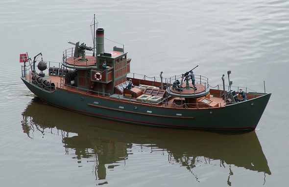
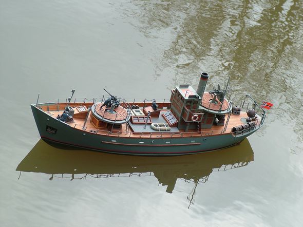
The completed model afloat
Following the completion of my last model I began looking around for another project and by chance ended up looking at the Kingston Mouldings website: www.kingstonmouldings.com. This manufacturer has quite a list of interesting models to build from their hulls, each of which are supplied with a plan. My attention was drawn to a converted German trawler called a Vorpostenboot which was used by the Kriegsmarine for the defence of coastal waters. There is in fact a similar vessel in the range but with a different stern layout called Hafenschultzboot, which was used for harbour defence. During the last war most nations commandeered civilian ships, very often trawlers, and then converted them to a military role to supplement their regular navies.
Enjoy more Model Boats Magazine reading.
Click here to subscribe & save.
The Vorpostenboot (Forward Post Boat) is an example of a civilian trawler that was converted for an anti-submarine and mine laying role for the German Navy during WW2. Another feature of this particular subject is that much of the construction involves wood, a material I really enjoy using, so you may call me old fashioned if you wish, but I like it.
Getting started
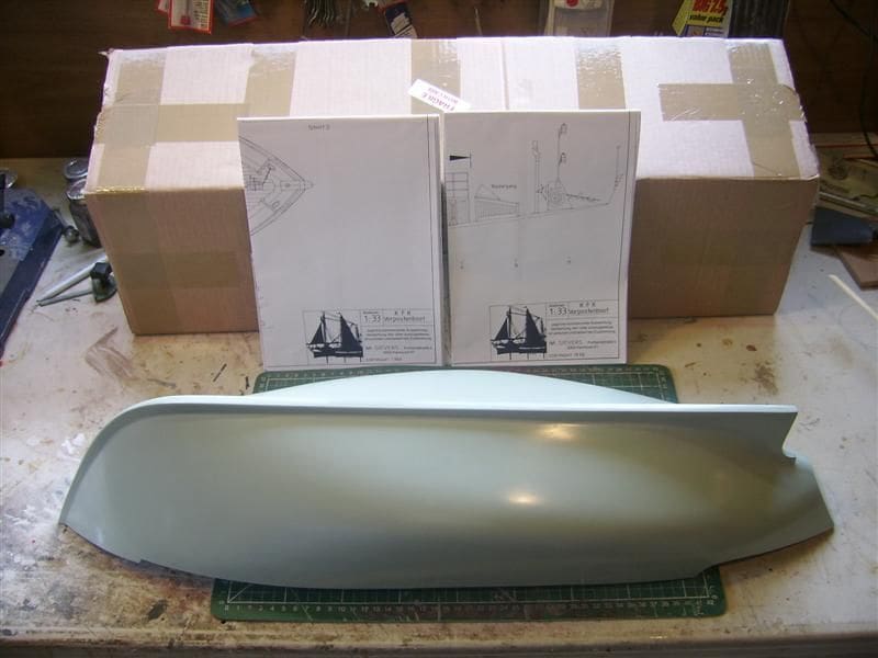
So the order was dispatched and within a short time a nice big box containing the hull and plans (on two sheets) arrived, Photo 1. Before proceeding further, let me say that the Kingston Mouldings GRP hull was excellent and held its shape firmly without the need for internal bracing. The written descriptions on the plan are in German, but they are obvious and you won’t need to undertake a language course to understand them.
Now a word of warning, or hopefully of encouragement, is that other than the hull and plan this is a model for scratch building, as the plans do not give any indication as to the access hatch positions, installation of running gear and control equipment or indeed any construction methods whatsoever. Therefore this is definitely a model to think about and is a modelling challenge, but having a good plan and a robust well moulded hull does make the task easier.
I decided to build the model as an example of such a vessel (semi-exact scale in MPBA terms) and had in mind a trawler whose holds had been cleared and covered over for crew accommodation. Also I decided to add a funnel as I wanted to include a working smoke effect on the completed model. Yes, not strictly correct as I guess the original was diesel powered and no funnel was shown on the plan, but some diesel powered vessels do have funnels and this was intended as a non-specific representation of this type of craft. Some of the fittings, including the guns were obtained from Waverley Models.
Hull preparation
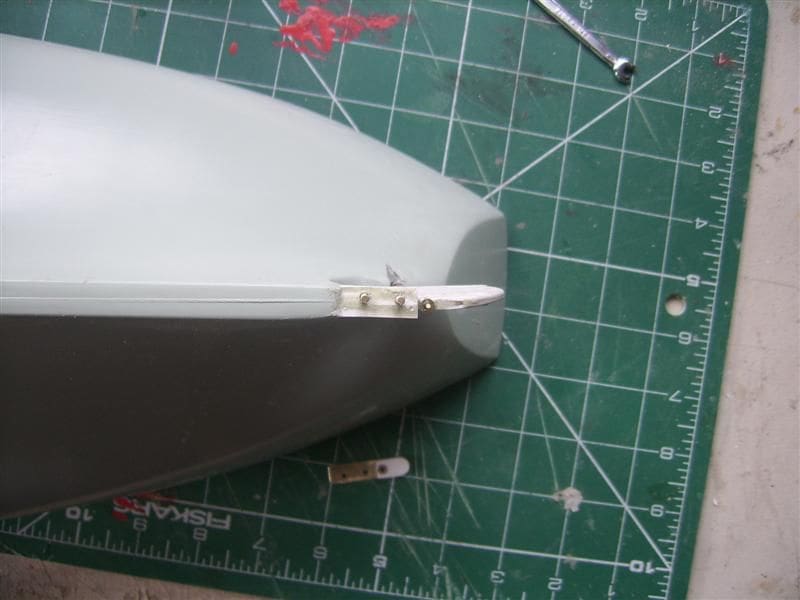
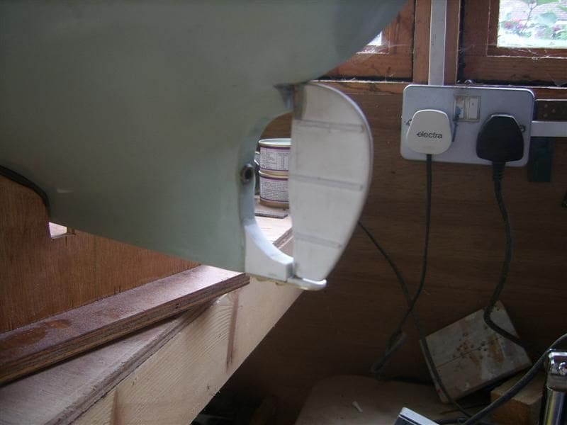
Although the hull is excellent, there was no keel extension where the lower rudder support would be. It wasn’t missing, as the hull lay-up process would not easily allow a lower rudder support to be included in the GRP moulding and it may even be that the rudder would in some configurations not have a lower support. I cut some layers of styrene to shape, glued them together and once set the unit was pegged and glued to the lower stern just under the propshaft position. A smear of Isopon P38 car body filler and a light sanding with wet and dry sandpaper completed the task.
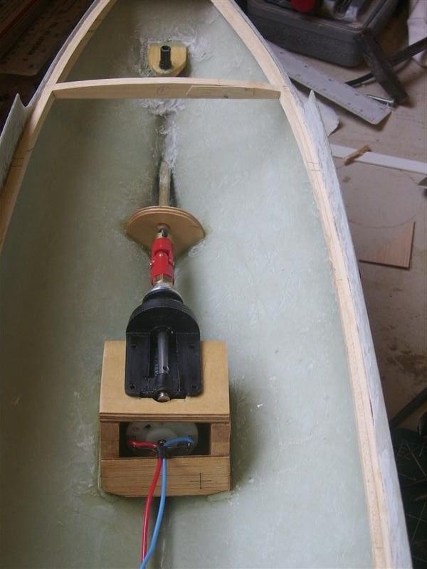
When you have a rudder that is supported at its bottom edge, unless you have an arrangement to remove the blade and shaft, it will be impossible to get it out in order to remove the propeller assembly for propshaft greasing etc. So as with my other models, I fitted a small brass plate at the bottom of the styrene extension, secured to it with two 10BA nuts and bolts. At the same time holes were carefully drilled in the hull for the rudder post and propeller shaft, Photos 2 and 3. The rudder blade itself was also of laminated styrene sheet sandwiching the rudder shaft. All very straightforward, the styrene allowing detail strapping from thin strips of the same material to easily be added to the blade.
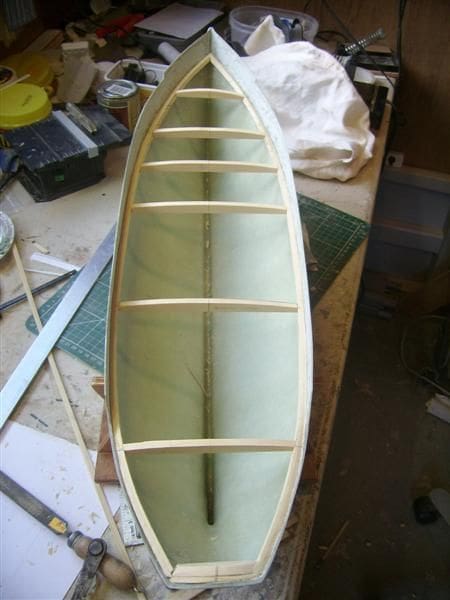
The next task was to glue the wooden deck supports around the inside if the hull. All I will say on this is that I always use laminated 2mm x 5mm stripwood which allows the hull contour to be easily followed, Photo 4. Using thicker section wood usually means scoring or cutting it halfway through to get it to take the curvature of the hull. At this point I chose to construct the fairleads. Why now? Well I felt like it and that is the beauty of scratch building in that within reason you can do the various tasks in whatever order you feel like.
Fairleads
These were made by simply using two different sizes of Plastruct tubing. The smaller diameter was heated with a hair dryer in order to achieve an oval profile which pushed through the prepared oval fairlead holes in the bulwarks. The larger tube was again heated to an oval profile from which small pieces 3mm approx. were cut. These pieces were then glued either side to the inner smaller oval tube in the bulwarks and then sanded down to size.
Deck
Once the main deck edge stringer has properly set, some shaped cross beams were glued across the hull ensuring they did not obstruct where I intended there to be the access openings to the hull interior, Photo 5.
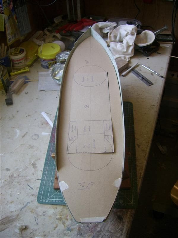
My method was to accurately cut a close fitting sub-deck template from thin card, then cut a ply deck to match and then mark on this using another template the positions of the various deck structures and access openings. Obviously, one has to multi-task somewhat, as ideally the hull deck supports that go across the hull should not be within the proposed openings, so some forward thinking and planning is necessary. Card templates do however save wasting wood. Photo 6 shows the ply deck with part of the access openings template laid over it.
The 545 motor coupled to a 2:1 reduction unit was installed prior to the deck being glued in place, Photo 7. As Glynn Guest has noted with his Free Plan articles, installing the drive train is so much easier when you have easy access rather than after when the deck is fitted.
Access for the motor was to be under the removable wheelhouse and access to the r/c equipment and drive battery would be under a hatch situated between the wheelhouse and the forward gun platform. Photo 8 has the sub-deck in place, with access hatch coamings fitted and indeed it is also now partly planked.
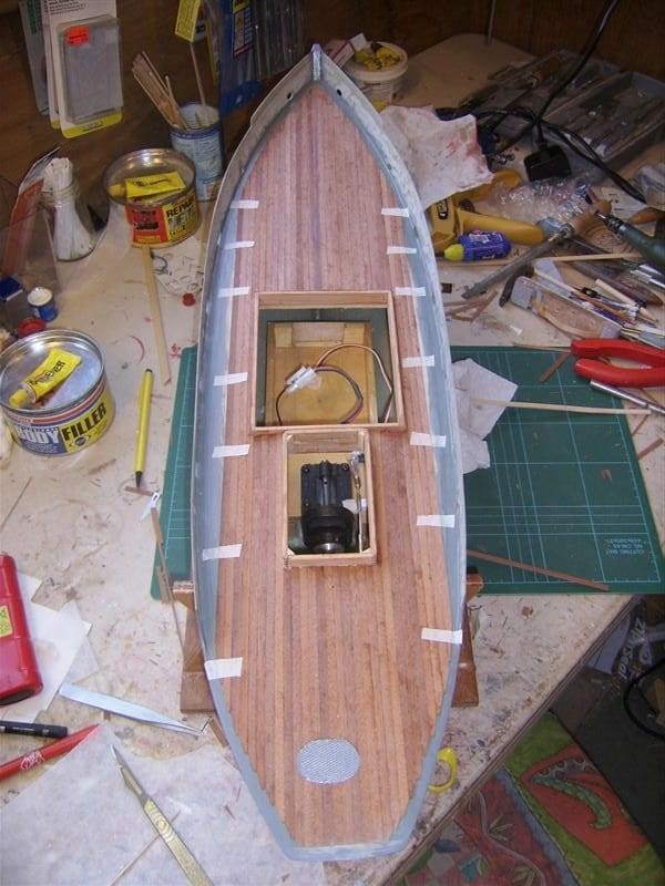
One access problem did present itself and that was how it would be possible to get to the rudder horn. This I overcame by inventing a maintenance hatch which was sufficiently large to allow access to the rudder horn assembly. This can also be seen in that last picture just in front of the stern.
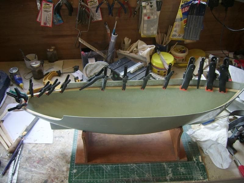
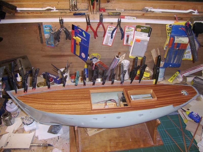
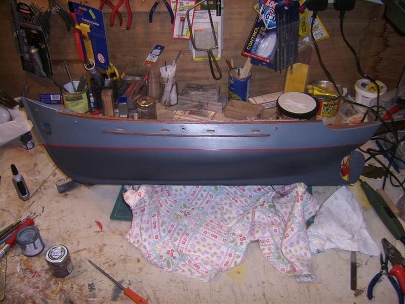
Photo 9 shows the planking to the inner face of the bulwarks well underway. The bulwark supports were made from Plastruct T sections with the centre strip simply tapered from bottom to top. With the hull basically completed, all that remained was for it to be painted and the deck given several coats of varnish thinned 1:4, Photo 10. Several coats of thinned varnish produce a much more resilient and hard wearing finish than one or two heavy coats that don’t really soak into the wood.
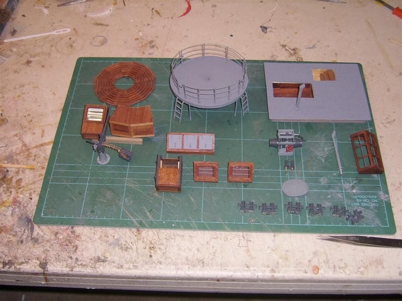
Foredeck parts
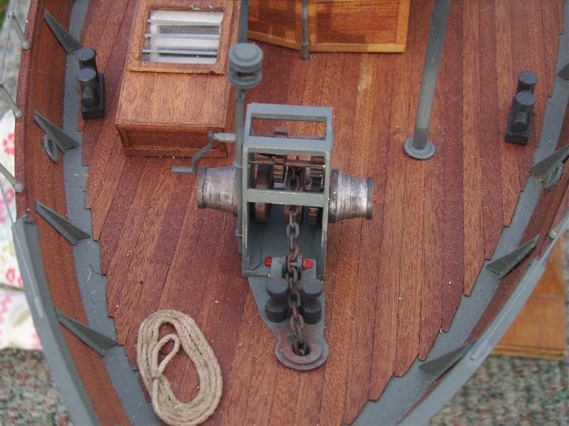
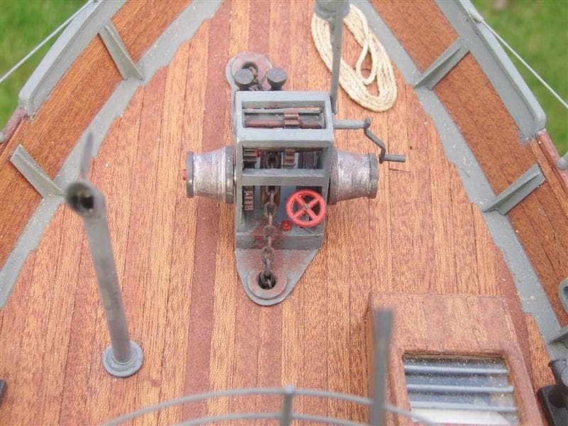
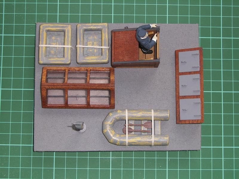
From now on it was all downhill in that the detail part of construction was fairly straightforward. All of the finished foredeck component parts are shown in Photo 11 and the forward winch is highlighted in Photos 12 and 13. The gears for this were obtained from Hobby’s, website: www.hobby.uk.com. As I have a small lathe, the tapered winding drums were turned up from brass rod as were the anchor chain guides. Anyway, now I shall explain in detail how the more complicated items were constructed.
Gun platform
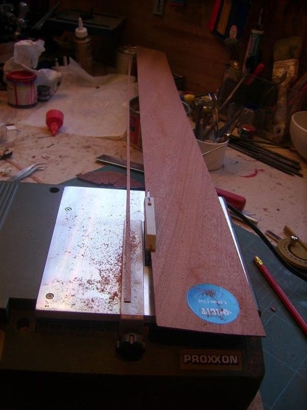
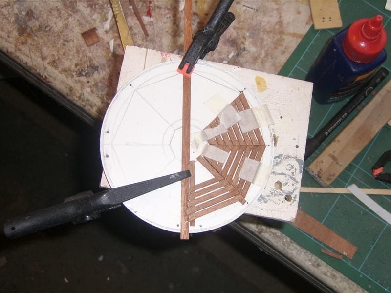
The actual construction of this was straightforward once it had been broken down into smaller units. The only tricky part was drilling the 1/16 inch brass tube stanchions. I have a small Proxxon pillar drill stand and compound table (not that expensive, but excellent). Once set up and with a little patience it was fairly easy to drill 0.8mm holes top and centre. I used the first stanchion to line up the rest. A small brass nail inserted in the first hole drilled in each stanchion ensured the second was drilled in the right place. Each stanchion was then trimmed to size. Potentially the most difficult part was to make accurately the circular duck boarding. I chose to cut my own strips of 1/16 inch mahogany using a Proxxon table saw, Photo 14. Proxxon tools are of excellent quality and money is well spent on them.
Using a cardboard template the twelve segments were drawn. The template was covered with baking paper to provide a non-stick surface which then made it reasonably easy to construct each individual segment, just patience being required, Photo 15.
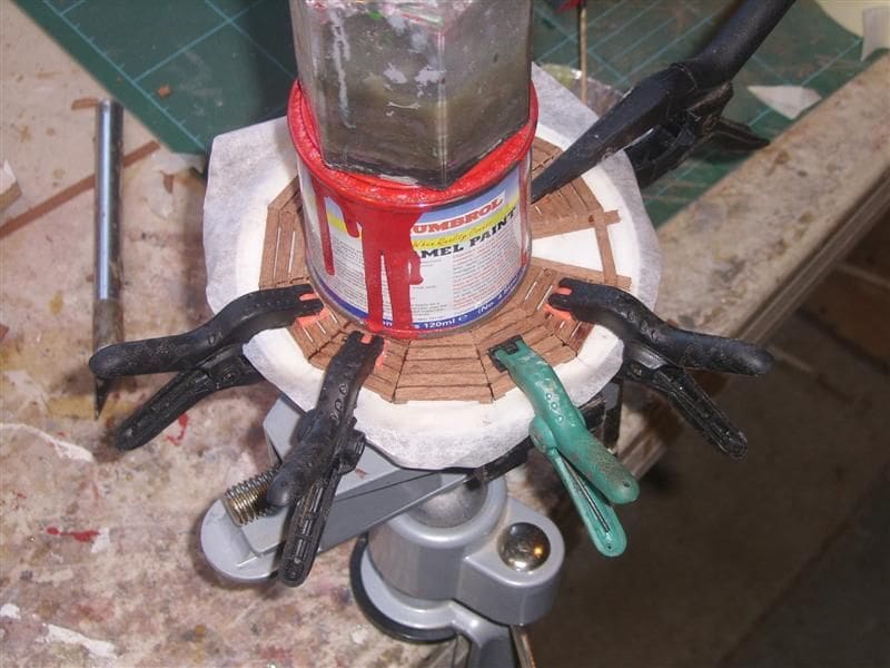
Once all of the segments had been made they were then glued together and held flat to avoid warping, Photo 16.
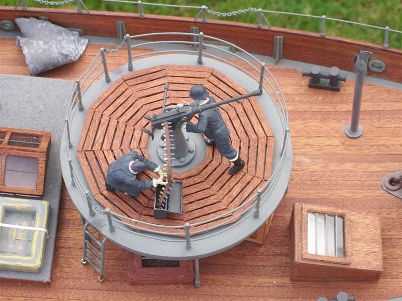
The gun platform, excluding the duck boarding, was then assembled using 1/32 inch brass wire for the handrails and sprayed. The wooden duck boarding received the same varnish treatment as the main deck and was then glued into place. Photo 17 shows the finished item with the front of the main hatch just to the left. Photo 18 shows some of the other deck details.
Main hatch
I wanted to produce the impression of a civilian trawler that had been commandeered and altered to its new military role. To my mind this meant the main hatch on the original would have been covered with tarpaulin beneath which would have been the crew’s quarters. To obtain the tarpaulin effect I covered the hatch with some spare sail cloth material and sprayed it several times with the spray gun held at double the normal distance away from it. This covered the cloth with a mist that did not clog the porous surface of the cloth and successfully achieved the result desired.
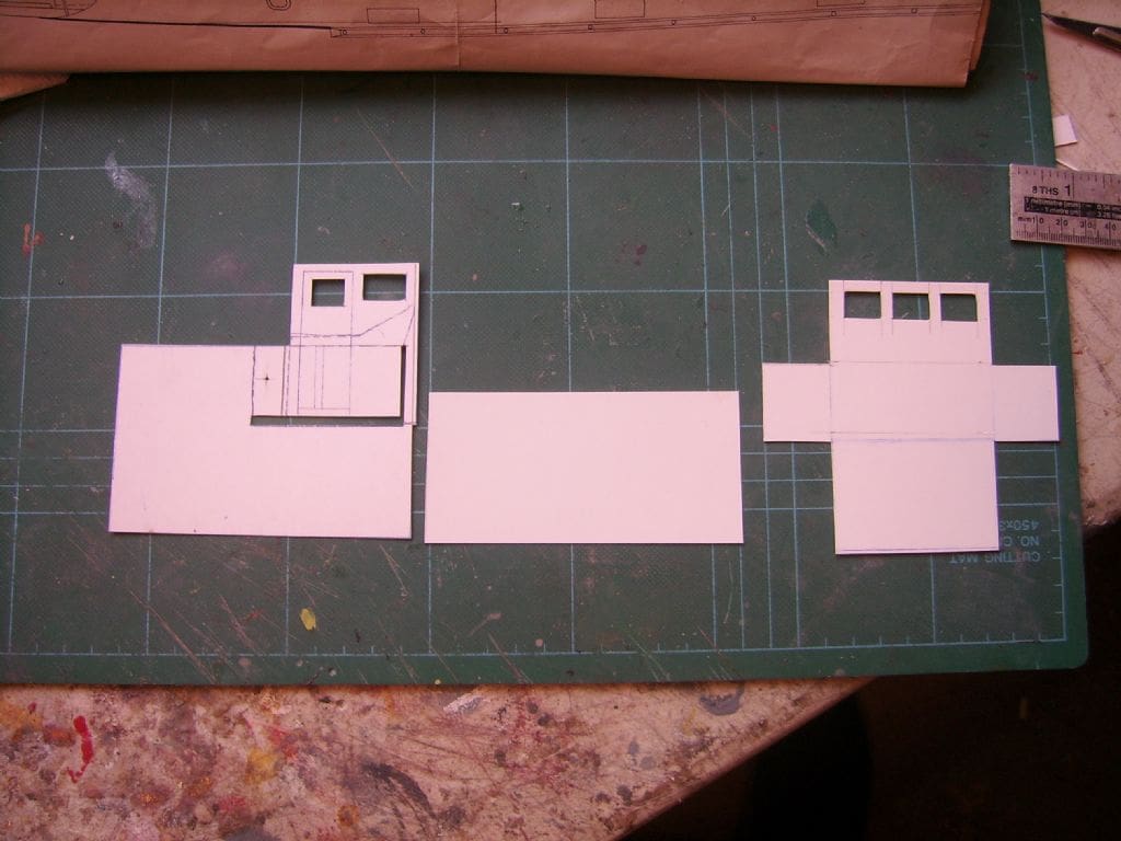
Wheelhouse
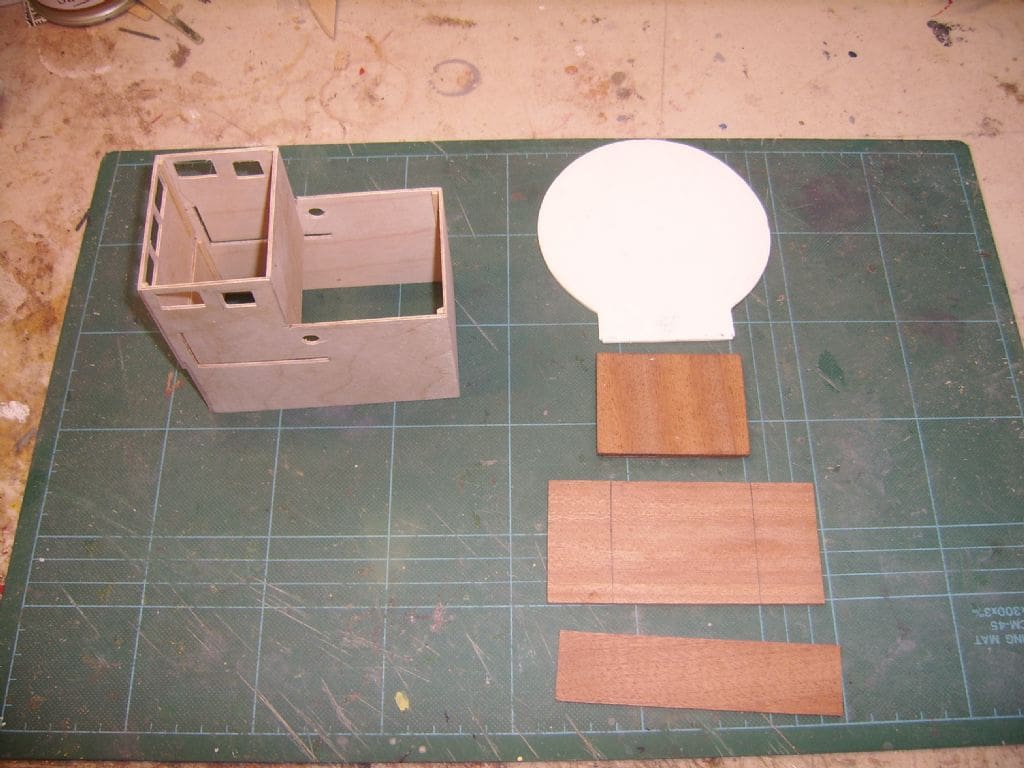
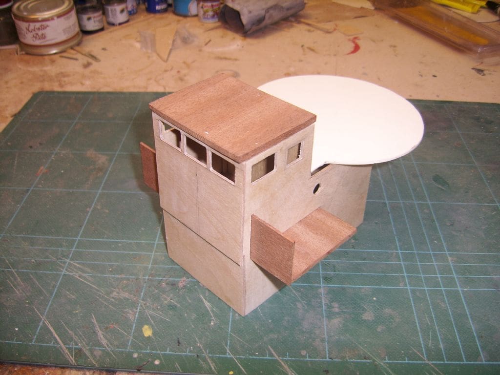
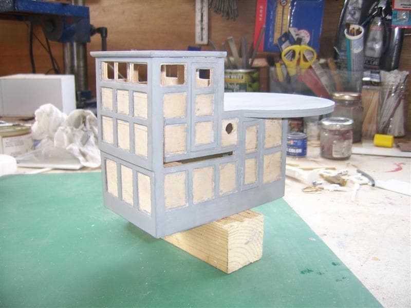
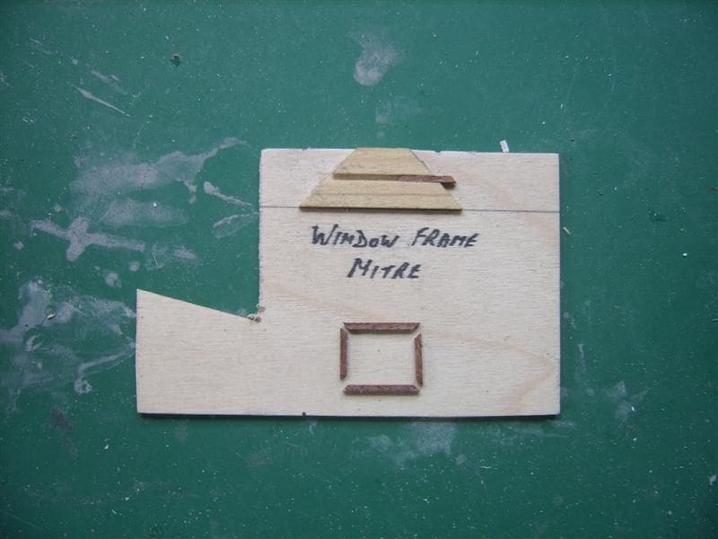
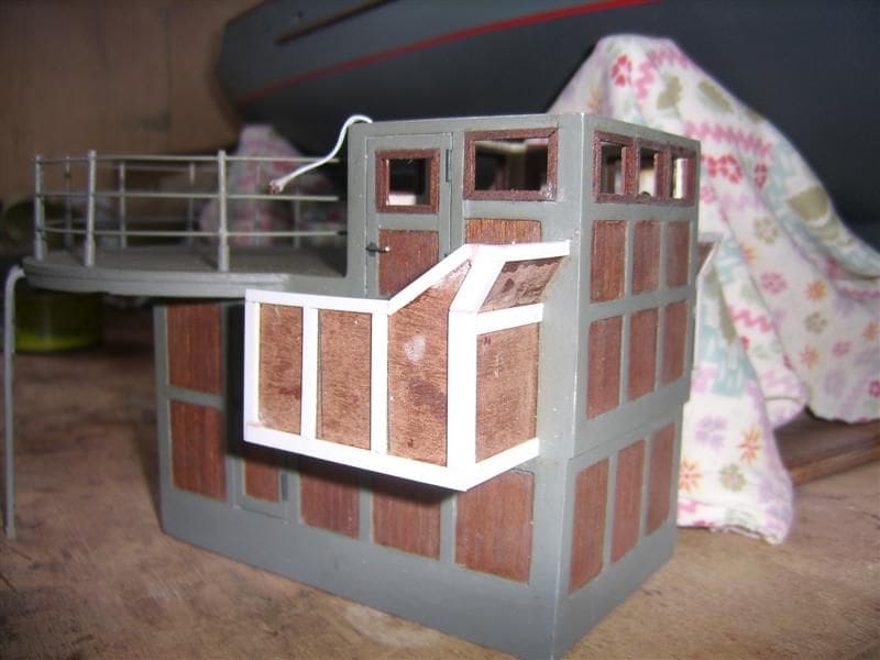
This is a complete model in itself and did require some careful forward planning. First I cut templates from cardboard and transposed these to 1/16 inch plywood. These are shown in Photo 19 and the part assembled wood parts are in Photo 20. The wheelhouse wings were then also dry assembled into place, Photo 21. Plastruct styrene strip was used to simulate the metal framework and painted as in Photo 22 and then the spaces between them were filled in with 3mm x 1mm mahogany strips. It is also important to mitre the window frames properly and a little jig makes life so much easier. Photo 23 is of what I ‘knocked up’ to facilitate that task.
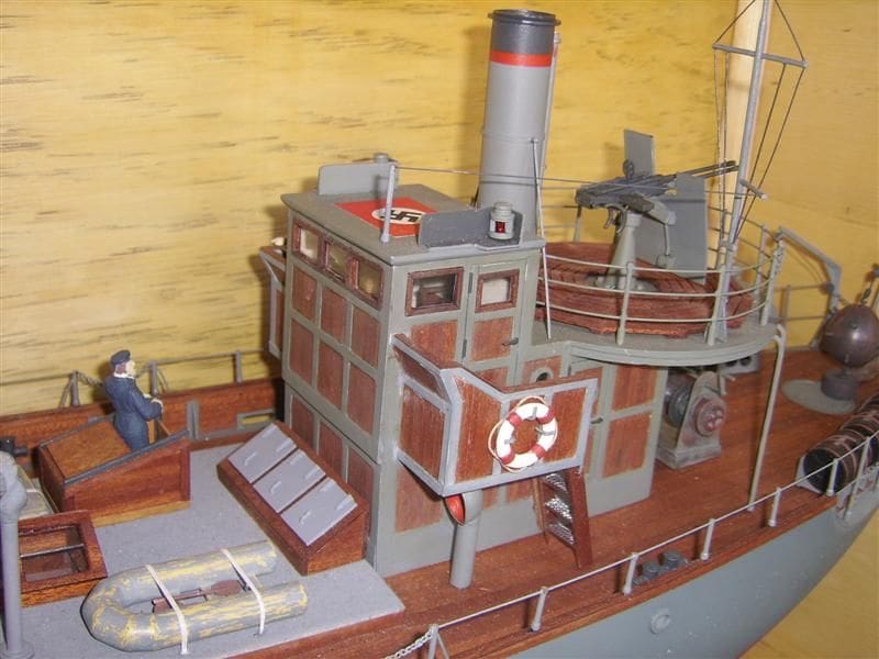
Photo 24 is of further progress on adding the simulated metal framework and Photo 25 is of the finished wheelhouse. Yes, maybe there is some ‘modeller’s licence’, but I like it as it is and it certainly doesn’t look out of place.
Depth charges
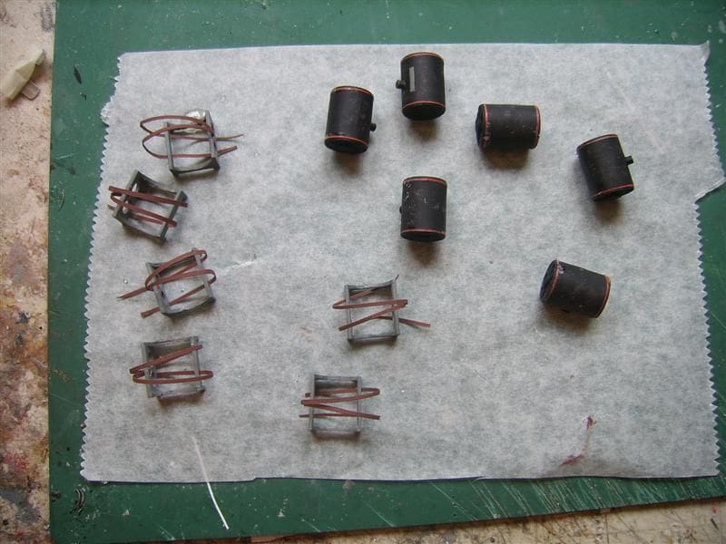
After a bit of hunting around I found some plastic tubing of the right diameter which made the construction of the six depth charges fairly straightforward. Photo 26 shows the depth charges with their saddles and harnesses ready for final assembly. (Fax roll inners can be a useful source of plastic tubing – Editor)
Mines
The primary role of a Vorpostenboot was anti-submarine warfare and mine laying. Although not shown on the plan I decided to also depict some mine laying activity with a mine stowed on the stern. I used a one inch wooden ball to which I added some P38 to one end to elongate it. After some sanding and adding little more P38 a profile close to that of a mine was achieved. Short pieces of 3/32 inch brass tube spaced at 120 degrees represent the contacts and Photo 27 is of it in a naked unpainted form with Photo 28 being the finished result.
Navigation lights and smoke effect
During construction, the wiring for the navigation lights was installed and provides both the port and starboard lights as well as the double white pod mounted bow lights and single white stern light mounted on the aft gun platform. The small 6v Seuthe smoke unit was easily fixed inside the funnel.
In Photo 29 you will see a simple switching unit which consists of a mini servo with one of the round control discs shaped into a cam operating two micro switches. Using a Hitec three channel radio outfit the third channel has three positions marked – All off/lights on/smoke on. Because you would not necessarily want lights and smoke on together you will see two small isolation switches for lights and smoke. This allows for a combination of settings and also provides a manual ‘OFF’ when the model is put away between sailing sessions.
Flags
To complete the model the Kriegsmarine Ensign (D51 and Hakenkruz (VD51) were obtained from BECC Flags and Photo 30 is of the model when finished in the Autumn of 2008.
Conclusion
Surprise, surprise! The model sails brilliantly, responding crisply to the helm and holding its line excellently when going astern which is unusual for a single screw model. My impression is that it will make an excellent regatta steering model boat, is of a convenient size and because of its trawler origins is able to carry quite a large drive battery and incorporate special effects. I included a simple smoke unit and lights, but the choice is yours. I have not included a ‘blow by blow’ account of how to wire up the motor, install the radio equipment, paint the boot topping etc., because there are others in this magazine who do it from time to time and far better than myself, but I hope that my little article will inspire others to have a go at this or something similar. The internet is a great source of information and even if you do not have the internet at home, most public libraries can provide basic training and access to the world wide web.
The Kingston Mouldings hull is of very high quality and cannot be faulted as is their service. Some of the fittings are available from Waverley Models as already mentioned, website: www.waverleymodels.co.uk.