Sea-Jet Evolution
TERRY SMALL reviews the Robbe kit
Enjoy more Model Boats Magazine reading.
Click here to subscribe & save.
After many successful sales years for the Robbe Sea-Jet fun boat, the time was ripe for a successor and this is the Sea-Jet Evolution. This new design has been both visually and technically overhauled by learning from competition racing craft, so its appearance is significantly racier than its predecessor, plus it has an improved roll stability. Thus, the hull has been made wider and lower and to give the Evolution the power it deserves, Robbe have equipped it with two electric brushless motors. The two propeller shafts are coupled directly to the motors, therefore there are no gearboxes or flexible couplings to absorb any of the power. A centrally mounted rudder and the new hull shape guarantee high speed and manoeuvrability. Length is 685mm, beam 240mm, height 370mm and total displacement 2100gm.
The kit
Robbe are never short on quality or quantity and have produced a very comprehensive kit, Photo 1. This includes two good quality brushless motors, a two piece hull and seat section in black ABS vac-formings, all requiring no painting, which is fine as long as you like black! The driver is a vac-forming that does need painting after assembly. An ABS boat stand, CNC cut plastic sheet parts and running hardware etc. are included, so all that needs to be purchased are batteries and a basic two channel radio set with one servo and two brushless motor speed controllers. These last items can be a significant cost, ranging from low to high prices. Instructions including exploded diagrams are all in the usual Robbe format with section numbering representing general assembly sequence and cross referenced to the part number. A separate sheet gives a clear understanding of the profiled parts including an electrical wiring diagram.
Construction
Next up is the seat with its supporting frame. A bit of trimming may be needed to achieve a good close fit, at the same time ensuring the retaining bolt is in the correct position. I always just lightly ‘tack’ such framework parts in position with superglue before applying epoxy glue in any quantity. It is thus an easy matter to break the joint at this stage rather than later when loads of glue has been applied. Photo 7 is an underside view of the seat with its internal framework.
Radio control
NiMh batteries respond well to a regular charging and discharge cycle and if you can afford it, I would recommend the purchase of a good slow and fast charger that can be used for a number of different types of cell and work both from the mains or a 12 volt battery source. I currently use a Graupner Ultramat 10, Part No. 6410.
Hull and deck joint
Next up was to fit the U shaped rubber fender which fits over the joining lip. For this, superglue gel (slow set) was squeezed into the bottom of the U shaped rubber (in sections) and then it was pushed into the required position, slightly stretched and held with bulldog clips awaiting the glue to set, Photo 12. This whole task takes no more than 30 minutes or so as you work around the hull.
Driver
For painting, he had an all over white primer coat from the Halfords range of car spray aerosols, then the colour coat was from the Revell/Humbrol enamel tinlet range, Photo 15. The driver is held in position on the seat using a suitable self-tapping screw in his posterior. Velcro is supplied, but the screw is more permanent – he may not float if he falls off in the middle of the lake! The seat is supplied black, but I sprayed it in grey primer. All the painted surfaces were then left for four days before having a single airbrushed coat of Humbrol satin varnish to seal them.
Decals
These are self-adhesive and require cutting out with scissors and/or a sharp knife. The various box lid pictures show where each sticker needs to go. Application is easy by having a small bowl of very mild soapy water handy. Remove the backing paper, dip the decal in the water and place on the model. The idea of the soapy water is that it allows the sticker to be positioned and slid more easily, then by smoothing out the sticker and starting from its centre, this squeezes out the air and water allowing it to adhere permanently, Photo 16. The tricky decals to apply are around the foot treads, Photo 17.
Setting up
It is best to apply a small amount of silicone grease or equivalent on all the shaft and rudder post moving surfaces to lubricate and make them fully watertight. Trimming the model and setting up the radio gear is most important, this second task easily being done whilst the model is on its stand. Ensure the Tx control sticks are at neutral and the trims likewise, turn on transmitter, connect up the drive battery pack and all being well, the electronic speed controllers will start to self-set and once this is complete after just a few seconds, it should be all be ready for operation! An initial check by applying a little throttle and both motors should start, but contra-rotate, with the handed propellers turning in opposite directions. This should be anti-clockwise for the port and clockwise for the starboard when viewing from the stern. If all is okay, the rudder throw can then be checked and if necessary adjusted by altering the length of the linkage in the boat or using the transmitter trim setting.
On the water testing
A calm day was chosen for the first test run as after having a major mishap with another model using brushless motors I was a little worried to say the least. These motors are fast, powerful and very efficient, BUT you do not get instant reverse with the reversing types of brushless esc, and this model has non-reversing controllers anyway! So, thinking ahead of your model’s direction of travel and speed is a very important consideration.
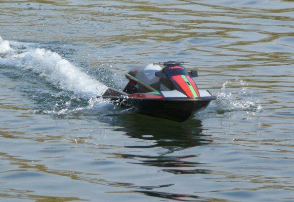
The usual bank side tests took place making sure before the ‘off’ that the hatches were secured and the seat firmly on. No weed in the water or objects that could cause problems were noted, so all was ready to go. The model was placed in the water, it balanced and floated okay and gentle power was applied with the throttle stick. Up came the front and Sea-Jet Evolution was off and with a gentle application of rudder, this indicated a reasonable turning circle. Full power was applied generating more lift in the hull with more loads more speed and yes, it was moving fast! Turning at speed was very responsive and controlled and once throttled back, the speed soon fell away, but this is not instantaneous with a momentary delay measured in fractions of a second. A quick check inside the model at the river bank and there was no water inside and the motors were hardly warm. Running time from the battery pack at high speed was around nine minutes, depending on the charge and state of battery pack. As soon as there is a noticeable drop in speed indicating the battery is starting to ‘dump’, that’s the best time to bring the boat back to the bank. You will notice from the running photos that I have not fitted the figure. The simple reason is that I forgot him on the day – sorry! Please also note that there is a small additional rudder inspection hatch at the stern, fitted for personal convenience and held down with double sided tape.
Conclusion
The Robbe Sea-Jet Evolution is a very easy model to assemble and by following the straightforward instructions, the builder cannot go far wrong. The motors and drive shafts due to the positive slot together framework fit and align perfectly, but do properly key and glue the framework to the hull. Mind you, that does not mean you should pour in loads of glue as it can add unnecessary weight and do grease the drive train periodically. It goes well, it looks great, it’s fun on the water (with or without the figure!) and it goes fast, but remember it’s a model that goes forwards only, and brushless motors can be unforgiving in an emergency ‘stop’ mode, so care is needed on a busy lake. However, it is a shame that the appropriate dedicated esc’s are not included and are extra to the basic kit which was supplied by ‘A Model World’, tel: 01606 891999, website: www.amodelworld.co.uk Current kit price is approx. £184.50.

