The little boat sailed o’er the pond,
Puffin with all its might;
Reg, he was as pleased as Punch,
It was a wondrous sight.
All morning long the boat sailed on,
All thought of time had gone,
But when, at last, the bonny craft
Ran out of steam and puff,
Then Reg was clearly heard to cry
‘Enuff, enuff, enuff’.
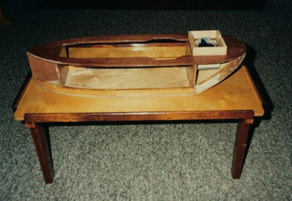
Pic 1: Early tentative stage of construction. A large engine room.
Enjoy more Model Boats Magazine reading in the monthly magazine.
Click here to subscribe & save.
If you have always fancied making a little simple steamer, but for some reason have ‘never got round to it’, then hesitate no longer. Have a go, and if you make the engine as well you will have some real street ‘cred’, as well as much enjoyment and fun at the pond side and, of course, on the pond too.
If you are in luck there may be a metalwork class at the local Evening Institute. If so you are home and dry. Don’t hang back thinking everyone in the class will be making a triple expansion engine, coal-fired of course, or even a Flying Scotsman. They probably aren’t. Some chap may be struggling just to make a toasting fork. The local library should have some books containing designs of simple model steam engines, so have a go. Remember, you are a modeller so any problem can be resolved.
The making of Puffin
Early in 1997, as a special treat, I bought myself a copy of ‘Model Engineer’, just as my father had done in the early 1920’s, and for the same reason – to drool over the photos and descriptions of the wonderful models therein. “Can we have one of those, Dad?” No chance! I’d have to make do with an 0-4-0 clockwork Hornby.
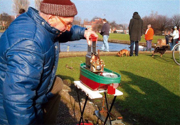
Pic 2: Dropping in the engine, filled, fuelled and oiled. Then it is switch the radio on, set up the superstructure and aerial, swing the prop, set up the superstructure and aerial, and launch.
Along with the ‘Model Engineer’ was a small booklet advertising a Nexus publications booklet called ‘Twin Cylinder, Horizontally Opposed Marine Engine. Lathe not required’. (This is still available from our Customer Services – Plan No. MM531 – call them on 01689 899 228 or email: [email protected]. Ed.) I do have a lathe but it’s a homemade woodturning job. ‘Right, that’s for me,’ I thought, ‘I’ll have a go.’ So, just for fun, I sent for the small twelve-page booklet of sketches and instructions on how to succeed at making a little twin-cylinder steam engine. Putting it into a boat had not yet occurred to me.
The engine was beginning to take shape, albeit slowly, when, in W.H. Smith, I noticed a copy of April 1997 Model Boats. – the April 1997 edition. On the cover was the offer of free plans and instructions for building a small steamboat to conform to the requirements of the Ministeam Class. These were the work of Glynn Guest, based on Beadle, a boat that he himself had designed and constructed. I bought the magazine and was hooked. I would put my little twin-cylinder engine into a boat and sail it across the local model boat pond, which I hadn’t visited for at least 50 years. (Unfortunately there are no copies of this plan in our files, however photocopies of the article are available and whilst this does not include any dimensions there are a number of step-by-step photographs which will be very helpful. Ed.)
Apart from building a doll’s house many years earlier this was to be my first attempt at modelling. A joiner by trade I baulked at Glynn’s advice to construct the boat using balsa. It is, of course, the ideal material if you know how to use it, but I don’t. It reminds me of much of the present-day timber, often referred to as ‘rhubarb wood’ or ‘banana wood’.
I had some quarter inch ply in the shed and decided to use this for the bottom of the hull, the bulkheads and the deck. For the sides of the hull I bought a six foot by one foot piece of 1/8in ply with the grain running lengthwise. The laminations to reinforce the joint between the bottom and sides of the hull were cut from 5/16in softwood.
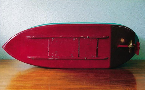
Pic 3: Underneath Puffin with ballast (lead flashing) pinned beneath the two skids out of the way and not cluttering the engine room.
Photo 1: After following Glynn’s clear instructions the hull was ready to take the sides, but I began to wonder whether my decision to use the longitudinal grain 1/8in ply had been the right one. Two weeks beforehand I had cut the ply to very close to its finished shape, then pulled the two ends together to form a U-shape, using strong string to hold them in position. This was reasonably easy because the width of the ply at the centre line of the stern was less than two inches. Throughout those two weeks the ply was ‘in purgatory’. I gave the stern portion regular doses of water, and left a wet cloth in the bottom of the ‘U’.
It was easy enough to fit the ply round the stern with the grain horizontal, but getting a good fit at the bow was a real problem. I had to use two pieces on each side, with the grain vertical at the bow. To hold the ply up to the hull I used the string and block method; placing the ply as near as possible to its final position, holding it in place with string tied as tightly as possible, then inserting small wooden blocks between string and ply, thus getting the whole job really tight. Any alterations or adjustments could be done simply by removing a few blocks to allow some play.
Having decided that it would be feasible to use 1/8in ply for the hull sides it was time to turn my attention to fitting the propeller tube so that it was in line with the engine. Working from Glynn’s instructions for Beadle, the tube was lined up but not yet glued in its final position.
Photo 2: In Beadle, the single cylinder oscillator is screwed to the bottom of the hull and connected to the prop shaft in a more or less permanent position. The boiler is connected to the engine by a fairly long flexible steam pipe, enabling it to be lifted clear of its mounting for filling the boiler and for refuelling the burner. I had no idea what sort of flexible pipe was required so I made the engine and boiler as a single unit, using copper pipe, so that it could be lifted in or out of the hull using a pair of spring-loaded tongs. Owing to the horizontal layout of the engine a gap of five and a half inches was required in the deck for clearance. This was to cause a bit of a problem, but one that could be overcome.
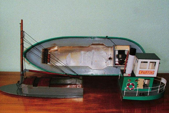
Pic 4: The cut-outs in the deck to take the twin cylinder engine are clearly shown, as is also the thin gauge alloy lining the hull bottom, sides and bulkhead. Under the deck is lined to. The servo, batteries, etc., are in the box above the prop shaft. Some detail may be seen of the fore and aft superstructure in alloy, with the engine room and wheelhouse in 1/8in ply.
The engine unit is located on simple pegs in the hull bottom, and cannot move unless lifted forwards and upwards with the tongs. The connection with the prop shaft is simply made: two spigots on the flywheel engage with a T-piece on the inboard end of the shaft. Simple and crude, but it works.
Photo 3: In the engine room, thin alloy sheet lines the bottom, sides and bulkheads, and the underside of the deck, and does its job well. The electrics – servo, receiver and batteries – fit into a removable alloy box let into the deck above the prop shaft and, to avoid cluttering the engine room, the lead ballast (flashing) goes neatly between the two skids which are pinned and glued under the hull.
Photo 4: Owing to the wide cut out in the deck to take the engine, there appeared to be no easy way to fit a combing round the opening to keep out any water that might be shipped. The only solution I could come up with was to cover the whole area around the opening with alloy sheeting, using a bit of 1/8in ply for the wheelhouse. Breakfast cereal carton was used to make a template so that any snags could be spotted before attempting to knock the alloy into shape. The area in the bows was reinforced with a piece of thicker alloy, as it was to take the mast and tabernacle, etc. This was fixed in place using Araldite.
Photo 5: Painted and nearing completion the boat was given flotation trials in the bath to give me an idea of the amount of ballast required. Then came the day, in late October, when, with great trepidation, I prepared to venture to the pond. There seemed to be so many things to attend to and to remember to take – mainly things with which I was unfamiliar: the radio equipment, a flask of boiling water, a filler (I use a small treacle tin) to gauge the right amount of water for the boiler, fuel tablets (Hexamine) and a small amount of methylated spirits to start them off, and a lighter. In addition, there were spanners, a screwdriver, lifting tongs, some oil, the stand for the boat to rest on whilst being prepared for launching and, of course, the boat itself. I was sure I would find I ‘d left something important and essential behind.
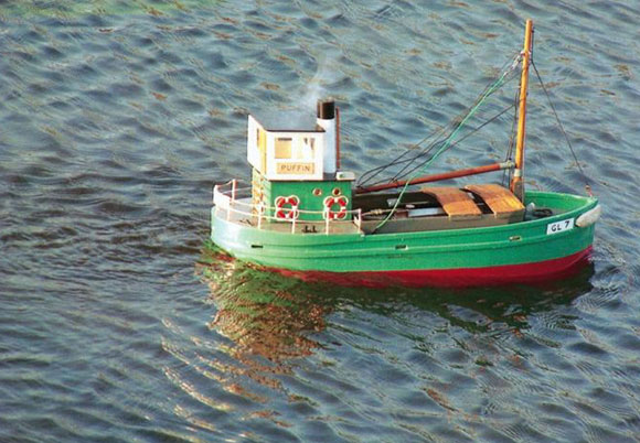
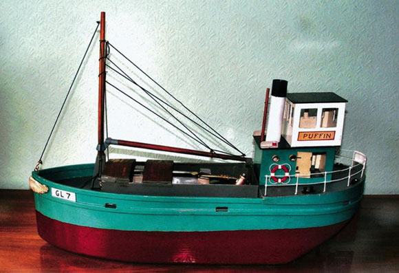
Pic 5: Puffin under way.
I needn’t have worried. With the boiler filled, the fuel burning steadily, and much help and speculation from the spectators, the engine was popped into the boat and the hatch cover placed in position. Then, to cheers from those around, the little boat was launched. It steadily made its way to the middle of the pond – and stopped! An ignominious maiden voyage. I’m sure it wasn’t the first maiden voyage to end thus. A rescue tug was soon standing by to push the cripple back to the pond side.
When the engine was lifted out it was obvious that the fire was out. It was quite windy and the general opinion was that a gust had blown the fire out. To keep the spectators happy two engine-room vents were removed and the holes taped over before a second attempt was made to cross the pond. However, the result was the same – engine failure. It was ‘back to the drawing board’.
The engine had run well on the workbench and I was not convinced that the fire was being blown out. In fact I thought the problem was more likely to be inadequate ventilation. Putting a few more portholes and an engine-room hatch in the superstructure cured the burner problem immediately, proving that my theory had been correct.
Outings to the pond were somewhat curtailed during the winter months, but came the Spring and some sunny weather the boat was performing well and would run for twenty-five minutes per filling of water and fuel. I was gaining in experience and confidence and, what’s more, was enjoying every minute at the pond.
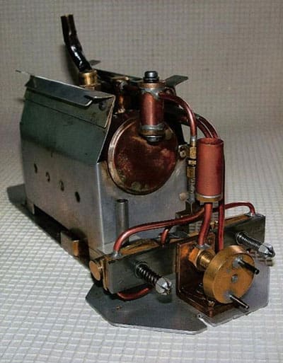
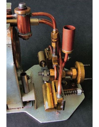
Pic 6 & 7: The twin cylinder engine used in Jenny. Note the displacement lubricator in steam line, and drip lubricator to main bearing, a 3/8in brass bolt. The strange device below the boiler holds the drip-pan in place below the cylinders.
Developments
One day, someone at the pond said that the boat reminded him of a Clyde Puffer. Some imagination! I had become a regular subscriber to Model Boats and had noticed the occasional articles about puffers, with photographs, and rather liked the look of them. They seemed to be good, honest little boats – nothing fancy or glamorous. Using a Beadle hull, could I make a boat resembling a Clyde Puffer? I was determined to try.
In case my attempt at making a Puffer turned out to be a disaster I thought it best to leave the twin-cylinder engine in its present form, with the exhaust steam going up the funnel amidships, and make a single-cylinder oscillator, which would exhaust practically vertically into the Puffer funnel which is well astern.
Very little equipment is required to make a simple oscillator, but a lathe would certainly make the job easier. After talking to fellow-enthusiasts at the pond it appears that the stumbling block for most people is finding someone able to silver solder (a skill needed in order to fix the boiler ends in place and for the safety valve (filler) and steam take off). This problem was kindly taken off my hands by Mr. Tony Green of Thorpe on the Hill who advertises regularly in Model Boats. Of course, to save you a lot of time and, perhaps, a lot of hassle, Mr. Green would no doubt be pleased to fix you up with a ready-made boiler and one or two of his single-cylinder oscillators, and at a very reasonable price, too. Two of these engines running in line will give plenty of power.
Photo 4: The Clyde Puffer shows fairly clearly how the decking and hatch cover were made so as to bridge the wide opening mentioned previously. For the decking, thin alloy sheet was used, with a portion of a heavier gauge sheet at the bows. For the hatch covers thin alloy was covered with wood and then creosoted. I also used sheet alloy for the stern portion, knocked up round a former, the engine room and bridge being made from 1/8in ply. The funnel is plastic conduit, which runs right through to the deck and helps to hold the whole structure in place. I found making this stern part a bit of a headache, and am sure that any experienced modeller could find a much better and easier way of doing it. The photograph also shows the radio pack in its alloy box above the propeller tube.
An important point I must mention is finding the right propeller for a small steamer. The local model shop did not seem to be very interested in steamboats and suggested that a three-bladed, fine pitch, 50mm diameter plastic job would be suitable and, to a certain extent, it was. With the ventilation problem overcome the boat would chuff steadily around the pond. What more could I want or expect? Someone then gave me four-bladed 40mm diameter brass prop, but there was little to choose between the two.
Pic 8: The rigging is a mess – says Reg! It has been improved since the photograph was taken. The derrick to mast joint is a 3/8in wing nut minus one wing!
One fine, sunny morning a wise old gentleman was watching the preparations at the pond and ventured his opinion. “Son,” he said, “you’re flogging your engine. You’ll shake it to pieces. Get yourself a bigger propeller. You’ll slow the engine, build up pressure and save steam – and money too.” And so I did just that. Whilst on holiday in Bowness I was lucky enough to obtain, from a small model shop, a four-bladed brass 55mm propeller, and this really did improve performance. Not that a Clyde Puffer should scream around the pond, but it did give it a certain amount of purpose and authority.
Whilst working on the stern portion of the Puffer I began to wonder if there was going to be too much top hamper. I needn’t have worried. Although Puffin does heel a bit on sharp turns she is quite steady, and handles very well. The all-up weight, without water and fuel, is just under ten pounds – about twice the weight of Glynn’s Beadle. Perhaps I should have used balsa!
I hope this article has encouraged you to try a bit of authentic modelling. The boat itself is by no means difficult to construct, and if you can also make the engine and boiler then it is 100% yours, excluding the electrics, of course. Have a go. Amaze your friends.
Puffin – a few facts
O/a length 23ins.
Beam 7 1/4in.
Gross tonnage 10lbs.
Engine: 3/8in bore.
Boiler: 6 x 2ins diameter, tested to 70lbs/square inch.
Fuel: Meths (a small amount) Hexamine tablets.
Material for the engine mainly obtained from Macc Model Engineers’ Supplies (for unions, safety valves, etc.) of 45A Saville Street, Macclesfield, Cheshire, SK11 7LF. Tel: 01625 433938.
Not forgetting Tony Green, 19 Station Road, Thorpe on the Hill, Lincoln LN6 9BS. Tel: 01522 681989.