Glynn Guest provides a definitive guide to installing motors and running gear.
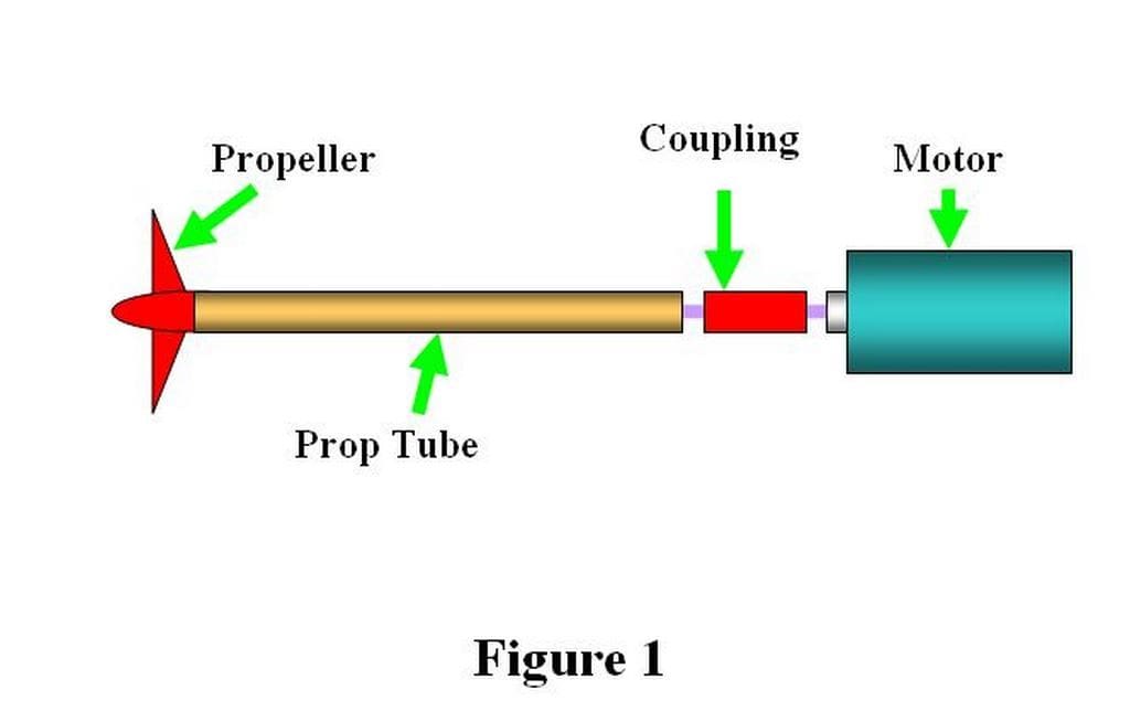
The Drive Line of a model boat is centred on the propeller shaft and the tube it rotates within. At one end the shaft is connected to the motor, at the other is the propeller which turns the motor’s efforts into a propulsive force, Figure 1. Failure to correctly install all of the parts that make up the drive line will result in disappointing performance and unreliable operation no matter how well the rest of the model is built.
When building from a plan or kit, this important stage in a model’s construction should be fully explained. The only exception might be a model intended for experienced modellers and clearly described as such. Alas, far too many examples of vague, glib or even nonexistent driveline installation instructions can be found. I’ve even come across some which if followed would have had the propeller blades fouling the hull should you have done anything as foolish as trying to switch on the motor!
Enjoy more Model Boats Magazine reading in the monthly magazine.
Click here to subscribe & save.
Propeller Shaft and Tube
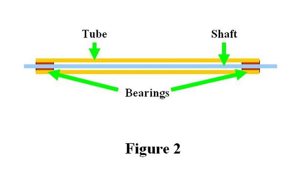
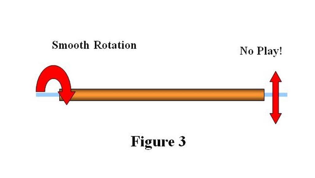
These are usually supplied as a complete set, with a length quoted which describes the length of the tube. A brass tube with a steel shaft that rotates within it is the usual combination of materials. The shaft is supported by two short bearings fitted to each end of the tube, Figure 2. The shaft should slide smoothly through these bearings and rotate freely but with no noticeable ‘play’ or sideways movement of the shaft within the bearings, Figure 3. If the shaft is reluctant to pass through the bearings and/or rotate easily then you might want to replace it rather than hope that it will ‘free up’ with use later on. If excessive play is found between the shaft and bearings then you really have to replace it as it will cause no end of subsequent problems.
The more curious amongst you might ask why not use a simple close fitting tube to support the whole length of the shaft and so save the need for two bearings. There are two answers to this question. Firstly, it is rare to find a propeller shaft that is exactly straight. Forcing even a slightly bent shaft into a close fitting tube will result in lots of friction when the motor tries to turn the propeller. This will in turn lead to poor performance (speed and duration) and possibly an overheated motor which may reveal its unhappiness by attempting to ignite inside the model. Before anyone suggests using a tube with a slightly larger internal diameter, it must be pointed out that this will just provide a path up which water will readily flow, never a good idea in any marine craft.
The second reason is to do with lubrication. If the space between the shaft and tube is filled with lubricant it will reduce the friction with the bearing surfaces as the shaft rotates. It can also act as a barrier to any water that tries to seep past the lower tube bearing. If a straight shaft were running in a close fitting tube some lubricant would still be required between the rotating shaft and inner tube surface. The gap between these two would be very small (close fitting remember) and lubricant would create a large ‘viscous drag’ as the surfaces move past each other. This effect can be surprisingly large as I found with a small steam powered model in which this ‘viscous drag’ in a close fitting tube was high enough to stall the engine. With the tube firmly embedded in the model, the only solution was to reduce the diameter of the middle part of the shaft to create a bigger gap between shaft and tube wall. Thankfully this worked but it would have been an unnecessary chore had the kit manufacturer done their job properly.
Of course someone is going to now suggest using a plastic tube which will have less friction. But it will also be more flexible. Lack of stiffness in any rotating system can lead to vibration, excessive wear and quite often loud unwelcome noises. Suitable plastics can however be used to make the bearings for metal tubes provided they produce smooth operation without any ‘play’.
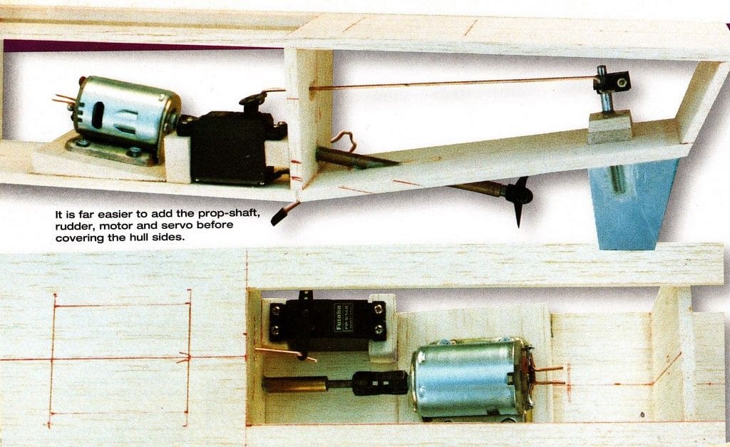
Installing the Drive Line
It is usual to install the propulsion items into the hull as soon as possible during construction. It is much easier to work with good clear access than have to fiddle through narrow deck openings. If a kit/plan instructions suggest otherwise then think about it carefully as they may be a good reason for doing things the harder way. Of course the designer/manufacturer might just be a sadist.
The propeller tube should be the first thing to fit into the model. The instructions and plans ought to clearly show where the propeller tube passes through the hull. Kits which include readymade hulls may already have the location for this hole marked. It is wise not to be too trusting and double check that any such markings are correct and that the whole drive line can function correctly with the tube in this position.
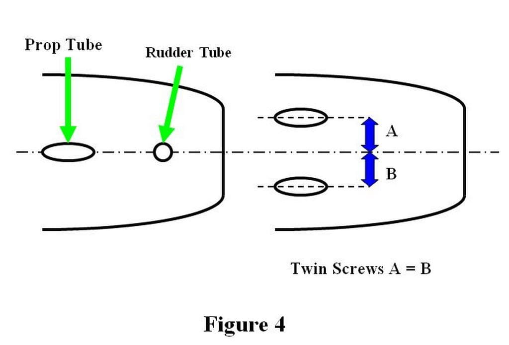
If no markings are given then you have to locate the correct position. The first thing to do is mark a centre-line on the hull. The holes for a single screw and rudder vessel should be along this line, or if twin screws are fitted, then equally spaced from this line unless otherwise stated in the instructions, Figure 4. If you fail to do this then the model will still operate but you run the risk of encountering some odd sailing characteristics.
When making holes through plastic hulls it is wise to cover the area around the hole with masking tape to prevent any accidental damage to the surface while drilling/cutting. The rudder tube hole can usually be drilled to the exact size but it is always a good idea to start with a smaller pilot hole first. The propeller tube, usually being at an angle to the hull bottom, will need an elliptical hole. The obvious way to make this is to drill a hole to match the tube in the middle of the desired opening then use a round file to get the desired shape, Figure 5. The aim should be for a snug fit without any suggestion of the hull being deformed when the tube is at the correct angle.
An alternative to the elliptical hole could be a suitable slot cut into the hull bottom. This can be easier to fit the propeller tube through hulls that have thick wooden sections. In this case, some packing before and after the tube will be needed to secure the tube, Figure 6.
With short propeller tubes, the inner (motor) end can sometimes be left unsupported and will be sufficiently rigid when the tube is glued to the hull. Long unsupported tube lengths can be prone to vibration which destroys motor/propeller shaft alignment and creates noise, wear and a loss in performance. Some kit/plan designers do not seem to regard this as a problem but I would be worried once unsupported lengths reach around 6 inches (15 cm) in length especially if significant power was being transmitted along the shaft. A simple half bulkhead, or even just a block of wood glued between the tube and hull would prevent such problems.
Fixing the propeller tube into the hull can be done at this stage, again read the instructions and see it makes sense for your model. Suitable adhesives ought to be specified but you may have to make your own choice. Epoxy types will bond well to metal tubes and GRP (Glass Reinforced Plastic) or wooden hulls. The proviso being that all the surfaces must be clean and it is wise to also abrade the metal surfaces with a coarse file for better adhesion. The two part fillers intended for repair work on GRP and car bodies can make excellent adhesives in this area. One word of warning though, if the hull is moulded from plastic as opposed to GRP, then take care that any adhesive does not soften, if not dissolve, the plastic. Experiment on a scrap piece of plastic first! Also epoxy at best only forms a mechanical joint when used on plastics, any movement or knock can break the joint. For this reason clean surfaces, plus abrasion and the application of epoxy to both sides of the joint are strongly advised.
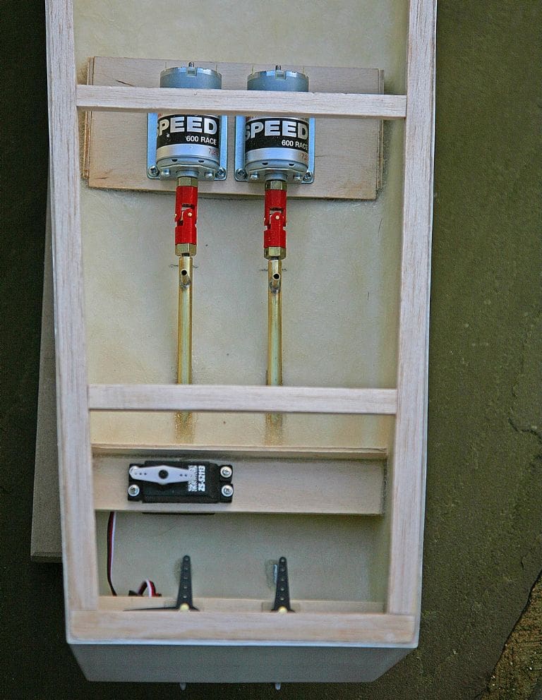
Motor Mounting
It is vital that the motor is secured firmly into the model and correctly aligned with the propeller shaft. Alas, this crucial stage can be ‘glossed over’ or even totally omitted in model instructions. If details are given then they should be followed unless you plan to do things differently, if so do not blame anyone but yourself if things go pear shaped.
There are many ways to install the motor, but a typical one is shown in Figure 7. The motor has a mounting bracket which is secured by screws to a wooden block fitted to the bottom of the hull. The block is shaped so that the motor and propeller tubes will be aligned. To ensure that this is so a rigid connector, (usually a close fitting tube of the same length as the intended coupling), is slipped over these two shafts.
An alternative means of securing the motor is to make a ‘cradle’ from wood into which the motor snugly fits, the motor being held in place by a strap over the motor which is screwed into the mount blocks, Figure 8. With low powered motors, an elastic band stretched between pegs on the sides of the mounting blocks may be adequate to hold the motor in place.
It is possible to ‘glue’ a motor into the hull. Using something like epoxy, this would be very secure but a shade too permanent if you ever needed to remove the motor. A better idea is to use something like Silicone Sealant (as used in plumbing and other domestic jobs). On clean surfaces this sealant makes a strong enough bond for the rigors of sailing but not so strong that a firm and steady force, perhaps aided by a few knife cuts, cannot part the motor from the model.
Couplings
The coupling between motor and propeller shafts comes in many forms and sizes. No one type is inherently better than the others and all can be badly installed to cause no end of problems. The coupling function is to transmit the rotational force from the motor to the propeller shaft with no slippage, minimum friction and accommodate any minor misalignments. If the two shafts never moved out of alignment then a simple rigid coupling could be used. This rarely happens in the real world, let alone in models, and these rigid couplings are best left to experts or at least the very optimistic.
The simplest and also probably the cheapest coupling is a length of flexible tubing which is a tight push fit into both shafts. The unsupported tube between the two shafts ought to be kept to a minimum to avoid twisting and deformation of the tube. Rubber tubing has a tendency to perish over time and the Silicone tubing, as sold in Hobby Shops as fuel tubing, is much better. Although if correctly set up, flexible tube couplings can transmit a surprising amount of power, they are best limited to smaller models.
By far and away the most common type of couplings are those using a ‘Universal’ type of joint. The central part is plastic with brass inserts fitted to the ends which make the connection with the shafts. A grub screw usually connects the coupling to the motor shaft whilst the propeller shaft can be plain and secured with a grub screw or threaded and must have a matching threaded insert. It is vital that these inserts are the correct size and type for the motor and propeller shafts. Incorrect inserts will result in vibration and almost certainly fail at the most inopportune moment!
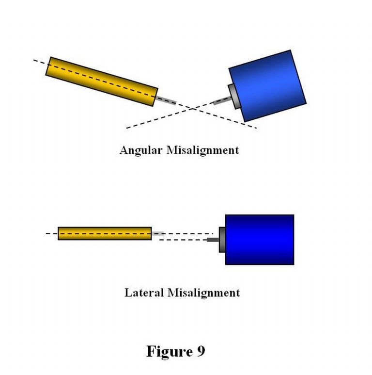
Now the question you have wanted to raise: if the coupling can accommodate misalignment, why go through all the trouble to get the motor shafts as near perfectly in line in the first place? Well, these couplings can only accept a limited amount of angular displacement before they start to protest, usually no more than 10-15 degrees. Rotation is possible at larger angles but significant power loss will occur and the couplings have even been known to show their displeasure by disassembling! If there is any lateral displacement of the two shafts, Figure 9, then these simple couplings cannot cope at all. You can purchase double couplings which can accommodate both angular and lateral displacements but they cost more and take up more space so why not do the job properly in the first place?
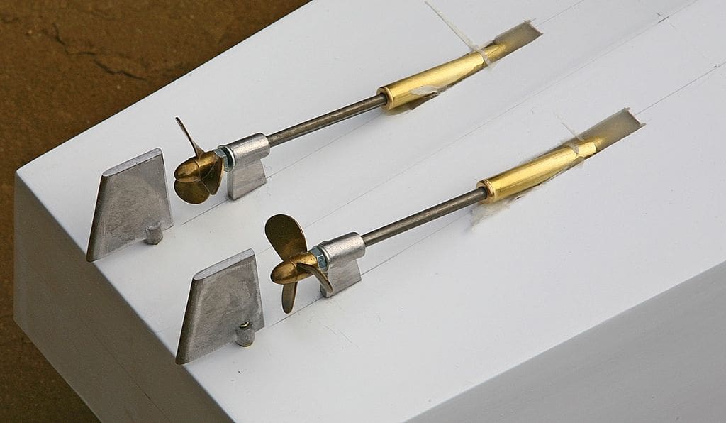
Propellers
Most propellers have a threaded hole in their central boss which will screw onto a matching threaded end of the propeller shaft. This alone would not give a very secure fitting as the forces applied by the motor, especially if applied suddenly, would quickly loosen and unscrew the propeller which would soon be lying at the bottom of the pond!
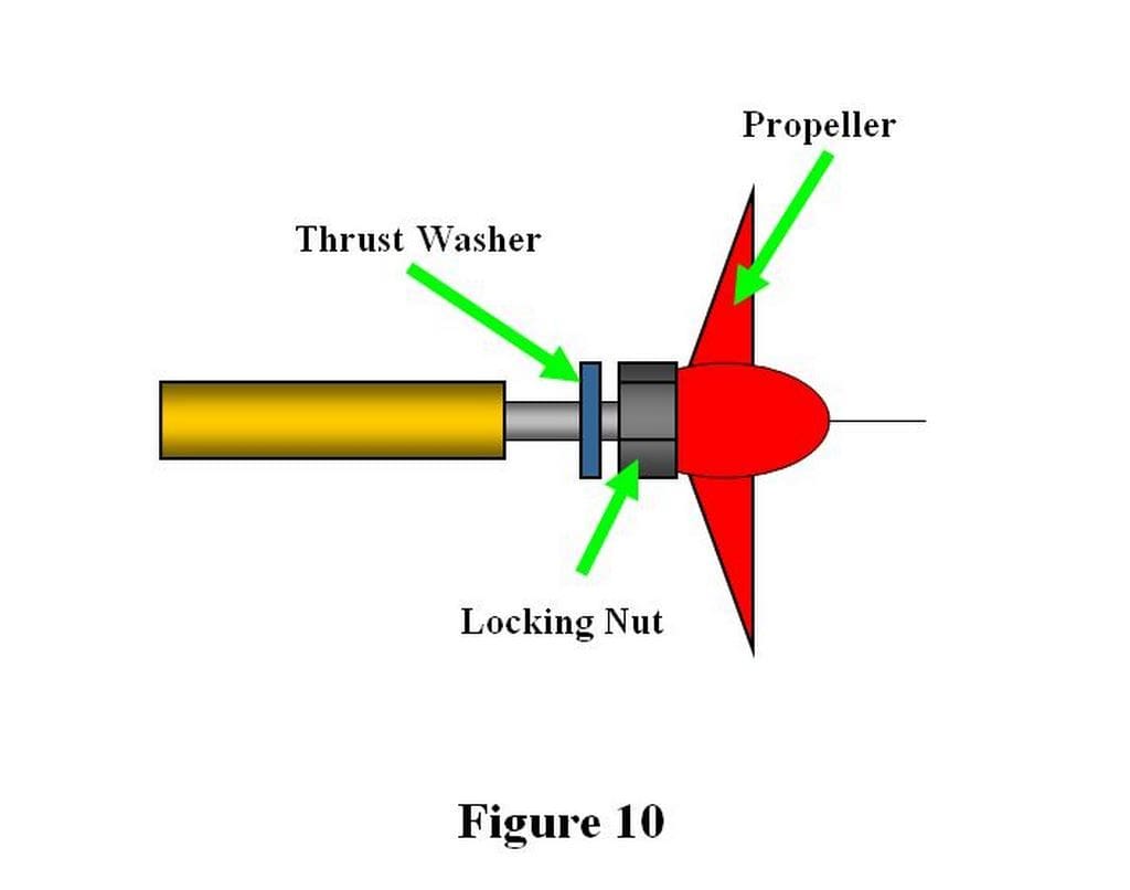
The standard way to secure a threaded propeller top a threaded shaft is to fit a ‘lock nut’ (called a ‘jam nut’ in some parts of the world for reasons that will soon become clear) ahead of the propeller. By holding this nut stationary with the appropriate spanner, the propeller can be tightened up against the nut. You sometimes see modellers trying to use pliers to hold this nut whilst fitting the propeller, not very good practice at all. Finger pressure on the propeller blades is usually sufficient force to ensure a firm and reliable fitting. Ideally, little of the threaded part of the shaft should be visible which ensures that only the plain part of the shaft runs in the close fitting tube bearing. This ought to make a more watertight seal in the bearing and keep friction down. A washer is often fitted ahead of the lock nut so that, when running in the forwards direction, this, not the nut, presses on the tube bearing. Again, this helps to minimise friction, Figure 10.
I did not mention it in the section on couplings but, if the coupling insert is threaded to match the propeller shaft, then it too must be secured with a lock nut. The method is just the same as described for fitting a propeller but this time two spanners must be used, one for the nut, the other for the coupling.
Drive Line Adjustment
It is not enough to just secure the coupling to the motor and propeller shaft then screw the propeller in place. A little careful adjustment will result in a smooth and trouble free drive line.
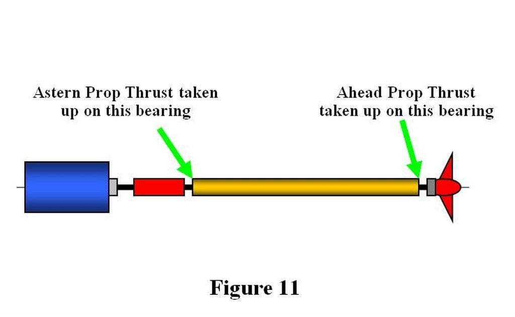
Ideally when the model is going ahead, the propeller’s thrust should be taken up by the thrust washer pressing on the lower tube bearing, Figure 11. This places the wear due to friction on the bearing/washer contact surfaces where it can do little harm. In fact after a little ‘bedding in’ of these surfaces they become very smooth and surprisingly watertight.
Likewise, when running astern, the propeller tries to pull the lower thrust washer away from the lower bearing. This time the force ought to be taken up by the thrust washer behind the coupling lock nut pressing against the upper tube bearing. This is achieved by having a small amount of fore and aft ‘play’ in the propeller shaft. Pushing on the propeller presses the thrust washer at its end onto the lower bearing, pulling on the propeller (i.e. as when moving astern) pull the couplings thrust washer onto the upper bearing. I will suggest that you aim for the smallest amount of ‘play’ possible by adjusting the coupling and/or the propeller positions on the shaft. Less than a millimetre would be best.
On no account should the propeller’s thrust be transmitted along the shaft and reach the motor bearings in most model boat installations. This will cause friction and heat where you least want it and may lead to damage. But, you cry, electric motors are widely used in model aircraft where the propeller is secured to its shaft and hence ‘pulls’ very strongly on the motors front bearing. True, but we usually install the motors the other way around and forwards thrust would be applied to the motors rear bearing which are not intended to accept such forces.
A Frames
Sometimes the lower end of a model propeller shaft is supported by an ‘A Frame’ to emulate full-size practice. If the A Frame is attached to the propeller tube then it is purely functional and the prop thrust can be taken up by the lower bearing as previously described.
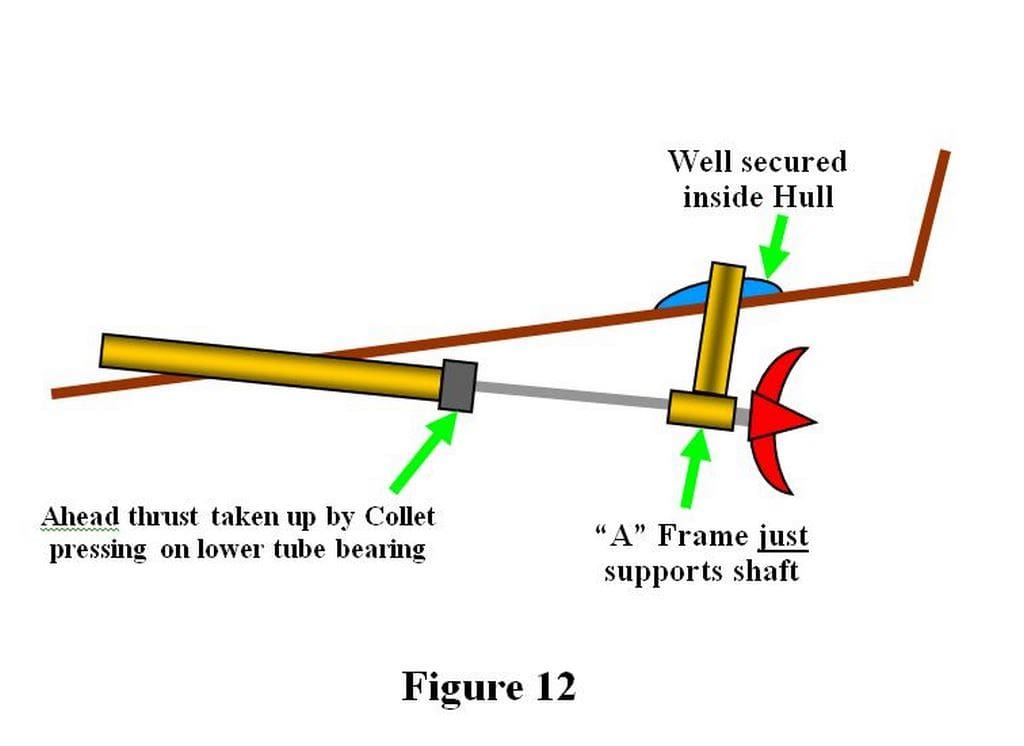
If, in the interests of scale fidelity, the tube stops short of the A Frame and leaves a length of shaft exposed, then things are different, Figure 12. It might be tempting to arrange the propeller thrust to be taken up at the A Frame which could be very foolish. I once experienced a kit to be propelled by two high power motors which featured flimsy plastic A Frames secured to a flexible plastic hull. A Frames are best regarded as decorative items that at most are only asked to support the shaft and any propeller thrust should be taken up by a suitable collet secured to the shaft so that it can press against the lower tube bearing as described before. My advice is to fit the A Frames after the rest of the drive line is installed (and the adhesive has fully set!) and aim for minimum friction.
Lubrication
The bearings at both ends of the propeller tube need some lubrication to minimise wear, friction and probably noise. The simplest method can be to add a spot of oil to these bearings prior to each sailing session and before any out of the water ‘bench testing’! A light machine oil, from the ubiquitous ‘3 in 1’ can, is fine but, for convenience I tend to use a slightly heavier automotive engine oil as there is always some handy in my garage.
Many modellers advocate filling the space between the propeller tube and shaft with a lubricant. This is excellent for ensuring the bearings are always lubricated but is often used to prevent water seeping up the tube and into the hull. If the propeller shaft is a good fit within the tube bearings and the propeller thrust is taken up by the bearings then little, if any water should enter the tube.
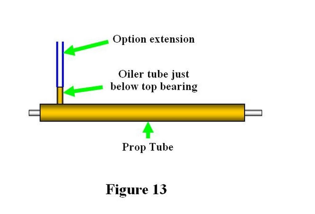
Filling the tube with oil, then inserting the propeller shaft and remaking all the connections can be a messy job, which is assuming that the rudder allows you to withdraw the shaft in the first place. A much neater idea is to fit an ‘oiling tube’ to the propeller tube which allows convenient top ups prior to sailing, Figure 13.
Some tubes may come with an oiling tube already fitted but most don’t. However, fitting such a tube is not a great challenge, using a suitable piece of tubing, drill a hole in the propeller tube to match then secure the oiling tube with solder/epoxy making sure the shaft is not fouled. The location of the oiling tube needs a little thought to avoid problems of access and interfering with other items, somewhere near the upper bearing is usually best. For more convenient topping up a length of flexible tube can be fitted to the oiling tube.
Some modellers insist in filling the propeller tube with grease. This might be an advantage if you have a leaky propeller tube and the thick grease would hinder the inward flow of water. The problem with grease is its viscosity, in other words its ‘stiffness’ and resistance to letting things flow around it. A good illustration of this effect is to take a knife blade and move it edge first through a low viscosity fluid such as water and you will hardly feel any resistance. Now try it through something more viscous like treacle or jam, even with the sharpest of blades you will feel noticeable resistance. The same thing happens inside the propeller tube as the rotating shaft struggles against this viscous drag.
In my less experienced youth, I built a model based on an early torpedo boat. It was outfitted with a motor and battery pack typical of fast electric racing craft and similar performance was expected. In fact it wallowed around the pond in a disappointing fashion and displayed a short battery life and very hot motor. I had of course followed the accepted wisdom of filling the propeller tube with grease. Removing the grease and replacing it with oil resulted in the model storming across the water in a much more realistic manner, a cooler motor and longer powered run. Since then it’s been a ‘no-brainer’ for me to avoid grease filled tubes and only use oil. To be fair, if the propeller shaft has a low rotation speed, perhaps as in a paddlewheel drive, then grease might not be a problem.
Rudders
Compared with the accuracy demanded when installing and setting up the drive line, rudders seem almost easy to install. The danger is that this might lead you into a casual approach to this job and you will pay for it with serious problems later.
The rudder shaft rotates inside a tube that is sometimes just a plain metal, usually brass, tube and other times it’s a moulded plastic item. Either way, the tube must be firmly fixed into the hull, this being to ensure reliable operation and minimise damage to this potentially vulnerable item.
Before doing anything too permanent it is always worth checking that the rudder assembly can move freely in its designed position. Note that this also applies to the tiller arm fitted to the top of the shaft which can sometimes foul internal items or structures. On most models, a rudder movement of 30-40 degrees either side of the neutral position will be adequate. Some thought might also be given to future access to the tiller arm. If the deck is fixed above this arm then you might want to arrange to have part of it removable. Tiller arms in inaccessible places have the perverse habit of working loose at the worst possible moment.
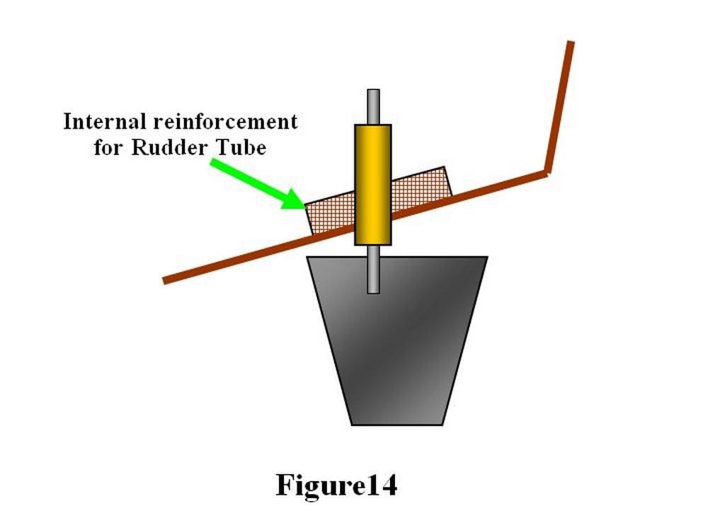
Sometimes it is enough to simply fix the tube into the hull with a suitable adhesive. However, if the hull is thin and potentially flexible then some form of internal reinforcement is wise, this is often just a piece of wood shaped to fit the hull and glued into place on the internal surface, Figure 14.
Some rudder tubes are threaded for a securing nut to be used on the inside of the hull. Again I would advise internal reinforcement with thin hulls and use some adhesive where the tube passes through the hull to ensure a watertight installation.
Lubrication of the shaft inside the rudder tube is a good idea. It will ensure free movement of the rudder and hinder water creeping up the gap between shaft and tube through capillary action. As the movement of the rudder is limited then grease would be satisfactory.
Finally, some people insist that the top of the rudder tube must be above the model’s waterline to prevent water entering. This sounds very sensible but it is no substitute for a close fitting rudder shaft and tube plus some lubrication.
Rudder Linkages
The tiller arm on top of the rudder shaft must have a positive link with the servo arm to minimise any free movement or ‘sloppiness’ which can result in the model having vague steering characteristics. So it is tempting to make the linkage as stiff and tight as possible which then introduces other problems. The rudder servo can end up struggling to overcome the resistive forces in the linkage which results in slower response to transmitter commands. It may not even take up the commanded position before the servo ‘stalls’ as indicated by the always bad sign of a stationary but still buzzing servo. Under these conditions excessive wear in the servos gear train, if not damage, may occur.
What follows are general guidelines, remembering that a kit/plan ought to show a suitable position for the rudder servo and its link to the tiller arm.
Mount the rudder servo so that it is firm with no significant movement when under load.
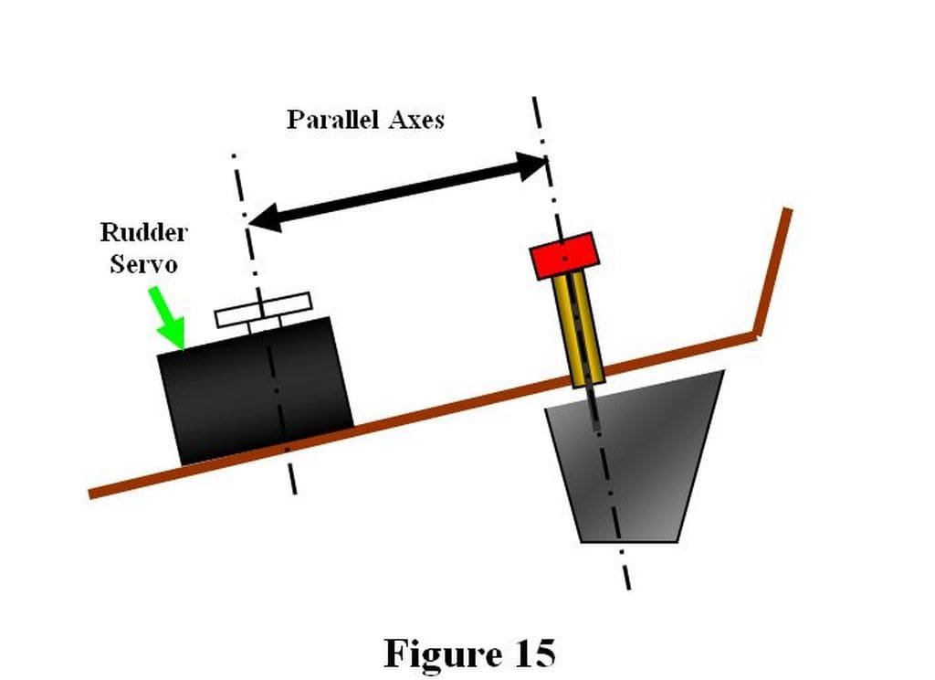
Try to keep the axes of the servo and tiller parallel. Thus, if the rudder shaft is at an angle to the vertical then mount the servo to match, Figure 15. This assists in achieving a smooth motion.
Use as a short and straight a wire link as possible to minimise the risk of the wire bending under load. Commercial push rods are available but any steel or hard drawn brass wire about 1/16 inch (1.5 mm) or a shade more will be suitable for most applications.
Ensure that the link wire is a snug fit in the servo and tiller arm holes.
Secure the wire in the holes to ensure they cannot become detached when in operation. Simple “Z” bends are often used along with clevises on commercial push rods.
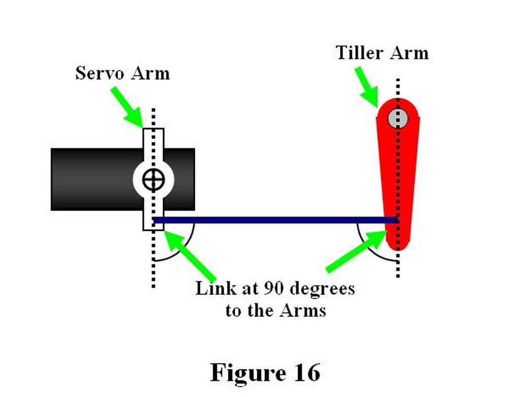
Ensure that the servo and tiller arms are parallel and square to the link when at the neutral position (transmitter stick, trim and rudder centred) Figure 16. This will aid producing even rudder movement in both directions. Adjustable linkages and/or connectors greatly aid this job.
Check and double check that everything is secure, especially if subsequent construction will hinder access to these items!
Internal Installation
Most plans/kits will suggest the placement of internal items such as the battery and radio control gear. You may however find you cannot follow these suggestions because of changes, use of different items or (let’s be honest here) the suggested layout is not practical (I have also encountered some that were actually impossible).
The best approach to this job is to remember that anything that is hard to reach or even inaccessible when the model is completed, will fail sooner rather than later. That’s the way the Universe works and there is little point in arguing with it. So, make sure that you install nothing that cannot be removed easily and safely at a later stage.
It ought to be obvious that all internal items must be fitted so that they cannot move whilst sailing. If they do, at best the model will adopt a comical attitude, at the worst it will founder. Heavy items like Sealed Lead Acid batteries can be held in a simple wood frame glued into the hull. A cut-out in some stiff foam plastic can also secure these items whilst still allowing easy removal.
The whole internal installation needs to be tidy. This not only avoids problems, it can greatly aid any trouble shooting you will inevitably have to do, remember the perverse Universe we live in? The model’s internal wiring is usually worst offender in this respect. Loose wires can easily become entangled with moving things like rudder servos and motor couplings. Try to use as short a length of wiring as possible bearing in mind the need for access and removal of items. Any loose wires inside the hull ought to be tided away into a safe corner and lightly secured there. When opening up a model you should be greeted with a view of a neat and logical layout, not something that appears to be an example of conceptual art!
Following these simple guidelines can make all the difference between a boat which is a joy to operate and one which is a continual cause of frustration.