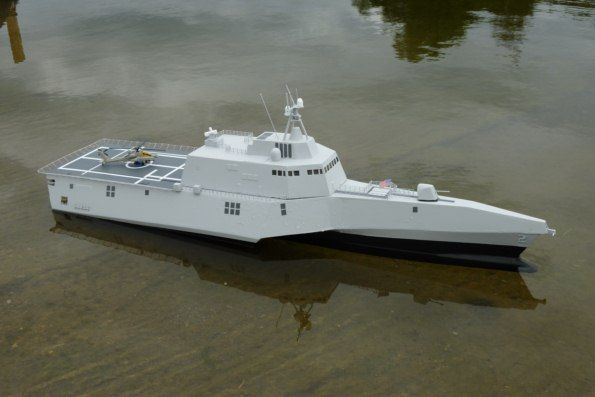
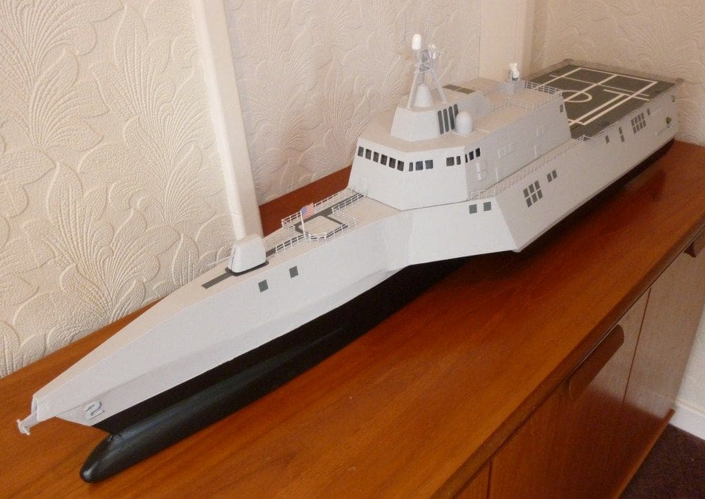
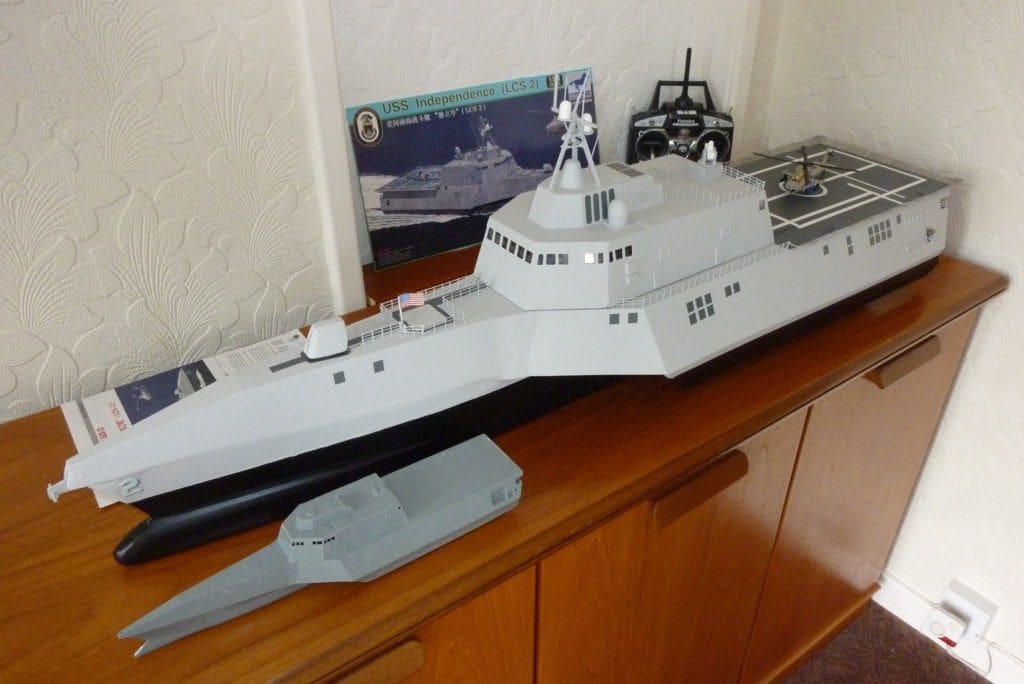
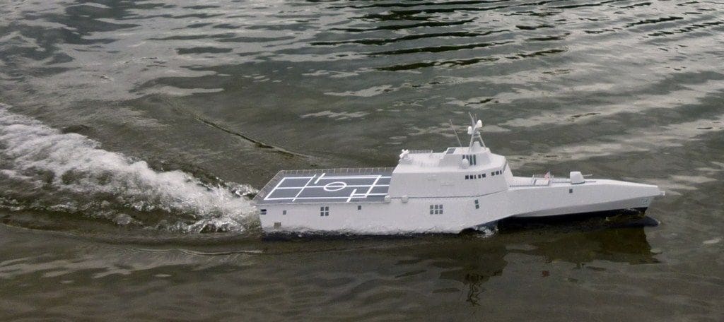
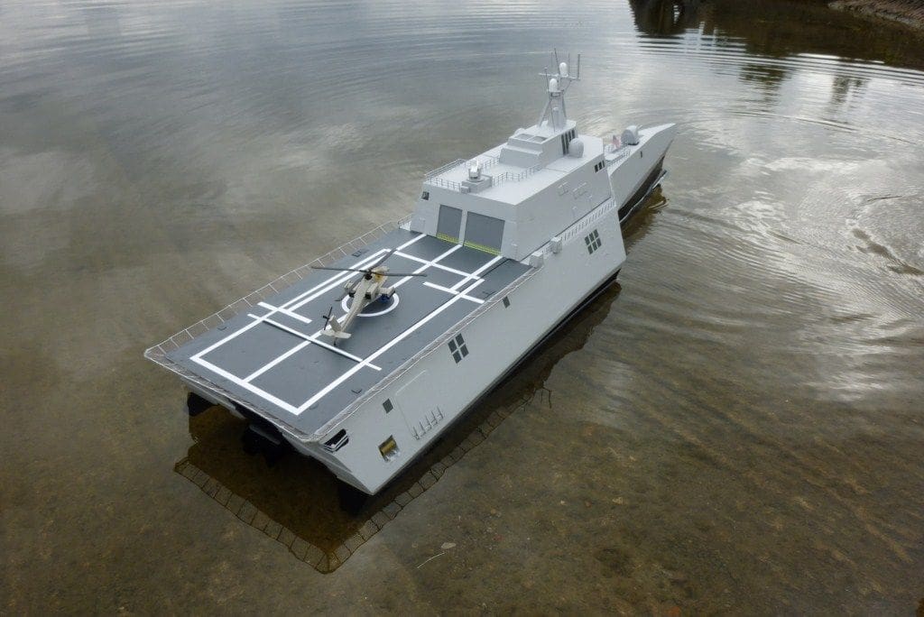
BRIAN JOHNSON builds a water jet powered 1:110 scale Littoral Combat Ship
Principal dimensions
Overall length: 1162mm
Enjoy more Model Boats Magazine reading in the monthly magazine.
Click here to subscribe & save.
Beam: 288mm
The idea
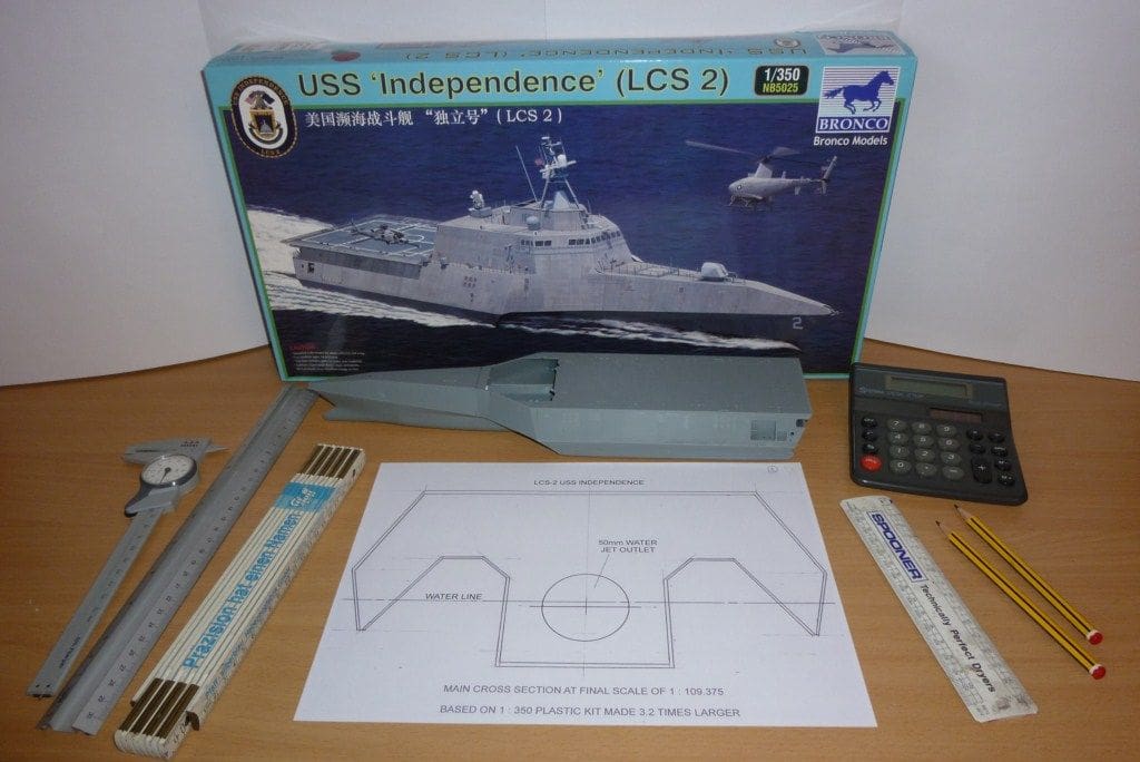
It was January 2011 and the middle of a long winter with new models awaiting trials on more clement days, so what better time than to think of another model? Having established a liking for Graupner 29mm water jet units, both single and twin, installed in four previous models, another one was a distinct possibility. Checking the latest Graupner products showed a new 50mm Water Jet Unit 5 which immediately became the purpose of finding a model to exploit its potential. Around July 2009, some Internet browsing produced a picture of a ship like no other, this being the new USS Independence LCS-2, which had striking looks and was designed for fast multi-purpose duties in coastal waters. In the January 2011 issue of Model Boats the Editor reviewed a 1:350 scale plastic kit of this vessel with the thought that it could be scaled up to make a working model. This seemed to be the perfect solution if it could take the jet unit and was definitely worth a try. Hannants Model Shop, website: www.hannants.co.uk showed two 1:350 scale versions, one by Trumpeter and one by Bronco, the latter of which I purchased. The kit arrived the next day and the seven main hull items were glued together to form the basic model ready for measuring. The result confirmed that it could easily be replicated to any desired scale and a big bonus was the fact that it was designed on stealth lines. This meant that every surface was flat i.e. no curves whatsoever and about 50% of the length was parallel, so some identical bulkheads and flat plywood lengths could give a sound and easy build.
A plan of action
The first task was to fix on a scale and draw a cross section. A handy model boat length is approximately one metre, which is large enough to look good on the water, but small enough to sit on the bench and fit into a car boot. The deciding factors for this model were the width needed for the jet unit along with a round figure for increasing the kit scale and its numerous dimensions. As the jet unit and motor mount would take up a fair length, a central keel to line up the bulkheads was impossible, so two side members would replace the keel and nicely fill the corners in to allow for the only major round surfaces on the model. A cross section was drawn at three times the model size, fitting well on an A4 sheet, and assuming the given 78mm jet unit base width plus the side members, this would need around a 95mm hull width, thus an increase factor of 3.2 was decided on. This was an easy figure for both mental and calculator use with the many forthcoming measurements anticipated. The 1:3 cross-section was scanned into Corel Draw, re-sized to 1:3.2 and printed out for general use. The overall scale, based on the kit scale of 1:350 and a 3.2 increase comes out at 1:109.375 (1.110 in practical terms) which is between the general model accessory scales of handrails etc., but in any event it was intended most small items would be scratch built. The ship length of 127.1 metres thus converts to a model length of 1162mm which was a little larger than anticipated, but it should look good! The beam was calculated at 288mm. It was intended to carefully measure the majority of the plastic kit items to less than 1mm, but as this represents only 110mm in a ship length of 127.1 metres it was not of vital importance, but small detail items and thicknesses would require care.A full size plan view was drawn over three sheets of A3 paper primarily for laying out the drive items within the confines of the narrow main hull, but it also helped to get the feel of the project and fix the locations of the bulkheads. As the work so far showed real promise, the jet unit and electrical items were listed for ordering, with the main items being as per the table.
The next main task was to try and determine whether a hull size at the proposed 3.2 enlargement would float at the correct height with all the electrical gear on board. A biscuit tin with an area of 540 cm/sq with 2.4kg of soup cans inside, immersed the tin by 45mm. The hull area, based on 800mm by 96mm, without the side sponsons, would be 760 cm/sq and the electrical gear plus three sheets of plywood weighed in at 3.14kg. The area has increased by 1.4 (760/540) and the immersion by 1.3 (3.14/2.4) so the new immersion figure would be around 42mm (59/1.4). This water level would be ideal, being just above the desired centre line of the jet outlet used as a basis for previous water jet models and ballast could be used if further immersion was required.
Last but not least, the electrics were coupled up and bench tested. With this carried out the mechanical side could be mentally put to one side and all efforts put into construction.

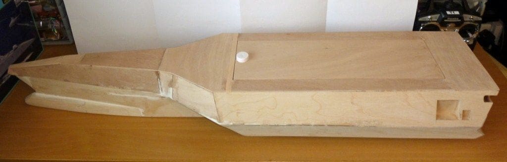
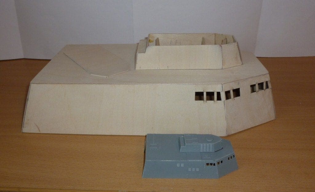
Phase 1: The flat top basic hull
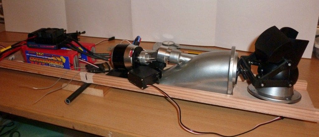
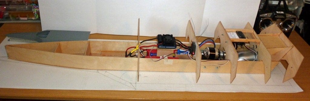
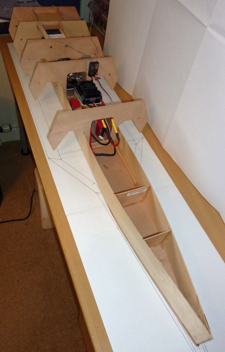
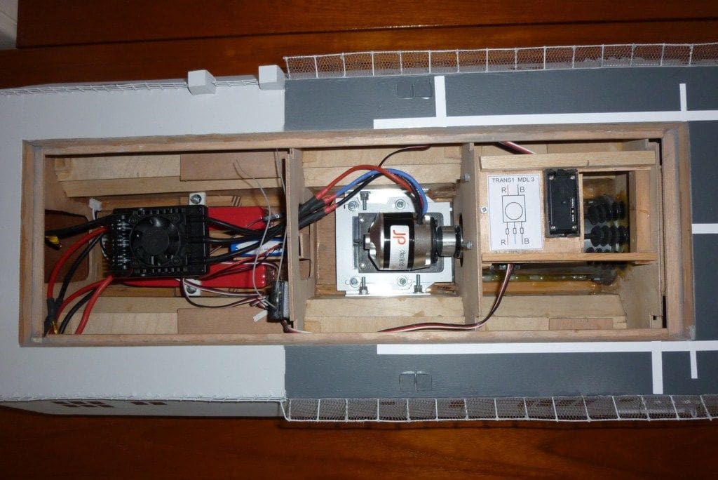
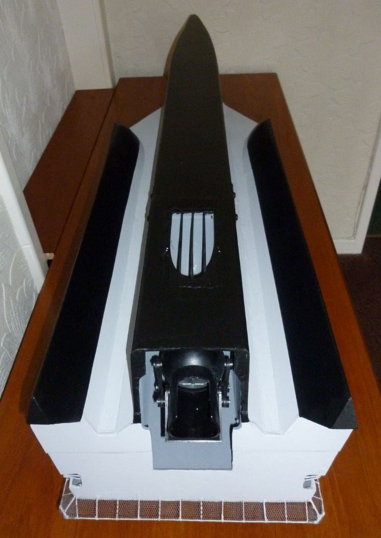
Now being satisfied that the size, weight and immersion were all feasible, plywood cutting could commence. A cross section print was cut out and used as a template for five 3mm identical, but oversize, bulkheads. These were then held together using two 6mm tapered dowels (from old paint brushes) and filed to the template as a block. The central areas would be cut out later to suit whatever was passing through each bulkhead. The 3mm thick x 96mm wide hull baseplate with its two 12.5 x 9.5mm hardwood side supports along with the bulkheads would form the basic skeleton for the plywood cladding, but the bulkheads would require spacing to suit the driveline items. Commencing from the rear of the model, the jet unit with its motor and reversing bucket was placed just forward of the sloping stern line to protect it from damage if the model was stood on end, plus it would not spoil the scale appearance when viewed from above. Next along the base were the batteries and these fitted nicely on edge and were moved forward and back to give a very approximate C of G. All other items have little effect on the model’s balance, so the bulkheads were fitted to clear the drive items after suitable cut-outs were made and the base slotted for the jet inlet duct. The hull side sheets were glued to the baseplate and bulkheads, but leaving spare at the stern and bringing the sides together at the bow and two extra bulkheads were fitted to maintain the front curvature.
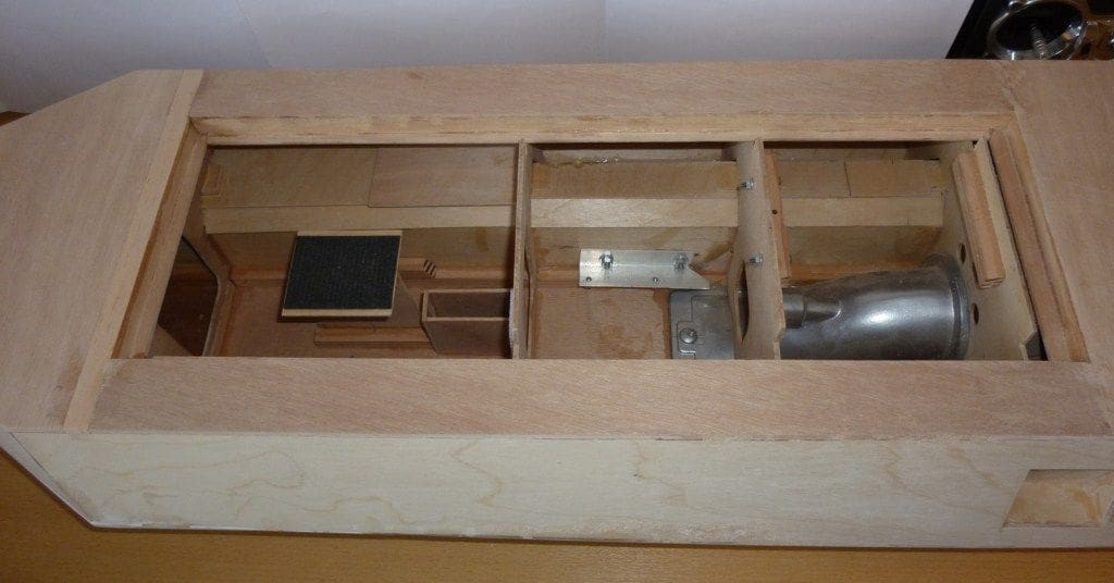
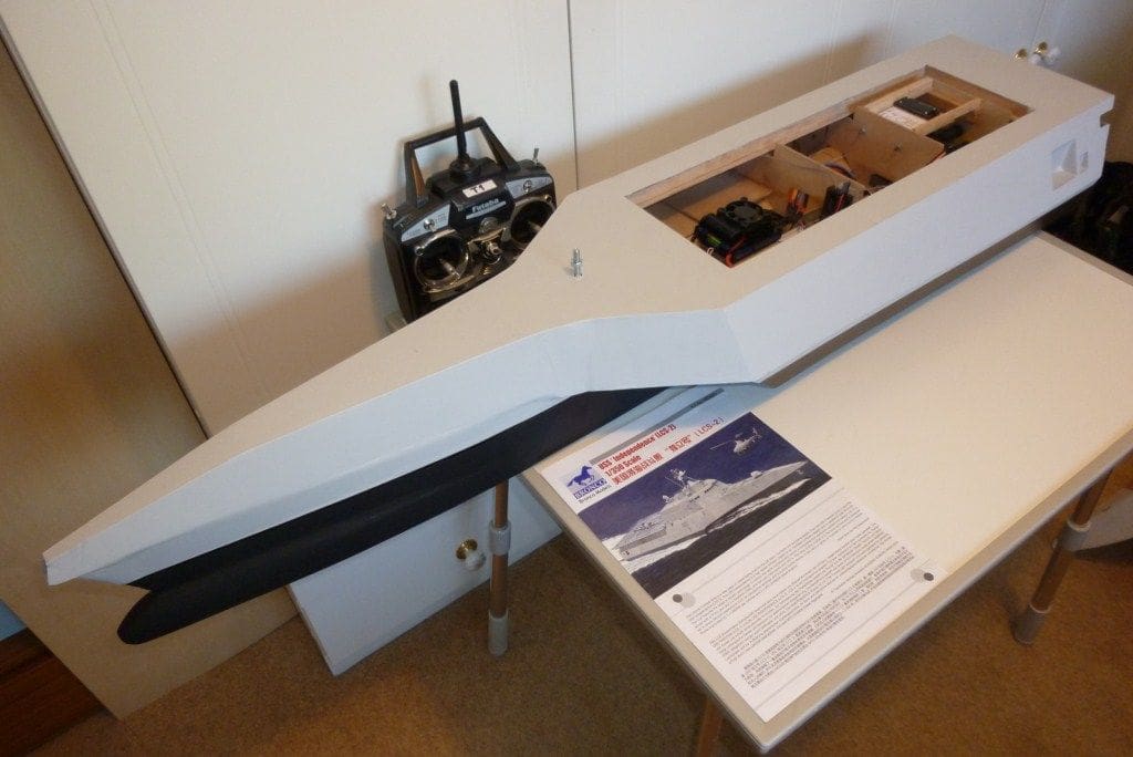
The hull was now a box and ready for fitting out, with the jet unit being the main job, so this was epoxied to the hull’s base and the rear bulkhead. The stern was fitted at the correct angle and the jet outlet area boxed in to the rear bulkhead and sealed off. The steering servo with two pushrods and the reversing bucket servo had little room for mounting, so the only way was to fit them upside down on a platform just underneath the deck. Three 15mm holes were drilled through the bulkhead in line with the jet swivel connectors which then settled the servo platform height to allow for horizontal push rods. As the bellows would have to be fitted at a later date, the pushrods were made as two lengths with the front portions fixed to the servo arms and the rear portions fixed to the jet connecters with middle overlaps for setting and securing on final assembly. Brass inserts and grub screws from 5 amp connection blocks would then be used as the through holes allowed just sufficient room for sliding on and locking.The angled jet drive motor on a support plate was slung between two aluminium angle pieces fixed to the hull sides by M4 screws and nuts. Slight adjustment and filing of various holes was required to settle the motor shaft in line with the coupling and jet drive shaft.
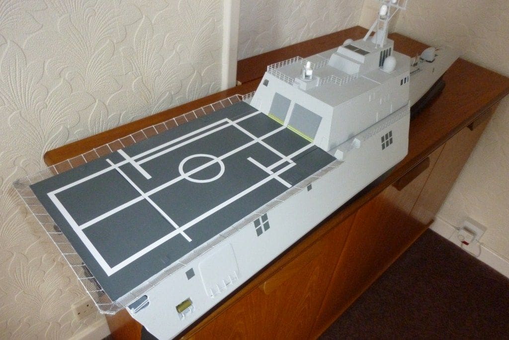
The speed controller was mounted on a platform just below deck level which left room underneath it for a battery each side secured by clamps and M4 fixings. The receiver and controller battery also fitted into this bay and all the cables connected together without needing any extensions other than a short one for the steering bucket servo. The hull sides and sponsons, with slightly falling lines from front to rear due to the off-scale hull, were plywood clad and all joints sealed before the deck was added. As the full deck area had to be flat (for helicopter use) the 480mm by 150mm hatch aperture was fitted with a set-in coaming for water sealing to suit the stiffening surround on the hatch itself.
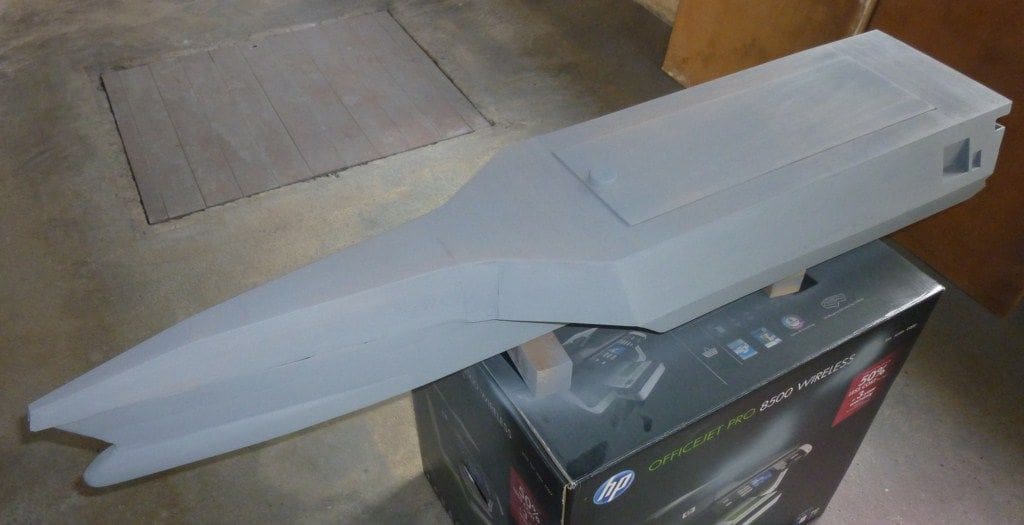
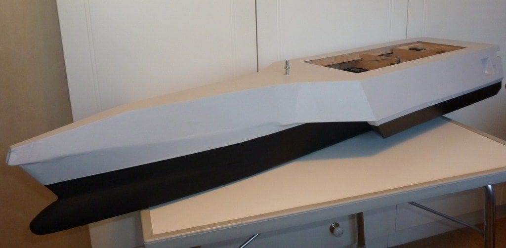
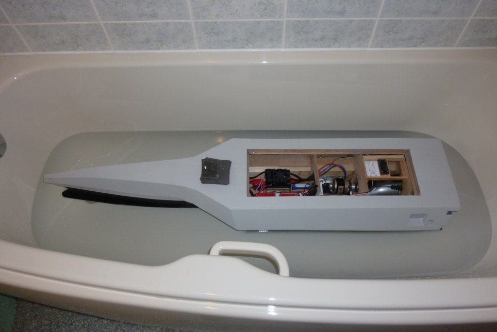
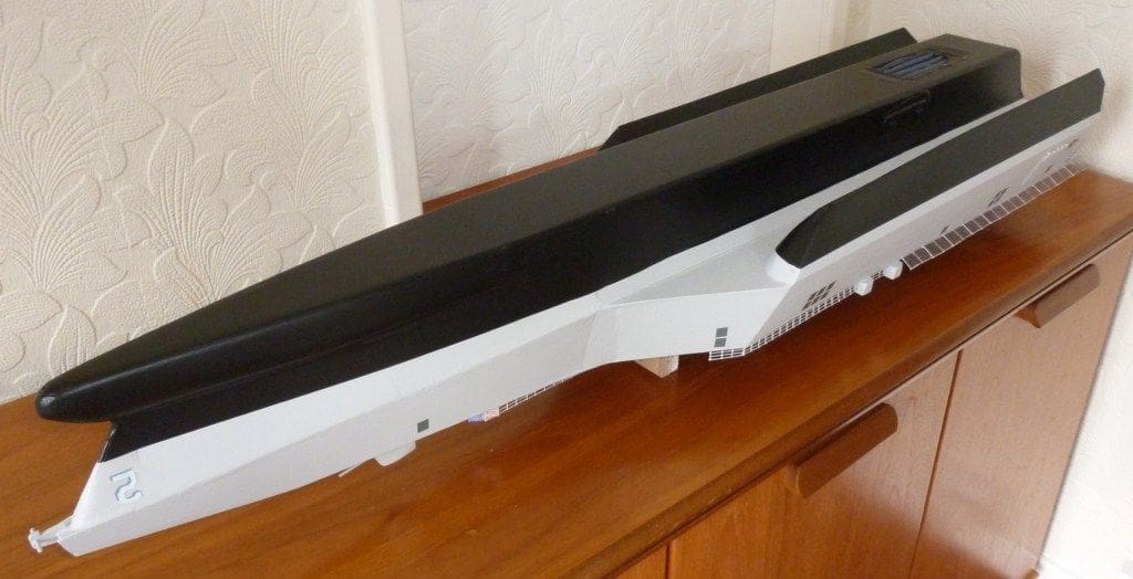
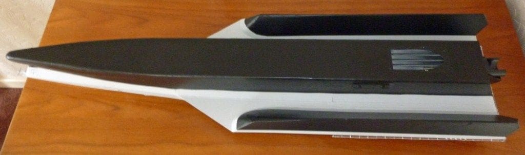
The underwater bulbous front portions are of balsa glued on as blocks and sanded to shape afterwards. At this stage, with the completed hull unpainted and not fully sealed, I was eager to know if it would float anywhere near the desired waterline level. The hull weighed 2640 grams and all the electrics in the biscuit tin, weighed 1965 grams so the hull with 2020 grams of soup cans inside was wrapped in two wheelie bin rubbish bags ready for the bath test. With an approximately level deck, the water level was about 20mm above the jet outlet centre line and the waterline was about 10mm above the scale water level. As the soup cans were not necessarily in the best C of G position and a bin bag started leaking (!) a further re-test after painting and fitting out was thought advisable to ensure more accurate readings. Achieving the balance between the right scale water level for the model and the optimum level for the jet unit was only guesswork, so the 10mm disparity was accepted. The plastic kit was moulded in a flat grey colour which is not available in the Halfords 500ml car spray can range, but their grey primer was a very good match, so three coats made it look fairly respectable with the intention of more coats after final sanding and joint sealing.
Fitting out, painting and first trials
This was straightforward, commencing from the rear by inserting the propeller shaft through to the front ball bearing race and the three servo push rods through the holes in the bulkhead. The jet outlet nozzle with its reversing bucket was secured using the M4 screws provided. Graupner were unable to supply the sealing gasket, but a vehicle wheel inner tube was easily cut and grease used each side for additional sealing. The three bellows were slipped onto the push rods and epoxied to the bulkhead to ensure a good water seal before the servo platform was fitted. The five amp connection blocks bridged the push rod ends for fully tightening-up after powering the servos and checking the travel. All the rest of the gear was re-installed and checked for operation ready for the next bath test.With a near final weight of 4300 grams, the second bath test showed the model to be floating stern down, but 1kg of soup cans near the front gave the same 10mm above the scale water level of the first test. Lead sheet ballast could easily be fitted close to the superstructure front to achieve the best running and stationary level. Once again leaks appeared inside the hull rear and at a sponson seam, so further sealing was required before a third check could be made. By this time, and after further coats of primer, the grey finish was looking decidedly sad and patchy and fine sanding made it worse still, so Plan B came into operation.
This was to use a brushed on matt (or similar) paint or even household emulsion. Any form of painting is, for me at least, by far the least enjoyable of all modelling activities, but the size and look of the model demanded and deserved this unwanted task. Dulux Grey Steel 2 Kitchen matt emulsion provided the answer. This is a slightly lighter shade than desired, but very acceptable in the circumstances. The underwater surfaces of the hull and sponsons were to be matt black and with nearly all this area being flat panels, vinyl sheet filled the bill and no masking off was required. The small curved areas of the main nose and sponson noses plus the stern and motor mount clamp plates were painted over with Revell silk matt black to match the vinyl and this completed the hull.A final bath test with 755 grams of lead sheet, close up to the main cabin front for maximum effect, gave the same slightly nose up attitude but it was sufficient for a trial run pending the making and fitting of the superstructure. A fine 2011 June day prompted the first powered runs and I was pleasantly surprised to find the model had two distinct running styles.
The real ship is designed to be much faster than other warships with a speed in excess of 44 knots and the model in spite of its size and weight, when on very little throttle, soon moves faster than a realistic looking speed suitable to its scale, and with less than half throttle, it became a very fast model power boat! So, the original selection of the 50mm water jet on 22.2 volts was obviously providing too much thrust for the model, but it was nice to have spare power for more extended runs later.
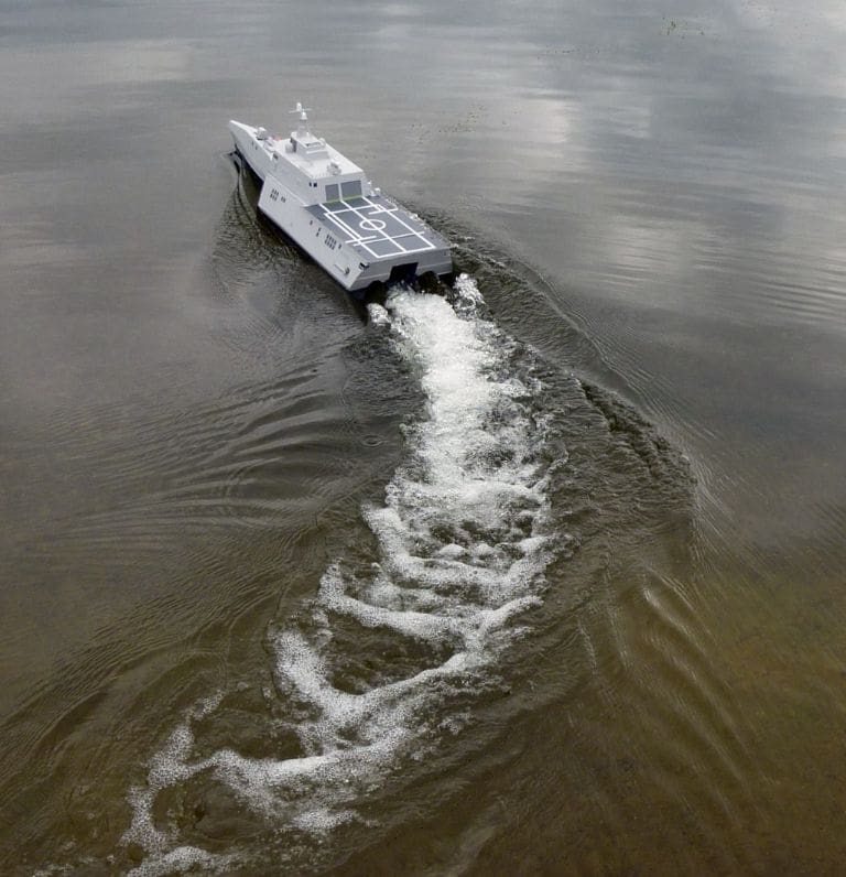
On its admittedly short trial runs it was very stable laterally on turns and the wake, along with the rear jet outlet, gave a satisfying display and appearance. The real vessel, being designed for helicopter use, has to remain level at all times and the model, due to its long and parallel box shape, did just that and no lifting at speed was noticed. Presumably the builders of large model warships take this for granted, but after a diet of airboats and launches with lifting bows this level ride was a novelty. The full size vessel has small front and rear stub wings which may be used as ailerons to constantly trim its stance to cater for its helicopter role.
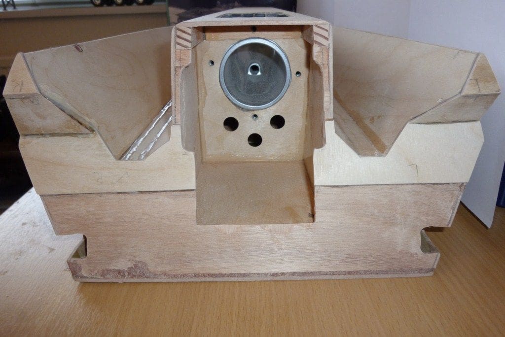
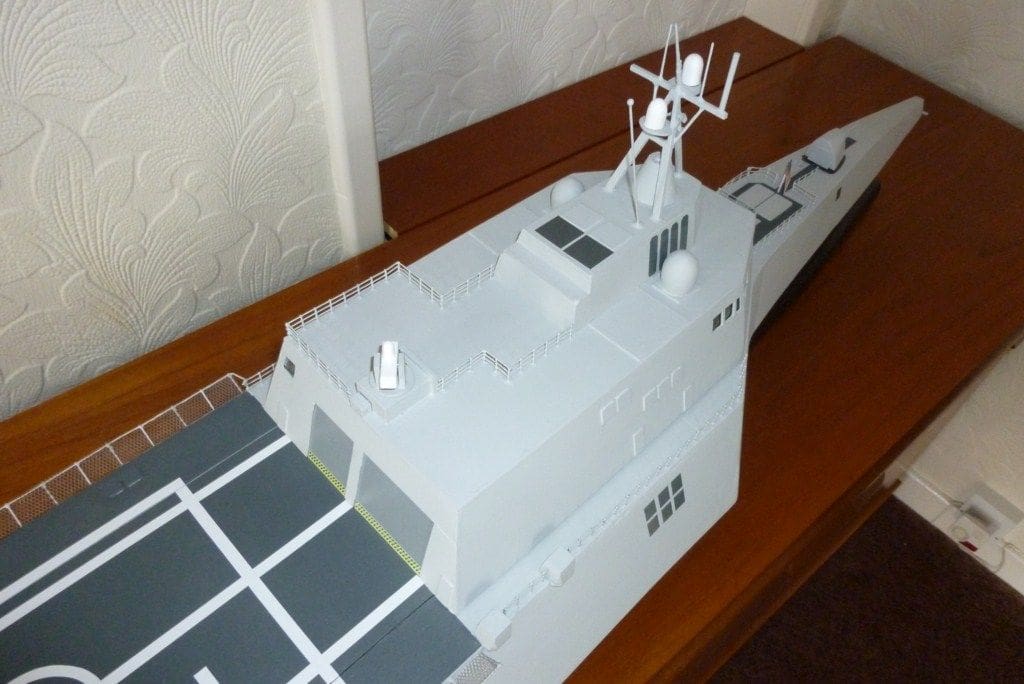
Phase 2: The superstructure and final items
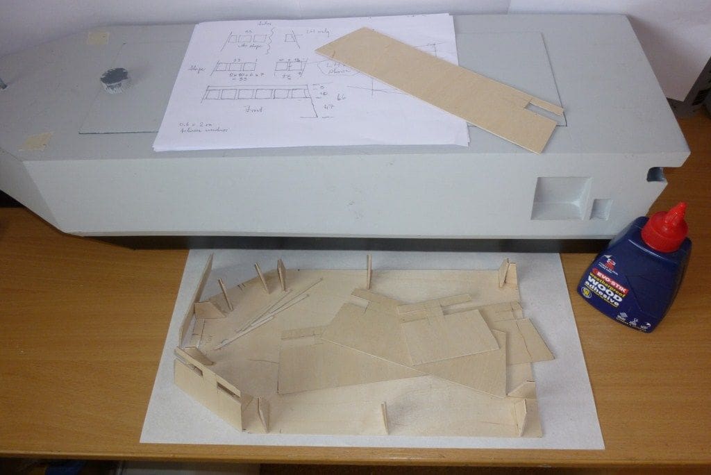
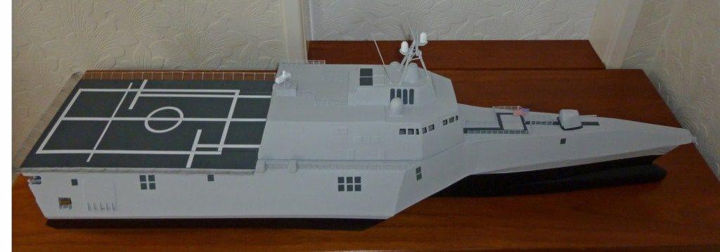
Having a flat top deck and a large flush hatch had the advantage that the superstructure could be made, assembled on to the hatch, and painted independently of the large finished hull. The base unit of the superstructure was again all of flat side panels and all six sections sloped inwards at the same 15 degree angle which made life easier. A baseplate cut to the base unit plan profile with 14 gussets cut at 15 degrees spaced round the perimeter allowed the side sections to be easily trimmed to length and glued on after the window slots were cut and the rear hangar doors fitted. The front portion of the baseplate was cut away to allow later access to the window areas so that sections of clear acrylic sheet could be inserted, thus avoiding the need for masking-off during painting.
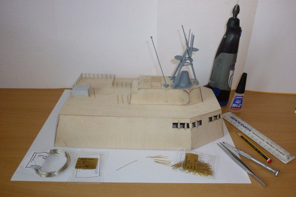
The top part of the superstructure was made in the same way as the lower portion. Measuring the plastic kit parts then became very important as the ‘A’ frame radar mast was made up of small parts and the right proportions were needed to give a valid appearance so the oddment box was usefully raided.
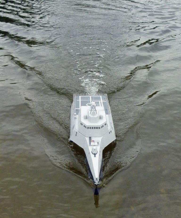
Extensive hand rails were required and 1:96 was the nearest available to the model’s 1:110 scale. James Lane of Display Models supplied Type C three rail brass stanchions and 22swg tinned copper wire for the rails which were easily fitted after drilling 0.8mm holes in the decks and securing the stanchions with a spot of superglue. The scale difference is not readily apparent, but the hand rail appearance does illustrate the scale while enhancing the finished model. Display Models also supplied Type A 1:48 stanchions for the perimeter of the rear deck area and a 22swg piano wire rail was used at the rear for added strength during handling. The safety net, added later, is synthetic mesh found at a material remnant shop. All this finished the model’s construction, so some coats of emulsion completed it before adding the darker areas on the front and rear decking.
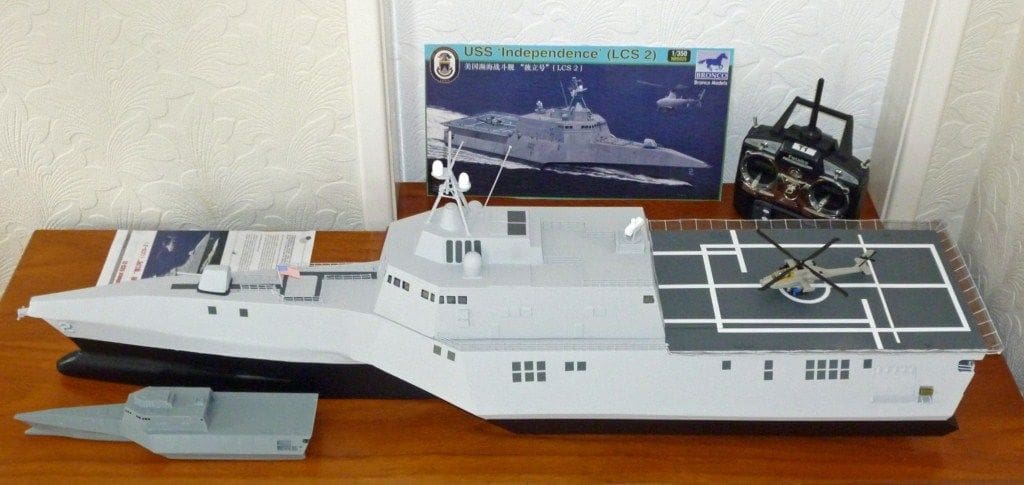
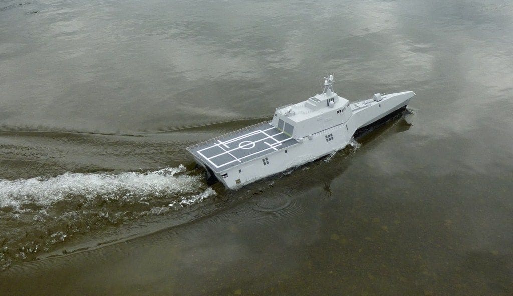
Blanking off these areas allowed the use of Tamiya spray paint, Ref: TS-67, which provided a good contrast to the vinyl sheet white lining on the rear deck, fitted after the superstructure was epoxied to the hatch. The yellow and black safety edges on the hangar doors were a measure and make job too far, so the kit decals including the flag and bow numbers were scanned into Corel Draw, enlarged by 3.2, and printed on to photo paper ready for gluing with Evo-Stik. To further illustrate the scale, a Revell ‘easy kit’ Apache helicopter was found and put together. This is 1:100 scale, but still looks good on the flight deck. Its radome had to be removed as this would obviously foul the hangar door if moved inside for stowage and the violent yellow and black camouflage was covered over by navy grey.
The total model weight came out at 5780 grams including the ballast which actually matched the weight of my previous Riva Aquarama launch that needed lots of throttle for a good performance, so the larger jet unit and 22.2 volts was worthwhile. Having the finished and painted model and comparing it with the few good photos available of the real thing highlighted some notable differences. These were that the actual vessel has many small items set in, and protruding from, the hull and superstructure and these break up the large areas. It is impossible to reproduce all these small features, but what has been made is exactly to scale above the waterline and modified below it to suit the water jet unit.
Phase 3: Water trials
After six month’s work and two bath trials it was time to really test its potential with a mixture of elation and trepidation, but nevertheless still eagerly awaited!
The test actually consisted of confirming and extending the earlier trials. A small movement of the throttle gave a nice sedate run and slightly more movement gave what I imagined to be scale cruising and operating speeds. Approximately half throttle produced an indecently high speed which made nonsense of its role as a good looking scale model and full throttle was not even considered!
More ballast had been added to the front of the cabin and the stern was still slightly down, but this had no effect on the running. Reversing, using the bucket over the outlet nozzle, was not very effective, but no doubt further use will prove otherwise. The model appeared to be laterally stable at all times when turning, so nothing dramatic disturbed the pleasure of just using it. The only clue to higher speeds was the addition of a pronounced wake from the front of the sponsons to join the front and rear wakes. The reason being that the sponson fronts are fairly blunt and a sharper edge would help. Some ballast was removed and the slightly tapered sponsons finished up being partly immersed at the front and almost submerged at the rear, this presumably due to the overall weight increase during the building. The ideal set-up is for the sponsons only part entering the water to provide lateral stability, but more care would then be required on high speed turns. Due to its potential for much higher speeds, the thought came for it to have an instant conversion kit to make it look to be a larger scale and therefore more credible for fast runs. A new lift off superstructure and hatch cover to a nominal 1:10 scale with a streamlined cabin and rear sundeck would make an attractive model for any speed and wood cutting nearly commenced before common sense prevailed. The forward gun could have a lift off cover and the extensive too low hand railing would spoil the effect, but the concept of a fast flat top hull with varying scale lift-off tops is still valid. The making of this trimaran after a series of mono hulls has been very much enjoyed, if prolonged due to lots of measuring, and it has resulted in a strong and striking looking model from all angles.
(The concept of using a commercial plastic kit as the basis for then designing and building a much larger working model is not new. It is relatively easy way of constructing a practical r/c model and of course the range of prototypes in the marketplace as small plastic kits is huge. Brian is to be commended for his resourcefulness and ingenuity. The Riva Aquarama he refers to was in September 2011 Model Boats – Editor)
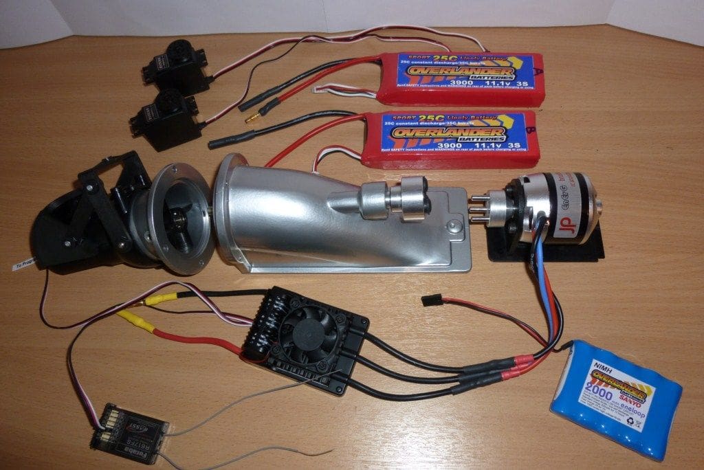
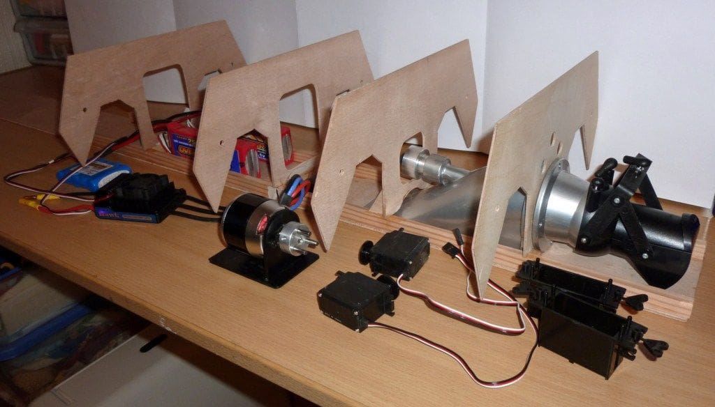
Materials for USS Independence: scale 1:110
Graupner Jet Unit 5 (Ref 2347) with steering nozzle and reversing bucket.
This 50mm unit has two ball bearing races for the propshaft and is supplied fully assembled ready for mounting to the stern bulkhead.
JP EnErG C60 Brushless Motor with 6mm output shaft.
The connector sizes are 3.5mm gold and matching connectors are supplied loose for soldering to the controller output leads. This motor was used on the previous Work Boat and Riva models on 14.8 volt batteries, but it was thought that this model would demand the full 22.2 volts available.
Graupner Motor Mount (Ref 2395.1) complete with mounting screws.
This mount was designed for the 29mm Jet Unit 6 but a plinth could be made to suit the new unit centre height and the two mounting holes opened up to suit the C60 motor.
Graupner coupling (Ref 2221.1).
Three pin coupling single for 6mm input and 7mm output shafts.
Batteries: Overlander 3 cell LiPo 11.1 volts 3900mAh.
To be coupled in series for 22.2 volts to controller and motor.
Brushless controller by Fusion Hawk, 100 amps with integral cooling fan.
This is not a BEC type controller so an Overlander NiMH 6 volt 2000mAh battery was used to power the receiver.
Futaba 2.4 GHz R617FS 8 channel receiver.
A three channel unit would suffice, but other functions could be added later if desired.
Two Futaba S3152 servos and cradles.
Graupner recommend an output torque of more than 5 kg/cm. The S3152 is rated at 6.33 kg/cm which should be sufficient.
Three flexible bellows.
These are for the servos with 3.5 and 12mm ends and 50mm long.
Plywood sheets.
1/8 inch for the main hull.
3/32 inch for cladding.
1/16 inch for the superstructure.


