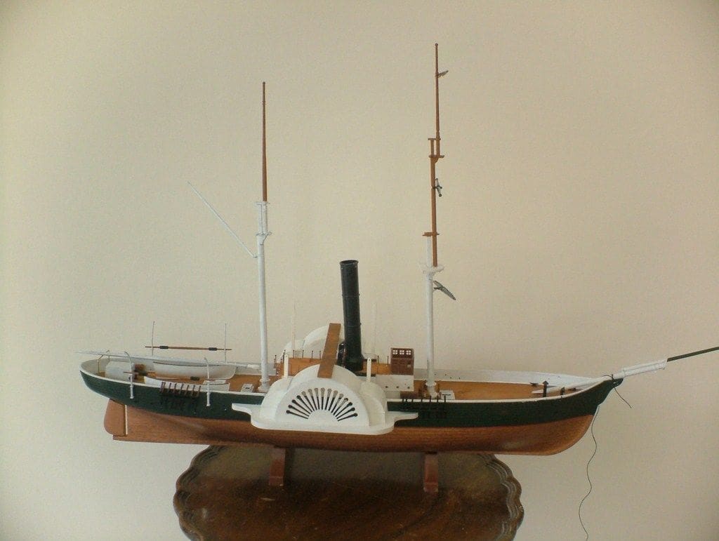
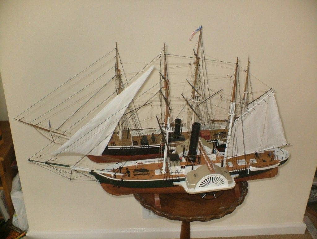
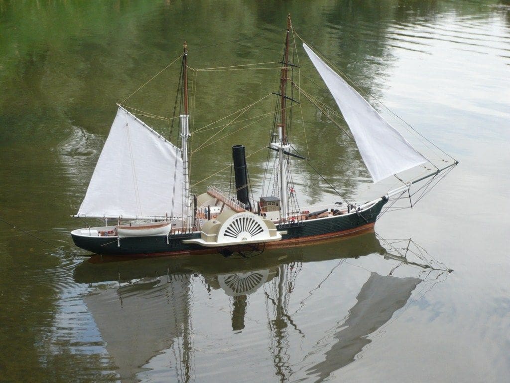
Dr MARCUS ROOKS converts the Revell USS Kearsarge into this revenue cutter
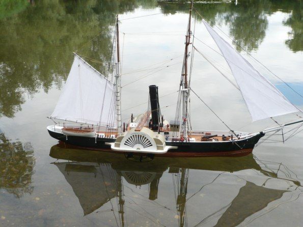
Not many ships have the distinction of being abandoned at sea whilst still considered seaworthy, but such a fate however was to await the US Revenue Cutter Harriet Lane. Admittedly, not one of the world’s more famous vessels but she deserves a mention on account of her illustrious career during the American Civil War.
Enjoy more Model Boats Magazine reading in the monthly magazine.
Click here to subscribe & save.
She started life in 1857 as a United States Revenue Cutter, named after the niece of the future president, James Buchanan. At the outbreak of the Civil War she was drafted into the Union Navy, seeing extensive action at Fort Sumpter, Galveston, New Orleans, Texas and Virginia Point.
In January 1863 whilst almost all the Union fleet (including Harriet Lane) was anchored in Galveston Channel, Confederate troops opened fire on the fleet and attempted to board the Union ships. Harriet Lane was boarded by Confederate forces and raked by gunfire killing her captain, then rammed by a Confederate ship and captured.
After a week of repairs, Harriet Lane was re-commissioned into the Confederate Navy. She was used as a blockade runner taking cotton to Cuba, but was pursued and overtaken by Union ships which then waited for her in Havana. In the resulting chaos, Harriet Lane in an attempt to escape, was grounded and then refloated by the Union forces but declared unfit for future naval action.
She was refitted as the three masted schooner Elliot Ritchie and operated out of Philadelphia, but in 1881 after a fire in one of her cargo holds she was abandoned to the sea. Thus , an interesting service career for this ship!
Getting started
I had the remains of a Revell USS Kearsarge, having used some of it on my abortive efforts at converting another one to steam power, so what to do with all this? I initially thought that converting her to the CSS Alabama would be rather nice as it would then make a sparring partner for USS Kearsarge. So, I carried out my usual trawl of the internet to gain information which was readily available for CSS Alabama. However, during my search I came across another Civil War ship, the Harriet Lane, and hence this model.
I remembered as a boy making a small version so I started to think about somehow modifying USS Kearsarge to Harriet Lane. Looking at the available information she was only about 180 feet long so the hull would have to be shortened and the front end was entirely different in appearance, but her beam and draft were very similar so I would not have to make any adjustments to these dimensions. She was a two masted cutter, the masts being closer together than USS Kearsarge and the mizzen mast was much taller and the sail considerably bigger.
The biggest difference was the fact that she was a paddle rather than a screw driven ship. Having recently completed SS Great Western I was keen to attempt another paddle steamer, learning from my previous mistakes! In this case unfortunately there were no suitable paddle wheels so I would have to make them from scratch. Did I trepan them from flat, build up from stock material, or obtain some from another kit? The only possible donor would be Zvezda’s 1:100 version of SS Sirius, however at a cost of £40 I thought this was too much to pay for just the wheels and the kit would be ruined, unless of course I bought yet another kit for the wheels!
I thought that the Graupner paddle wheels may be useable but at 140mm diameter they are far too large. In the end I thought that I would try constructing them from brass rod, bent and soldered to shape. I had recently come across a model of an early paddle engine and wheels which seems to have been built this way. I also decided to install electric drive rather than try anything too fancy.
There are no photographs of Harriet Lane and only a handful of lithographs. None of these are consistent, showing different front ends, arrangements of paddles etc., so I would have to amalgamate them all to obtain a composite result. There are a number of wooden kits of Harriet Lane, but these also suffer from the same defects.
Anyway, enough of this and on to construction. With such a conversion, once the initial cut had been made, the path was set and there was no going back, especially as I was far from certain that I would be able to complete such a conversion.
The hull
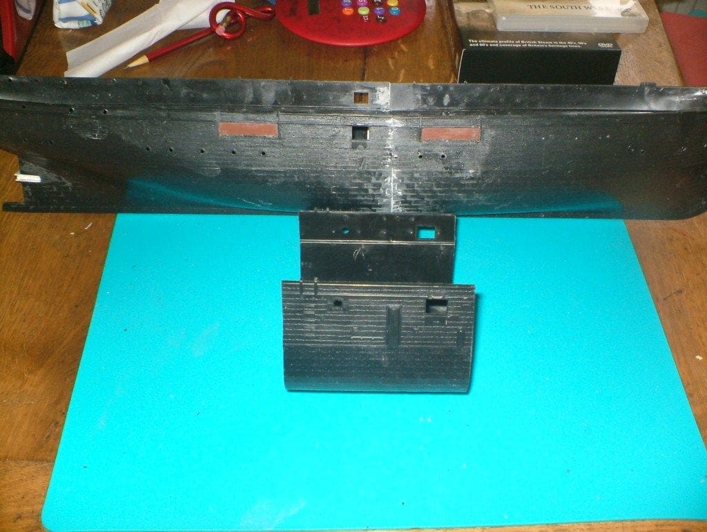
I started with the hull as this would need the most alterations and I had to go back to my schoolboy mathematics for a time. The full size USS Kearsarge was about 210ft long and the model hull was 32ins long. Harriet lane was 180ft long, so how long would the model hull be? Answer; about 28ins, thus I would have to remove approx. 4ins from the hull.
This is where a little luck comes in handy as when such a large amount is cut from the middle of a hull, would the two ends mate satisfactorily? Visually they looked as if they would if cut from the centre of the hull where the hull seemed to be relatively parallel. I applied luggage tape to these areas and marked the cut lines and surgically butchered the hull. Yes, just as easy as that!
To my great relief the cut ends mated remarkably well; there was just a slight step on the top of the gunwales that would be covered by the paddle boxes. I made a joint strap from thin styrene sheet and cemented it into one half. When set I joined the other half, holding them together with small clamps until fully hardened. It was already looking good so I could now attend to both ends of the hull.
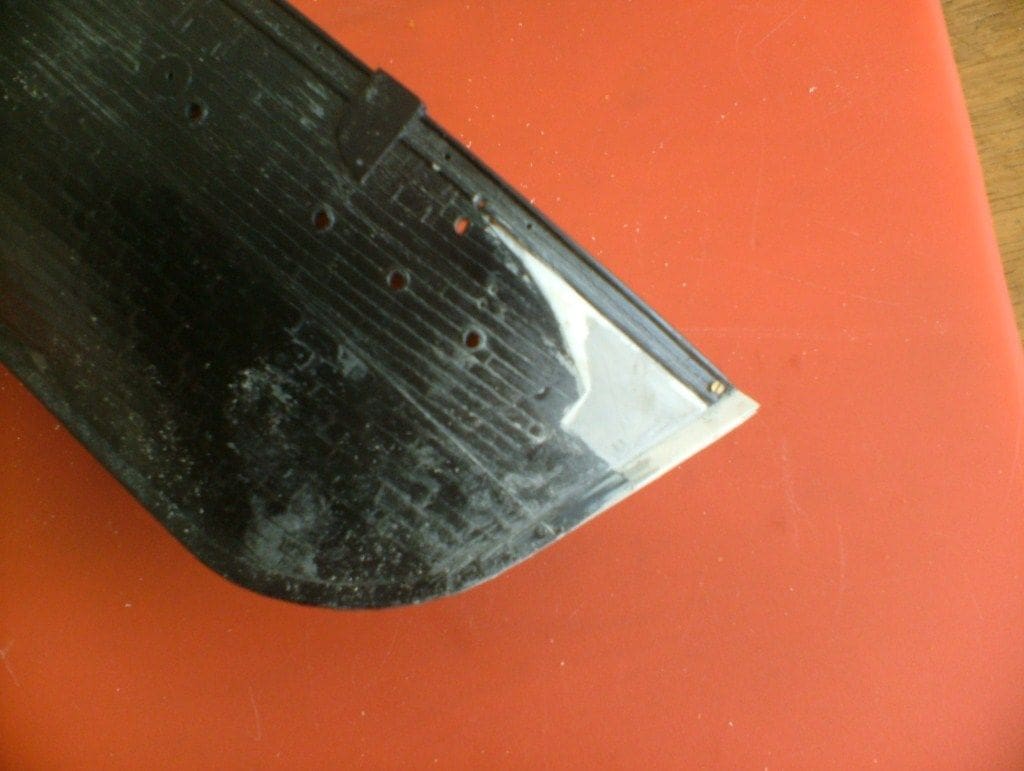
Aft first: We no longer needed the propeller bulge but we did need the rudder that was fixed, which was of no use to me. I cut away the rudder and opened up the rudder space. A new hole for the rudder tube was drilled nearer the stern post and continued into the keel skeg. The old hole was blanked off and filled with putty. A new larger rudder was made from two pieces of styrene sheet cemented to together. I had also realised that with the original USS Kearsarge working model, a slightly bigger rudder would have been useful. The rudder was profiled and a 3/32ins hole was drilled right through for a brass rudder shaft.
A brass bush for the rudder shaft was turned and fitted in the hull. It should be a nice running fit for the rudder shaft. The new shaft was a piece of 3/32ins brass with a brass rudder operating arm soldered in place before assembly. By moving the rudder forward more space was made available for this arm so I was not faced with the usual problem of lack of clearance. On assembly, the rudder arm was inserted into its bush and pushed through the rudder until it engaged into the skeg. It should not be necessary to glue the rudder in place as there will be a certain amount of give in the rudder hole that should allow it to grip the rod firmly.
The rudder servo can be fitted at this stage I you wish. The hull is just about deep enough to accommodate a standard servo, which can be purchased for £5 or so. It is supported on a shelf made from styrene sheet and connected to the rudder via a 1/16ins brass rod. Flat pieces of brass are soldered to each end and drilled for 10BA fixing holes. The exact length will need to be assessed by trial and error.
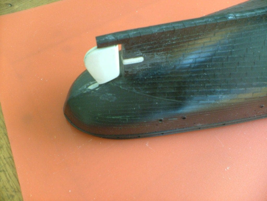
Bow area: Turning our attention to the this area and it was clear that massive alterations would be needed. USS Kearsarge had a very elegant prow which was reproduced in the kit, but this is absent in Harriet Lane. I started by cutting the bowsprit support and parts of the stem away and then making a horizontal cut at the level of the deck. This allowed the gunwales to be bent into a new stem made from styrene sheet which was spliced into the existing stem.
This obviously left massive holes where I had removed the supports. Thin styrene sheet was carefully cut and profiled to fill these spaces and glued in place. Polystyrene putty filler was used to blend with the original hull and when set the planking was reproduced by scoring with a sharp scribe. I have to say that the result was better than I had hoped for.
On close inspection of the available prints I came to the conclusion that the gunwales were too high for such a small ship. Out came the saw and the top section of the bulwarks were removed and the edges and ends smoothed. I also used the original gunport covers to fill in the open gunports and their surface was then textured to represent hull planking.
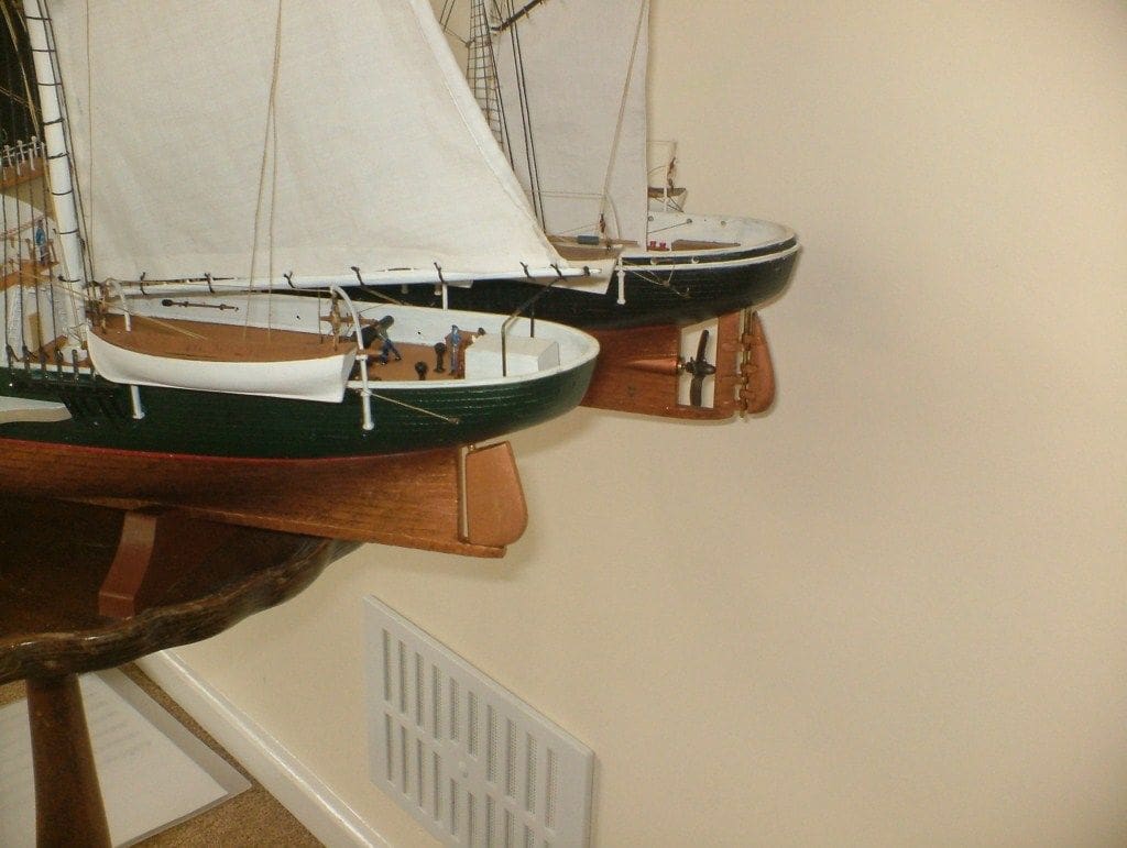
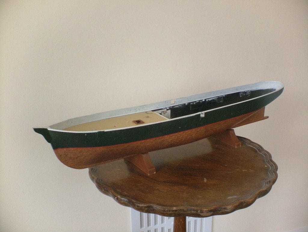
A considerable time and effort was then spent finishing the surfaces etc. I decided to paint the hull at this stage, for no reason other than to see what it actually would look like. From the limited information available it would appear that the hull was painted dark green and sheathed in copper from stem to stern below the waterline.
Below the waterline was painted with Humbrol copper enamel and above with Tamiya’s IJN green. This turned out particularly well as the black of the hull showed through which toned it down nicely. The waterline was demarcated with a red line and the gunwales insides and top rail painted white. The overall effect was quite fetching, so much so I then had difficulty working on it as I seemed to spend most of my time gawking at it!
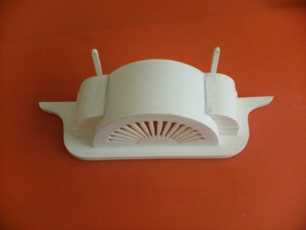
Paddle boxes
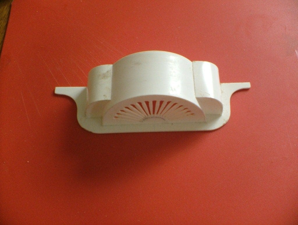
These were next on the list. I had decided on 3 1/4ins diameter for the paddle wheels. This looked about right and I had some convenient 3 1/8ins diameter copper tube that I could use as a former. The exact design of the boxes was difficult to ascertain as virtually every model and drawing showed a different layout. There were some common features such as the sunburst cutouts and the additional storage spaces.
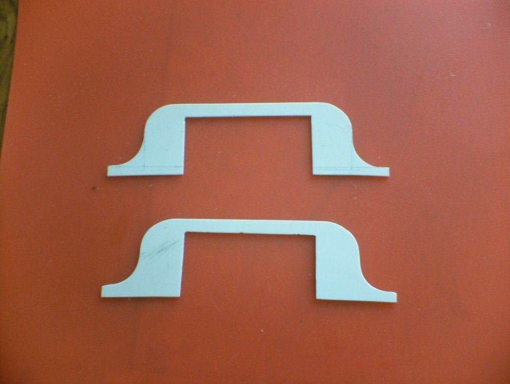
I fabricated the boxes out of styrene sheet, starting with the base supports, which were carefully adapted to the contours of the hull. The ornamental side sheets were trepanned and the cutouts formed by sawing and filing. This was a difficult procedure as the supports were thin and distorted very easily.
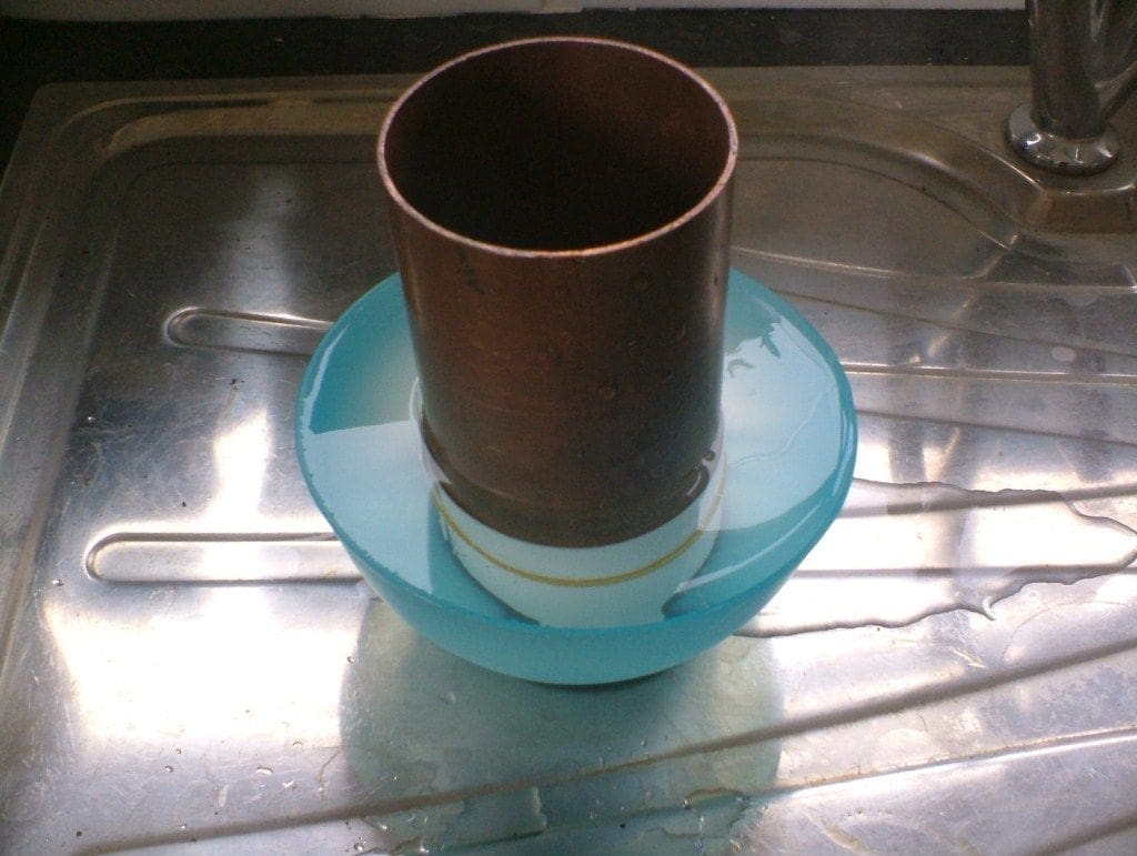
The tops were formed from thin sheet. The curve for these was achieved by wrapping a strip of styrene around the previously mentioned copper tube and held in place with elastic bands. This was immersed in boiling water and after ten minutes or so removed and cooled naturally. The strip then retained the curvature very satisfactorily.
The inner wall of the boxes extends down into the hull, so holding the boxes in place. Support brackets were fabricated from parts in the original kit, originally intended as anchor supports, but were just the right shape for these. They were cemented to the hull sides and the boxes merely rest on them.
Thin valance strips were cemented along the edge of the support and various embellishments were added to improve the appearance. The chain supports were cemented to the sponsons rather than the deck as it would make deck removal very awkward. The chain anchor points are hidden beneath some nice mouldings that were in the kit, but for what purpose I had no idea!
These were actually a bit of a nuisance as stretching across the deck between the funnel supports, they prevent the paddle boxes from being removed. In order to make the boxes removable the chains are permanently fixed at one end but made removable at the other end. The paddle boxes were then filled and filed as necessary and finally painted a buff colour. Using my Tamiya buff paint the end result was a little unexpected as it was more of a greenish colour than buff. A little bit of head scratching followed until my gaze happened upon HMCS Snowberry. The dazzle camouflage included a pale green colour, not unlike the one I had just applied. The penny then dropped as I must have used the bottle to mix the colour for Snowberry! No matter, as it was a greenish colour it blended in quite well with the hull anyway.
Letraset was used for the name lettering. I would have liked something a little more extravagant, but this was all the shop had available. I placed them on the paddle box sides, although there is no direct evidence that this is where they were, although as a rule most paddle steamers seem to have them there.
As they are a nice tight fit over the hull I will probably not cement them permanently until Harriet Lane’s sailing days are over.
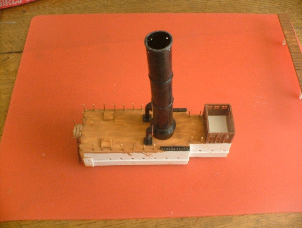
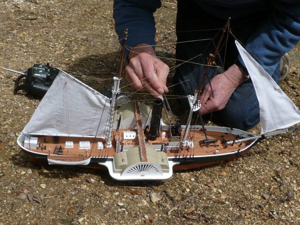
Superstructure
As with the rest of Harriet Lane, the design of the superstructure was very much a compromise. Some views showed a walkway between the sponsons. I started by cutting out the top deck profile from 2mm plastic sheet. The sides were then built up using 1mm sheet. The bridge was adapted from the existing (eventually it will contain the switch gear) deckhouse from the USS Kearsarge kit. The size seemed just about right and it was made from spare panelling. The windows were then glazed with clear sheet.
The air vents were from the original kit, but the skylight and companionway were built up from plastic sheet.
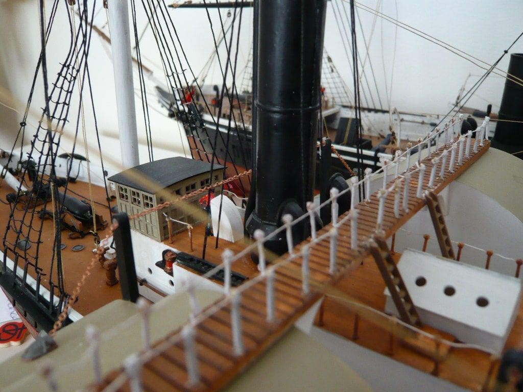
I was particularly pleased with the funnel. Harriet Lane’s funnel is almost twice as tall as Kearsarge’s, so I decided to utilise the original base, but construct a new funnel.
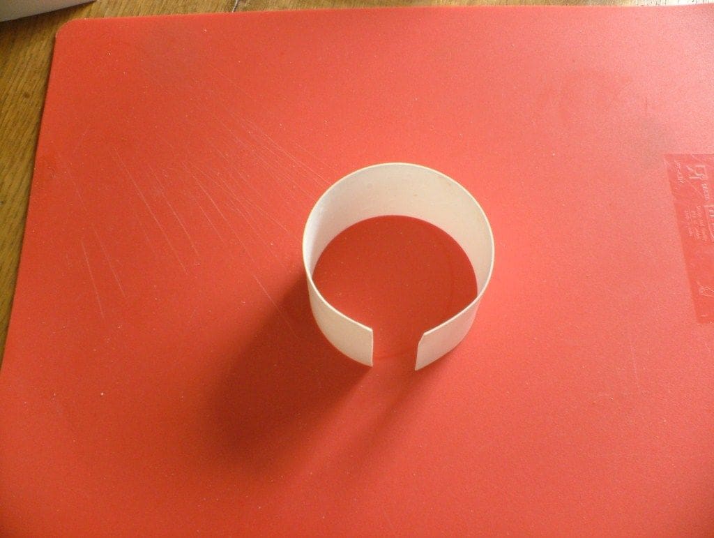
A length of thin plastic sheet was rolled to the approximate diameter required, allowing a good overlap of the edges. It was then slipped inside a length of 22mm copper tube and the whole thing placed in boiling water. The natural tendency is for the sheet to unravel and press against the inside of the tube. Once removed from the boiling water and allowed to cool, a very nice (almost) round tube was withdrawn from the copper former. The edges were trimmed to allow for about a 3mm overlap and then cemented together. The thickness of that resulting seam was subsequently thinned to produce a more realistic result. The chances are that the original funnel would have possessed riveted seams, so this would be quite contemporary.
The funnel banding was produced by cementing thin strips of polystyrene in the correct position. After sanding and painting, the result (although I say it myself) was very good! All that remained was to cement it to the base at the requisite angle. Holes for bracing wires were drilled near the top and thick thread used for the wires themselves. A new fitting for the safety valve exhaust was made to account for the increased height of the funnel. This was made by grafting the top moulded fitting to brass tube of the requisite diameter which was bent and attached to the funnel.
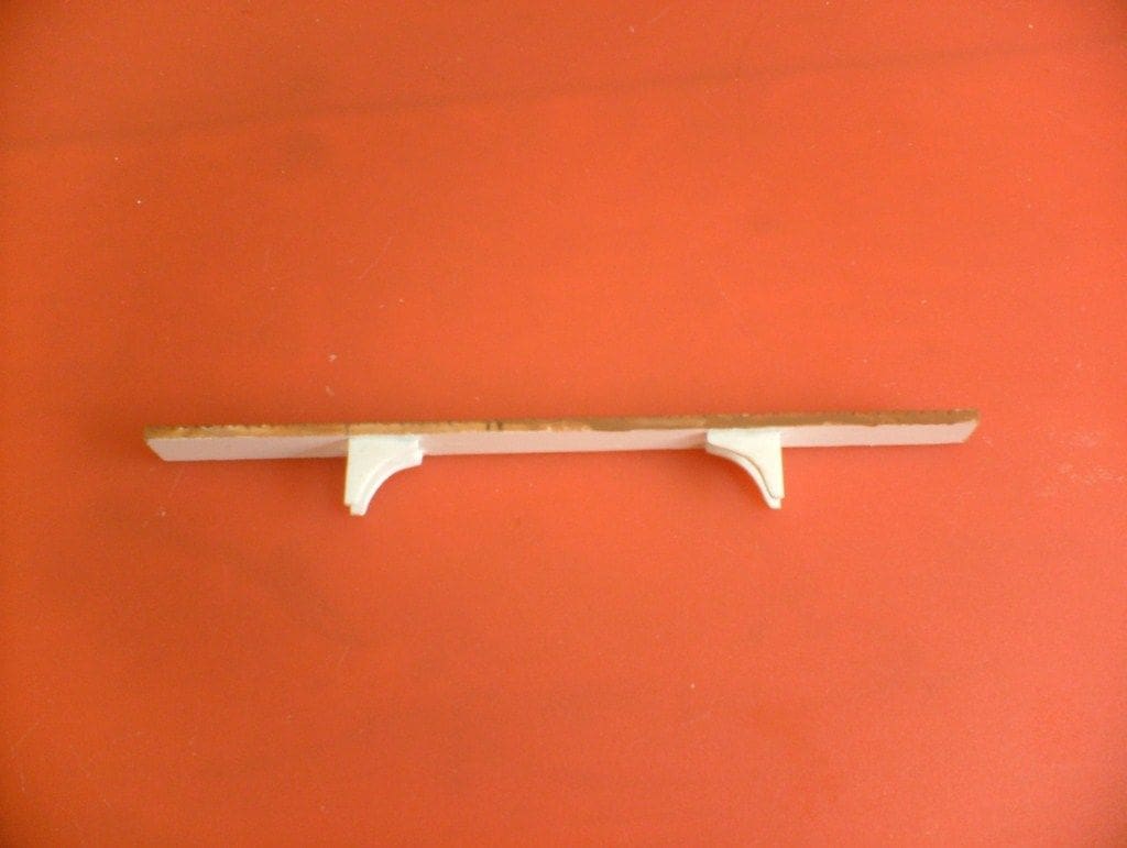
The aft steps were made from the original mouldings. They were, however, too short so I had to splice two together, but the result was acceptable.
I decided to construct a walkway between the two sponsons, which would not only function as a walkway but would also act as a bracing structure keeping the sponsons upright. The basic structure for this walkway was cut out from 3mm plastic strip and brackets were cemented to its underneath to act as bracing supports. The slatted wood effect was achieved by cross cutting with a fine saw. The railings were stanchions from the kit as were the steps. Once again these were a little short so a small platform was constructed to increase the span.
Fittings
Items such as the rigging anchor blocks, belaying pins and ram rods were adapted from the original kit and fitted where appropriate. Most pictures of Harriet Lane show two lifeboats, but one clearly shows four, so what to do? I went for the majority and fitted just two. These were taken directly from the kit as were their davits and oars.
One interesting point was the navigation lights. USS Kearsarge had them fitted on the raised foredeck which is not possible on Harriet Lane so they were modified and fitted to the sides of the deckhouse. It seemed probable that such a position would have been used.
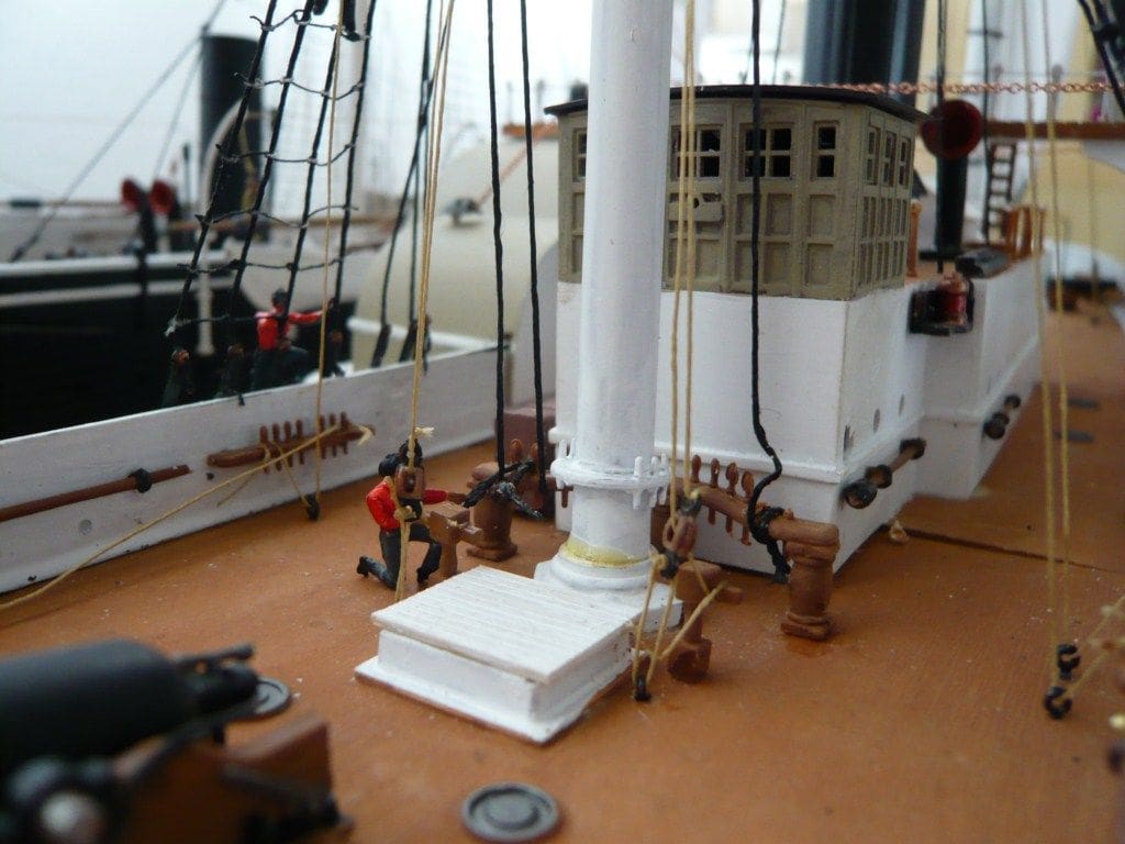
Harriet Lane seemed to possess a deck mounted windlass or capstan, call it what you want. The body of this was made from a modified gun carriage and the pulleys turned from brass. The anchor ropes were wound around them and then over the side attached to the anchors. The other ends were hidden in nicely formed mouldings of the same type that covers the ends of the paddle box chains.
Masts and rigging
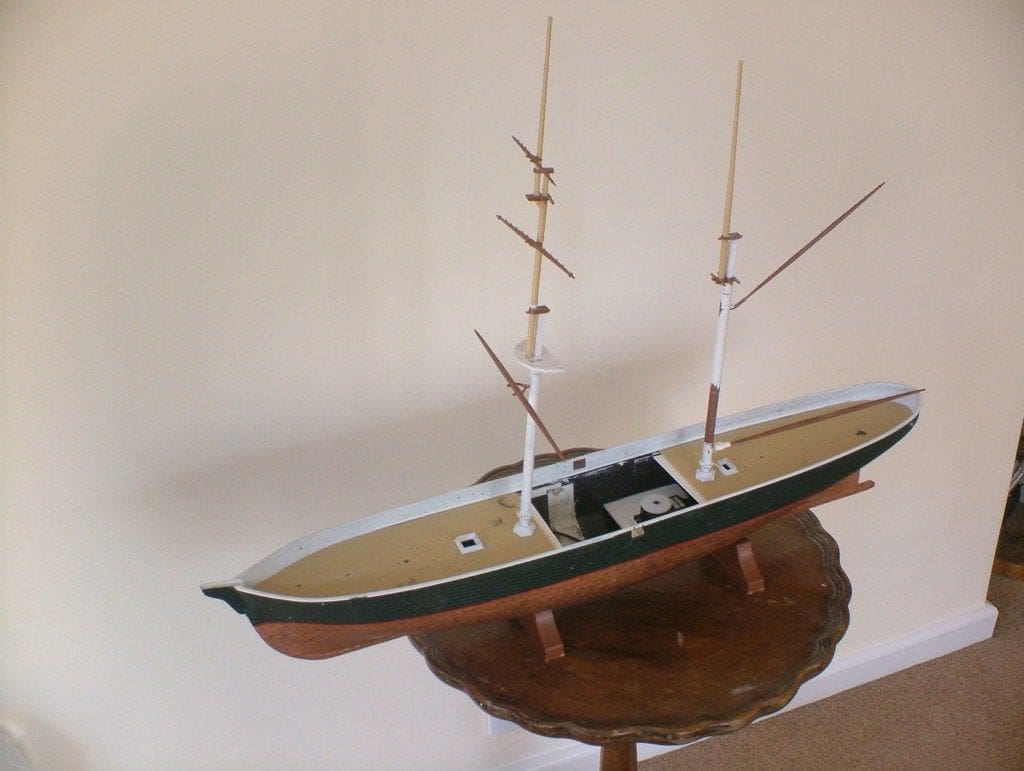
The next major difference between the two ships was the masts; namely Harriet Lane had two rather than three, a rather noticeable variation. So, the foremast was adapted to become the main mast and moved further aft. A hole in the deck was drilled to accommodate the new position.
The relative position of the main spars was also different. The mid-spar was moved higher up the mast by filling in the fixing slot and cutting a new one. The mizzen mast was different as well. The sail was much larger in Harriet Lane and placed much further forward and the mast importantly had to be made taller to accommodate the larger sail.
Rummaging around the box of kit parts I came across a nice cylindrical piece of plastic sprue that was just the job as it was the exact diameter of the mast and just the right length. The mizzen mast was cut in half and the ends dressed and drilled 1/16ins. The central section was drilled for a 1/16in brass rod that protruded about 1/2in from each end. This extension piece was then superglued in place and with judicious filling and sanding (as Ernie Wise used to say) you cannot see the join!
Booms
USS Kearsarge only had an upper boom. Once again looking to the kit for inspiration I came across the redundant main and middle spars that were just the job. All that was necessary was to remove the fittings and fit a pivot which was easier said than done.
The lower boom was treated as follows. First, a new male pivot was made comprising a length of brass rod bent into a right angle and fitted in a corresponding hole in the mast. A corresponding female pivot was made from styrene sheet drilled to match the end of the boom and cemented in place. The end result was quite satisfying.
The upper boom was treated slightly differently. The female hinge from one of the kit booms was cut off and drilled to suit the boom end and cemented in place. This hinge was already at a suitable angle so the boom was automatically positioned correctly.
Bowsprit
This needed some attention. I used the original, but if I had used the existing fittings it would have been at too steep an angle. The fixing end of the bowsprit was chamfered further and a notch filed in the stem that allowed the bowsprit to lie lower and at a much shallower angle whereby it looked much better.
It is held in place with cord bound around the bowsprit and through a slot cut in the support. When completed this gives the impression of thick rope.
Rigging
Before dealing with the power plant and paddle wheels I attacked the rigging, I really did not fancy making the paddle wheels at all and put it off for as long as possible. I basically copied Kearsarge as the fore and mizzen mast are almost exactly the same. However, I made some alterations as indicated by some of the drawings and lithographs, but a note of caution here as these drawings and etchings are notoriously inaccurate and should not be relied upon for precise information, but can give a good overall perspective idea.
The aft rigging anchor blocks were fitted permanently, but the foremost were made removable as this was necessary to allow the removal of the paddle boxes. If all were permanently fitted, then the paddle boxes would be locked permanently in place.
One item on USS Kearsarge I was never happy with, were the ratlines as they just did not seem to fit at all very well. So, for Harriet Lane I made individual ratlines with black cord. They were anchored at one end by drilling a hole through the rigging block and supergluing that end in place. The line was then run up and around the mast to the other block.
The ratline steps were made by knotting thinner cord. In surgical terms they were attached with ‘continuous interrupted sutures’ which is a bit of mouthful, but the overall effect was a vast improvement on my previous efforts.
Paddle wheels
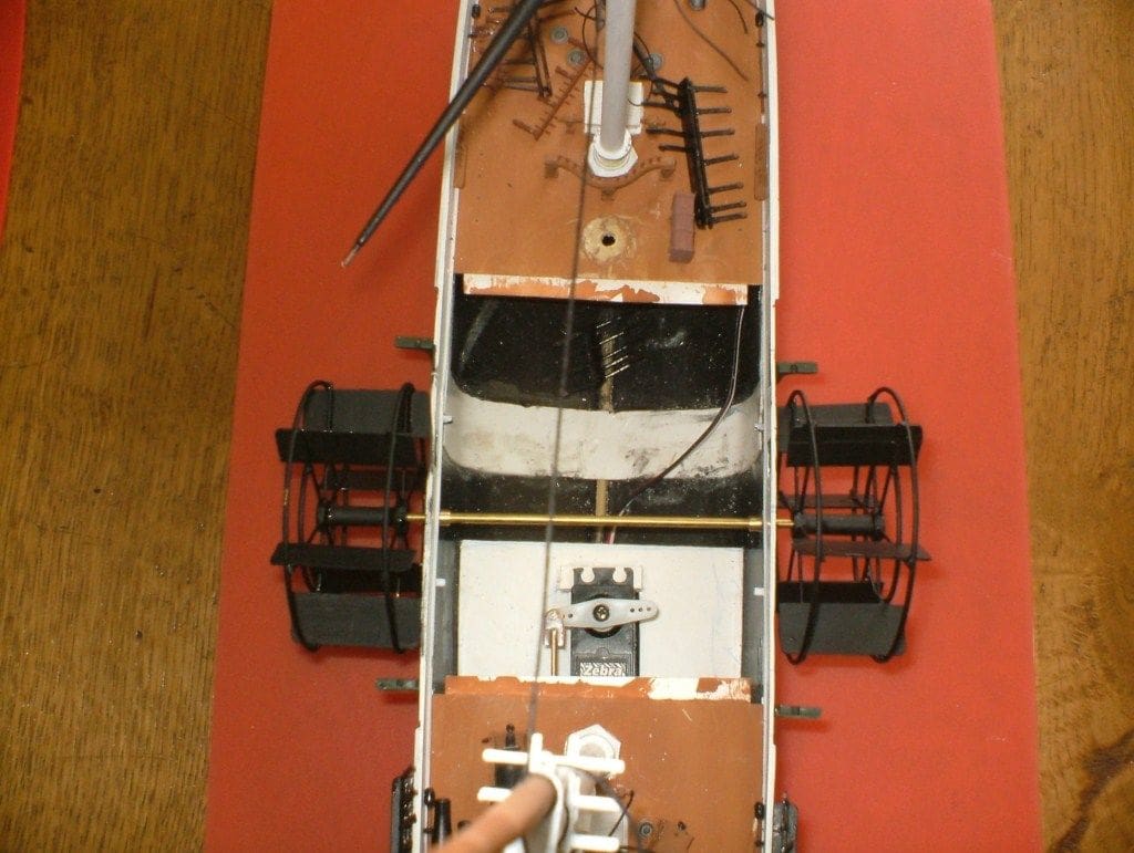
It was now time to tackle the really difficult part, namely the paddle wheels. I started by drilling 3/16in holes in the side of the hull to take the main bearings. I should have done this before making the sponsons and fitted them around the holed rather than the way I did it, but we live and learn!
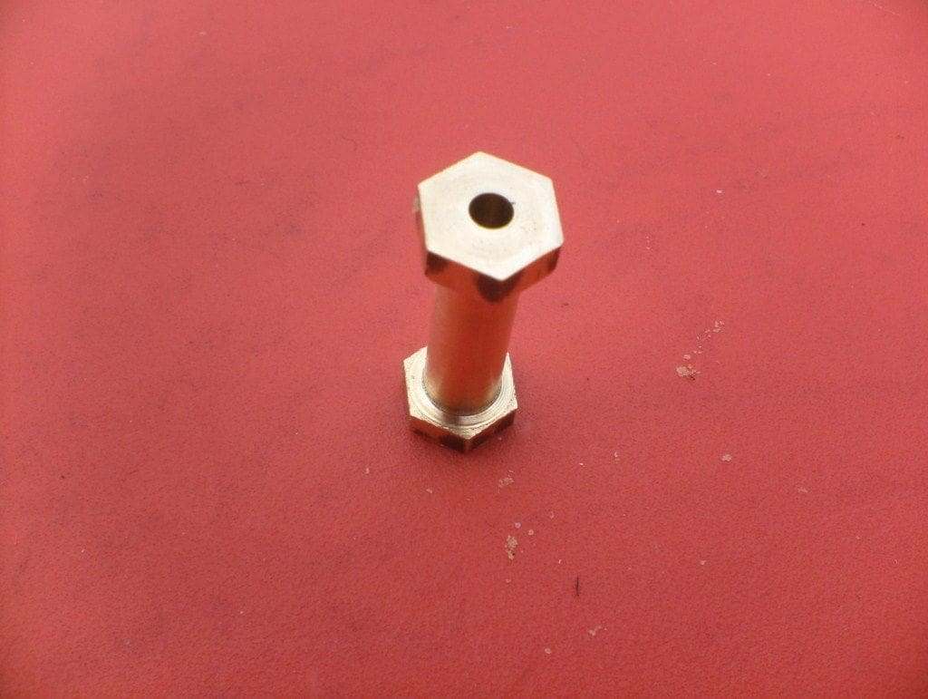
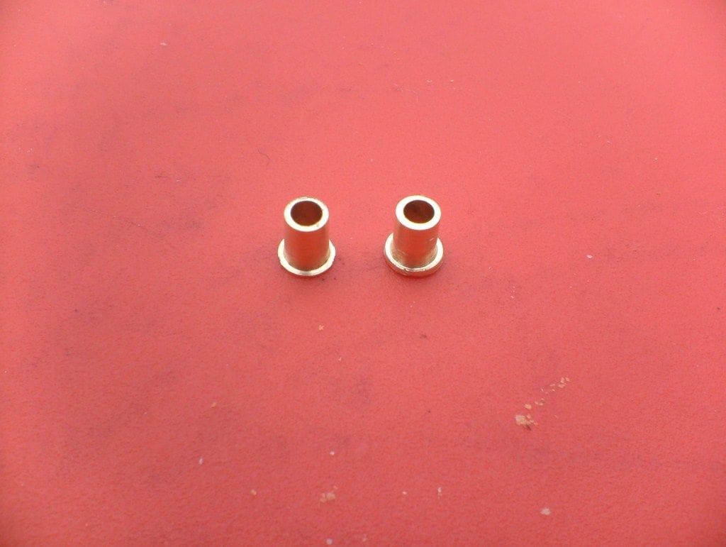
The bearings were machined from brass rod to a nice fit in the hull and drilled 1/8in for the main paddle shaft. When fitting the bearings into the hull the shaft was inserted to ensure that they were in perfect alignment, but do make sure that no glue penetrates though to the bearing surfaces. Next on the list were the paddle hubs.
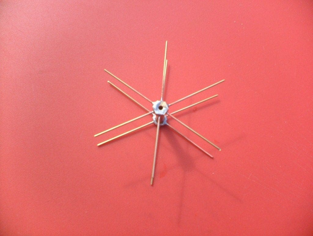
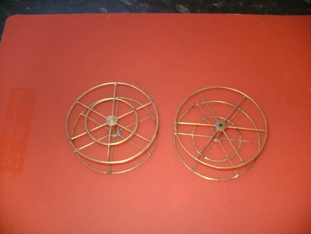
For these I used 3/8in brass hexagonal rod as I like using hexagon as it is easier to cross drill than round bar for obvious reasons. This rod was machined to a length of 1 1/4ins with the central section reduced in diameter to about 1/4in. As the name suggests, a hexagon bar has six sides and I would have liked a few more paddles, but in the end decided to just have six per hub for practical reasons. Each flat was centrally drilled 3/64in for a brass radial arm that would support a paddle. Next, the brass paddle wheel rims had to be constructed and this is where copper tube comes into its own.
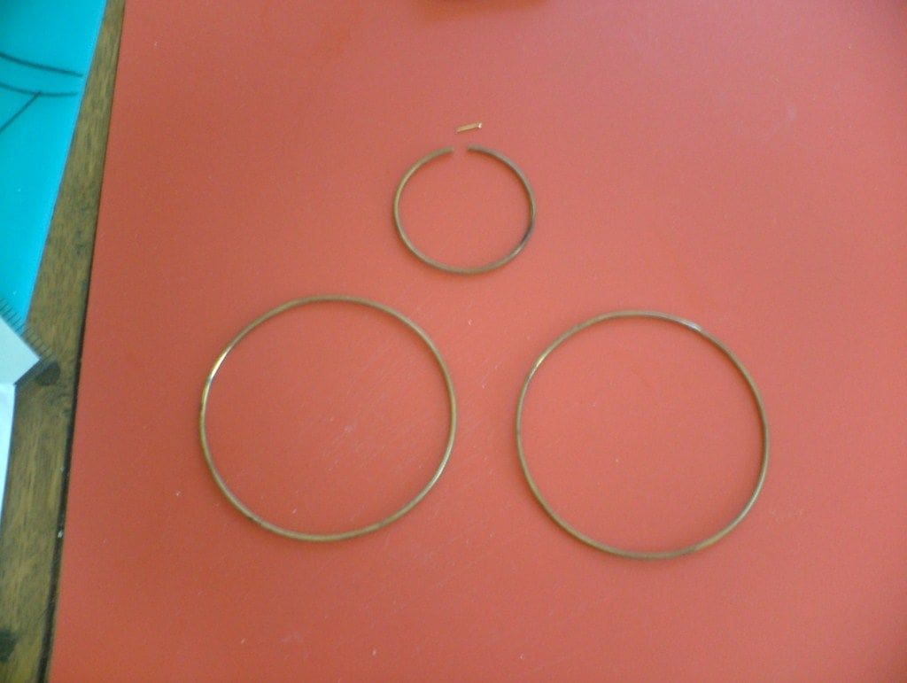
The first task was to soften lengths of 1/16in brass tube by heating to redness and then quenching in water. The next step was to wrap this around the 3 1/8ins copper former tube and trim until the ends met. A small length of 1/32in brass rod was then bent to the correct curvature and used to locate inside the cut ends and that joint was soft soldered. This produced a rim with an inside diameter of approx. 3 1/8ins.
Four of these outer rims were needed plus two smaller rims of 1 1/4ins diameter, also made in much the same way. I only used these smaller rims on the outer face for convenience, but there is nothing to stop you from putting them on both sides if you wish.
The hub and radial arms were then carefully soft soldered to the inner and outer rims; a tricky procedure but not impossible. Once all was soldered, the wheels were checked to ensure that they would rotate with at least a reasonable degree of truth and adjusted as necessary. So, a bit like the ‘Generation Game’ – that’s all there is to it! But seriously, with patience, round nicely rotating wheels can be made this way relatively easily. It now only remained to make the paddles themselves.
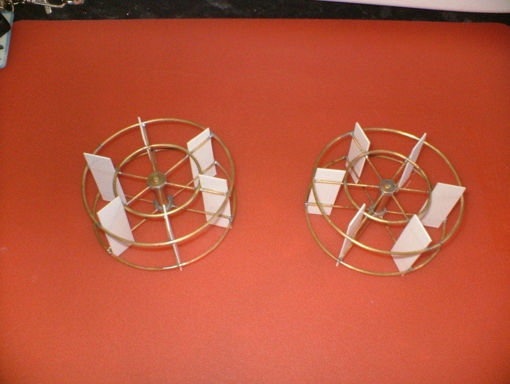
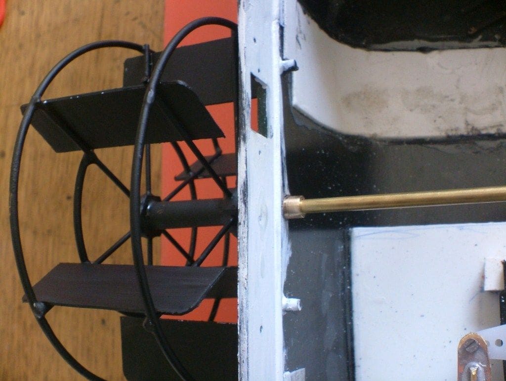
These were simple non-feathering paddles made from styrene sheet glued to the radial arms with small support brackets on the trailing faces, but do remember that right and left handed wheels are needed. After cleaning and tidying-up, the wheels were painted matt black.
They slip over the main drive shaft and can be either permanently attached with superglue (not recommended) or better, secured by a small grub screw though the hub.
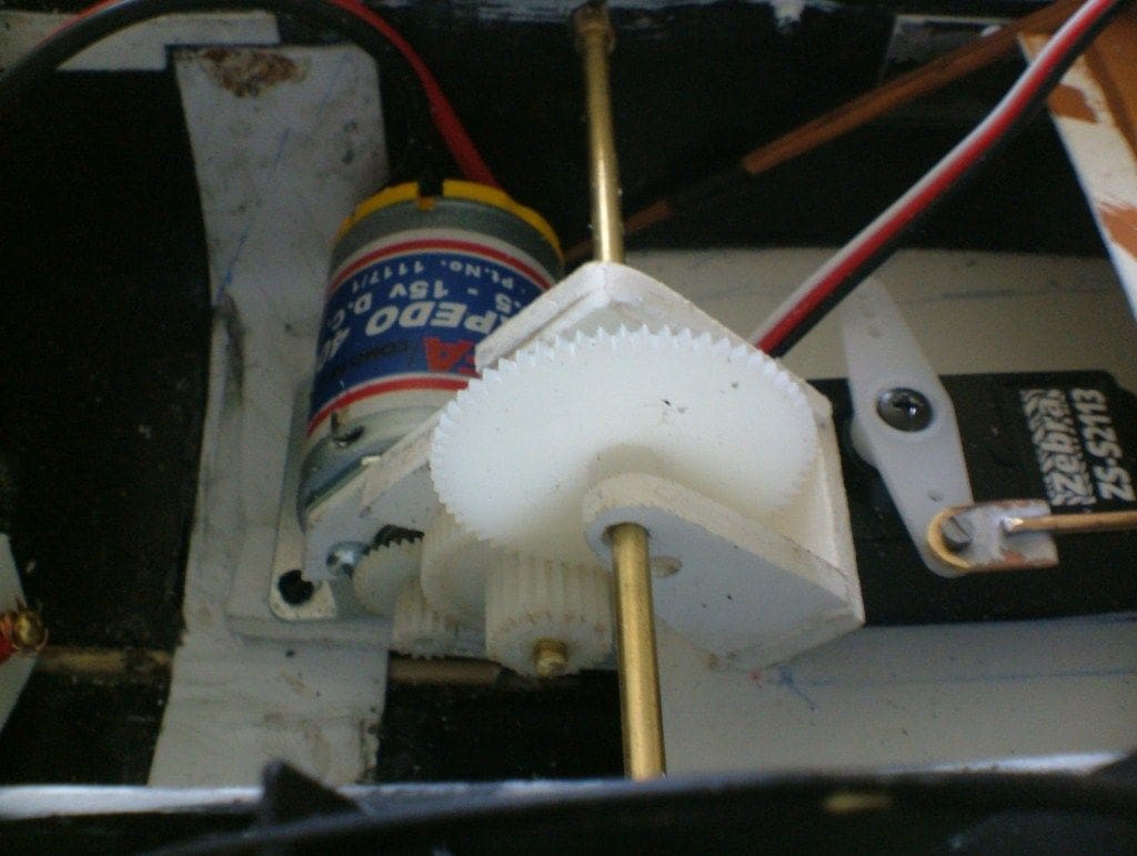
Motor and gearing
This was next on the list and I used a standard MFA Torpedo 400 motor running off a 9v battery. The motor is connected to the main drive shaft by a simple gear train for which I used gears from a replacement gear pack for a large heavy-duty Futaba servo. If you use these or similar, you will have to choose the ones to use very carefully as not all of them are designed to mesh together. I used three gears to reduce the speed; more would have been better, but they were the only ones that I could get to mesh.
A gearbox frame was made from thick styrene sheet and screwed to the motor mount and an auxiliary mount was made to support the final drive gear on the main shaft. This gearbox was screwed as well as being glued together for extra strength and the whole thing is screwed to a platform attached to the hull. The motor is offset to one side of the beam thus necessitating the inclusion of compensating ballast.
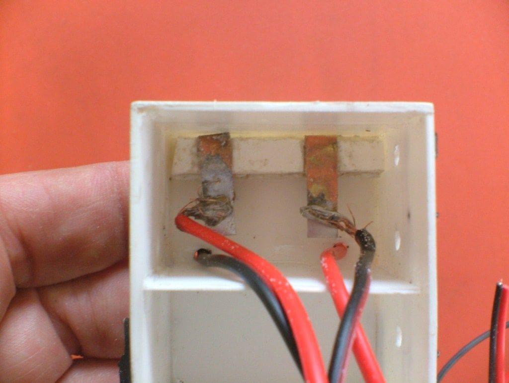
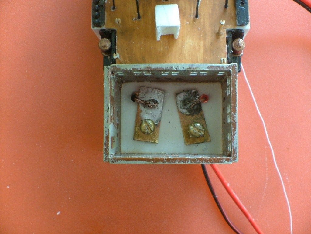
On/off switches
It was now time to construct the two on/off switches by using the simple expedient of a spring loaded screw that I had used successfully on my last few projects. These fit inside the main deckhouse and are accessible by simply removing the roof and turning the switches (screws) with a small screwdriver. Simplicity itself, provided of course you remember to take the small screwdriver to the pondside!
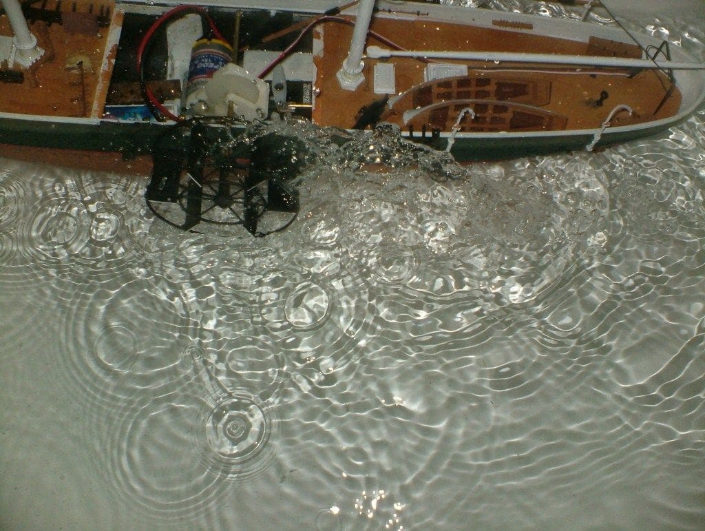
Bath tests
First tests in the bath were quite encouraging. The paddle wheels turned reasonably truthfully and I was surprised at the amount of water churned up. So much so that it started to enter the hull, but hopefully once the paddle-boxes were fitted this would be deflected back into the water. This did confirm my suspicion that it is vitally important to keep the area around the paddle boxes as watertight as is possible.
Now the end was in sight. A lot of small items needed to be constructed such as the cannons, their ram rods and the suchlike, but these were all straightforward. I did decide to fit a couple of sails, the big one at the back and a triangular pointy one at the bowsprit. Like USS Kearsarge, they were cut out of an old cotton shirt and attached with rigging thread, overall creating quite a quite nice effect.

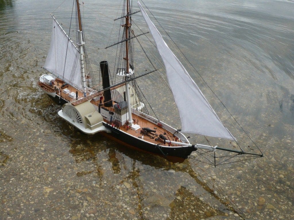
Sea trials
These were quite an adventure. The day was somewhat overcast with the occasional light gust of wind that to the model would be like a storm! Harriet Lane settled nicely in the water, the trim was about right, but immediately I realised that getting the trim was vitally important, otherwise it heeled over alarmingly when a gust of wind caught her.
The paddles worked almost too well, producing a fine wake but also forcing water out of the paddle wheel cutouts onto the paddle box base. The 9v battery was adequate and she had a good turn of speed. Working with paddle wheel models is very exacting and far more so than screw equivalents, but also very rewarding.
Conclusion
To improve the sailing characteristics and waterproofing of the model, if you are interested in following my example, I would recommend backing the paddle box cut-outs with styrene sheet, painted black. This will prevent the ingress of water and yet the model will still look right.
Nine volts was a little too much power and probably six volts will be adequate and I would, if I were doing this again, reduce the size of the paddle blades to lessen the water turbulence and reduce the speed.
All in all though, this was a successful conversion producing a very handsome model and a bit different from the others we regularly see at the pondside.


