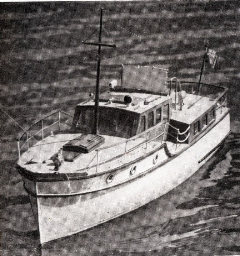
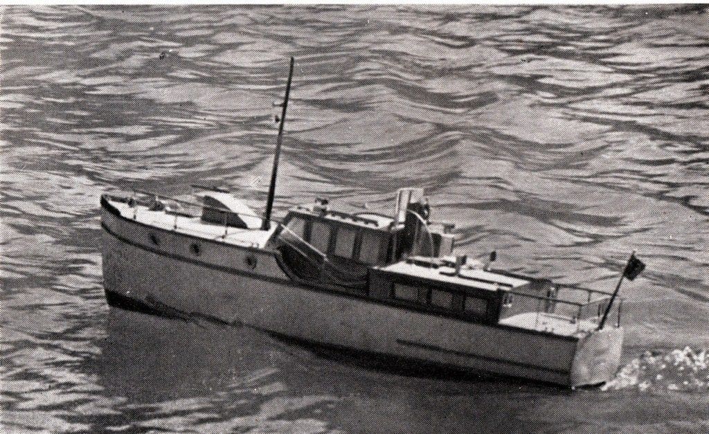
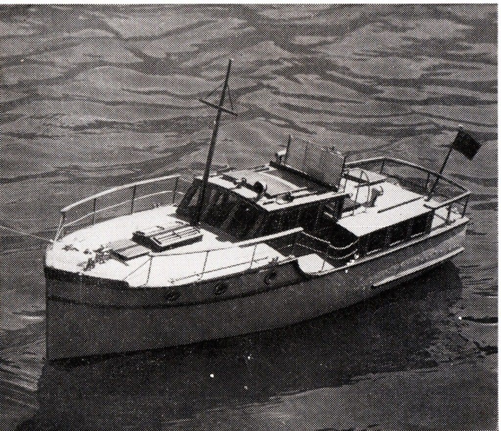
A revival of a classic river cruiser design, length 28.5 inches, presented by COLIN BISHOP
Visit any marina and 99.9% of the boats you will see are made of plastic! The introduction of glass fibre and resin construction (GRP) for recreational craft in the mid-1960’s transformed the boatbuilding process and these days virtually all leisure craft hulls are moulded rather than built from components. So robust was the new material that most of the boats constructed over the last 40 years or so are still around, much to the chagrin of modern boatyards who are having to compete with second hand bargains which can be readily renovated!
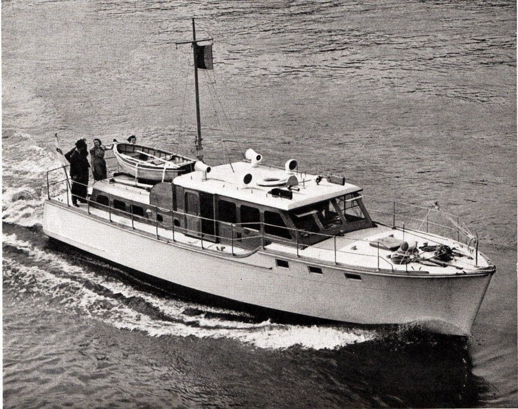
Before GRP it was a different story of course with most boats being built of wood in the traditional plank on frame manner with the exception of some larger ones constructed of steel. The immediate postwar period saw the appearance of some very attractive designs for the ‘gentleman sailor’ and the river cruiser Dubarry, built by the famous firm of Thornycroft was one of these. The design of this craft was adapted for model makers by Mr M. C. Cowell and published in The Model Boat Book, 1950, compiled by Geoffrey Deason who was one of the two original joint editors of Model Maker magazine. The plans were subsequently published by Model Maker, the predecessor of Model Boats.
Enjoy more Model Boats Magazine reading in the monthly magazine.
Click here to subscribe & save.
Through the good offices of our regular contributor David Wiggins who located copies of the original plans, they have once more seen the light of day and are now available through the MyHobbyStore Plans Service, MM2063.
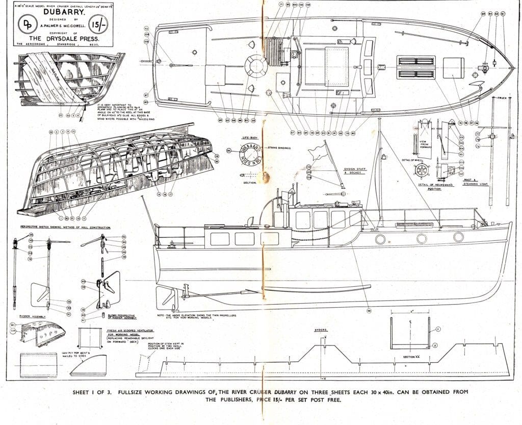
The plans comprise five sheets. The first is a general arrangement drawing of the full size vessel at 1/2 inch to the foot by Messrs Thornycroft, which includes an isometric view of the planking and rib arrangements. The model maker’s drawings, which are also well detailed, come on the next two sheets at 3/4 inch to the foot scale giving a model length of 28.5 ins. (72.4cm) with a beam of 7 7/8 ins. (20cm). These drawings show all the external detail, frames and include comprehensive constructional information together with perspective drawings of key elements of the model. The fourth sheet shows the full size interior arrangements for those who wish to include such detail. The fifth sheet has a comprehensive list of the numbered dimensioned parts as referred to in the text. Optical Character Recognition software (OCR) has also enabled the original building instructions to be readily recovered and these are reproduced later in this article with the addition of metric equivalent dimensions. The instructions are pretty much self-explanatory, but do rely upon some building techniques which have moved on since 1950, so I have taken the liberty of prefacing the building text with some relevant updating.
Dubarry would make a fine true scale project for anyone interested in these classic vessels and who likes to work in wood. Construction is quite straightforward and should present no problems for the builder with some experience whilst even a novice with woodworking skills should be able to do the boat justice with a little care and attention. Wood is a very forgiving material and minor mistakes can be readily corrected which is not always the case when working with more ‘modern’ materials. Anyway, here though are some things to bear in mind!
Power
The plans envisage a single screw model version using a small diesel engine, although the original vessel was twin screw as is also shown on the plan. There is no reason why an i.c. engine could not be fitted, but this might limit the water facilities where the model could be used. A single electric motor could be substituted and this would not need to be very powerful as Dubarry had a displacement hull with a modest speed of around six knots. This is emphatically not a planing boat, so think sedate, dignified and classy!
Those builders opting for the authenticity of twin screws will notice that the propellers shown on the plan are very small. The original vessel was fitted with Thornycroft DB2 petrol/paraffin engines with reducing and reversing gear. The model could be fitted with small screws and high rpm electric motors but I would suggest that slightly larger propellers and low drain 545 type motors would give a better and more sustained performance. So, if fitting twin shafts, allow clearance for some experimentation in propeller diameters.
If going for the twin screw option you would need to think about the single rudder configuration which might result in an overly large turning circle. I would be inclined to fit a mixer such as the ACTion P94, reviewed in the September 2010 issue of Model Boats, which should improve the handling considerably.
Materials
The majority of this model is constructed from plywood and common modelling stripwood (spruce) so there should be no difficulty in obtaining suitable material. The reference to ‘Deal’ wood relates to varieties of the common northern pine wood used to make general joinery in the 1950’s and 1960’s. The superstructure is specified as being varnished, so it may be worth giving some thought to using an alternative wood or even veneer which will take a more realistic finish than bare plywood on a model of this size.
Hammer and nails
Model building techniques in the postwar period frequently featured nailing components together as the instructions demonstrate. The use of modern woodworking glues such as Aliphatic Resin and epoxy adhesive means that there should be little need for mechanical fastenings, just a bit of initial pinning and clamping while the adhesive sets.
Filling
Reference is made to ‘paint filler’ to fill in unwanted gaps. Any modern model filler could be substituted as long as it is not harder when set than the surrounding woodwork. I have found Ronseal Wood Filler to be an excellent choice in this sort of situation as it sands down very easily indeed and blends in with the surrounding wood.
Fitting the running gear
The references to using red hot steel rods to open up the propeller tube apertures bring back vivid and choking memories! These days we just drill the holes slightly oversize and rely upon epoxy resin and car body filler to position and firmly fix propeller and rudder tubes in place. The vast range of reasonably priced propeller tubes and shafts on the market make them the obvious choice to use while there is an option to either make your own rudder arrangement or to adapt a suitably sized commercial unit.
Fittings
The text assumes that builders will make their own fittings and many builders will do so. However there is now a wide selection of commercial fittings on the market, some of which will be suitable for Dubarry.
In general
It should be fairly obvious where modern techniques can be substituted for those used in 1950, so the instructions should be read with this in mind and amended as appropriate. The basic constructional methods will remain essentially the same however.
Imperial to Metric conversions.
I have inserted the metric equivalents of imperial measurements within the text but as a quick reference the approximate conversions for practical purposes are:
1/64 in. = 0.4mm
1/32 in. = 0.75mm
1/16 in. = 1.5mm
1/8 in. = 3mm
1/4 in. = 6mm
1/2 in. = 12.5mm
And so, without further ado, let us launch(!) into the original building instructions. These are printed here virtually identical to their original presentation.
The River Cruiser Dubarry
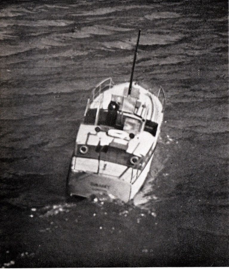
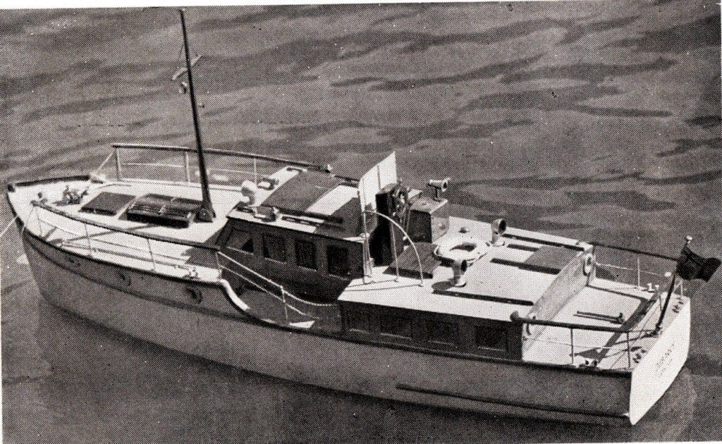
The model river cruiser Dubarry is more advanced than any of the examples so far described, and if correctly built and finished with care and patience, can fairly be classed as a first rate exhibition piece in addition to being a fine seaworthy little craft, suitable for sailing in regattas and steering competitions with excellent chances of success. Dubarry is a scaled-down replica of a 38 foot boat built by Thornycroft, and if built as a working model, she differs from the prototype mainly by having a single propeller instead of the twin screws of the original.
Although ranking as a first-class model, the comparative beginner need feel no diffidence about tackling this job, provided that he is prepared to follow the drawings and building instructions closely and carefully, and to devote a considerable amount of his leisure time to its construction. A job of this nature cannot be hurried, and in fact at least as much pleasure and satisfaction may be obtained from the building of Dubarry as from sailing her.
Assuming that a commercially made engine is to be used, the prototype model is very adequately powered with a 1.3 c.c. Mills diesel, a lathe is not essential, although the use of one is very helpful in making small deck fittings which will take a longer time to shape by hand. The complete cruiser can be built to a really good standard using only the normal handworking tools usually possessed by the amateur craftsman.
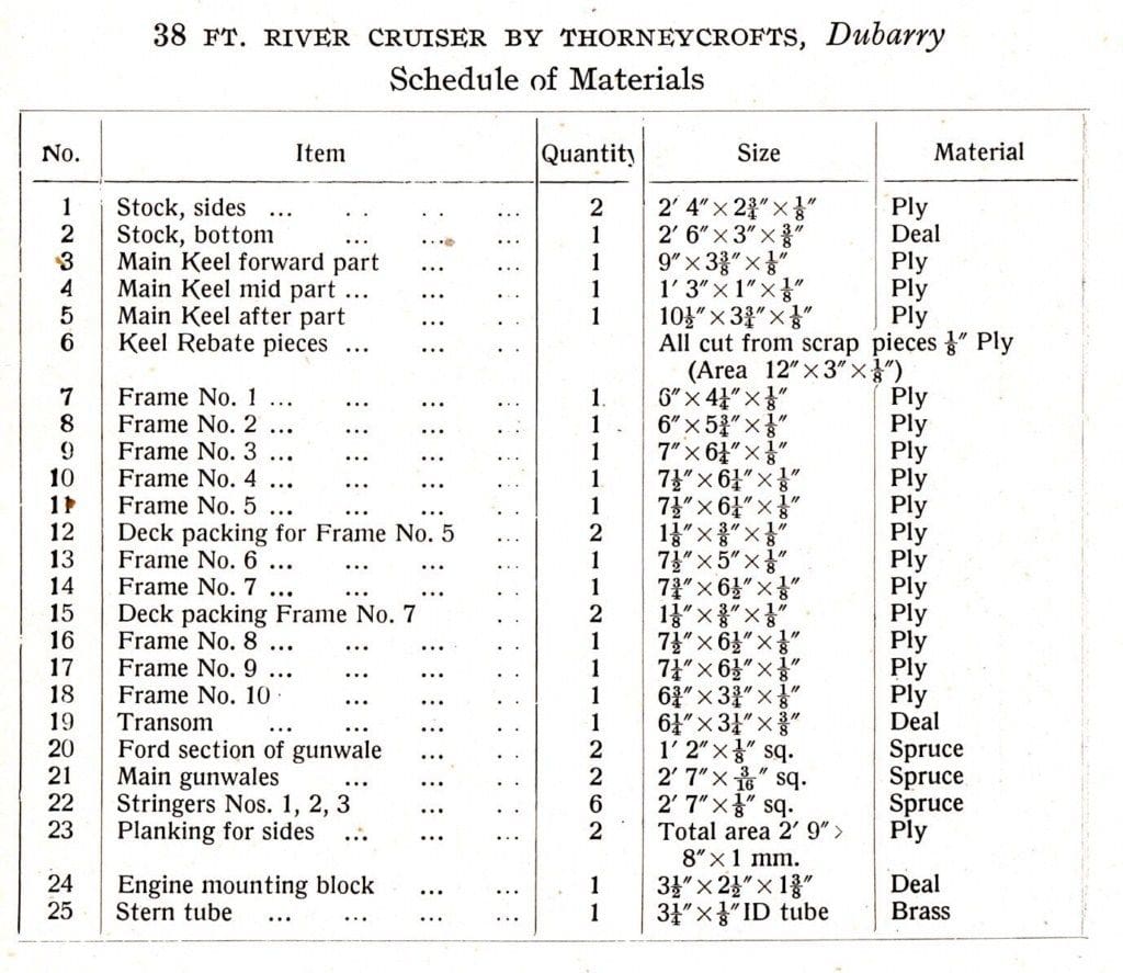
Before commencing the work, read through the schedule of materials given at the end of the chapter (now printed on Sheet 5 of the plans), and either procure the right materials or ensure that they are readily available and will not hold up the work when once underway. As in other designs by Mr. Cowell, special stocks (building stand) form the basis on which the frame is built. These are made to the drawing out of plywood and Deal, and are worth constructing with care and accuracy, as the ultimate success of the hull depends on them.
Having built up the two side pieces and baseboard of the stocks, work can proceed with the keel. If you have sufficient 1/8 in. (3mm) plywood, cut out the centre piece of the keel (Items 3 to 5), in one piece. If not, scarf together three pieces as shown on the drawing, being very careful that the keel retains the correct shape. From some small pieces of scrap ply or pieces left over from the keel, cut out the small pieces which make up the false rebate to which the planking is seated. This is called a ‘ false rebate’ as in actual practice the main keel has a natural rebate cut into it, but this of course, makes a great deal of work. Glue these rebate pieces on to the keel as shown, and pin them with 3/16 in. (4.5mm) x 22g. brass brads every 3/4 in (approx 2cm), keeping the brads to the top edge. This is necessary, because the rebate has to be bevelled, and to do this either a chisel or a file will do very well. If the brads are not put in high up, the chisel will cut into them.
Cut out the frames and bulkheads, also from 1/8 in. (3mm) plywood, and cut in all the notches, or jogs as they are correctly called, to take the keel stringers, etc. The transom is more difficult, because it is on the bevel and is cambered across the stern and on the top edge. However, with care this can be accomplished, and the keel, bulkheads, frames and transom can then be assembled on the stocks.
Now fit the gunwales and the stringers into their respective jogs, being careful not to have any breaks as this will make an angular projection, and will interrupt the planking. It will be found that in a number of cases, mostly towards the forward end of the boat, the jogs will have to be cut deeper on one face of the frames than the other, because of the general contours of the hull and therefore, all stringers should be tried for fitment before they are finally fixed into position. When this has been accomplished, the hull can be planked. Cut out all the planks, to the template shapes given on the drawing, and begin by fitting No. 6 plank, being very careful to position it as shown in the perspective drawing. All the other planks will depend for their correct position largely on this point. Glue the edge of the plank where possible (this depends where it crosses the stringers) and also nail into as many points as possible, but definitely nailing into gunwales and keel rebate at about 3/8 in. (9mm) to 1/2 in. (12mm) spacing, with the 3/16 in. (4.5mm) x 22g. brass brads already described. Very soon the hull will begin to take shape and the planking will be completed, thus disposing of one of the most tedious of the operations. When the glue has become hard, the outside of the hull can be sandpapered, as it will be found that the planks cause ridges. If possible, apply some paint filler to the surface, and when hard rub down with a special paper known as ‘wet and dry’. This will leave a really smooth surface and the planking seams will then have become invisible.
Cut out the engine mounting block to shape, and secure it firmly in position, gluing it to the bottom of the hull and screwing it from the outside with four of 3/4 in. x 4g. brass c/sk. wood screws.
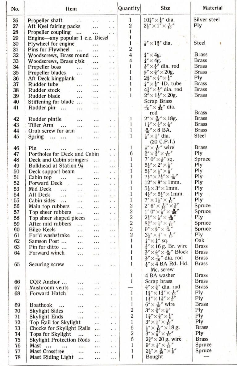
We now have to bore the stern tube hole and for this operation precision is called for, as any variation up or down will result in the mis-alignment of the engine and propeller shaft. For those who do not feel too confident it would pay to install the propeller shaft first and then, if there is any discrepancy in height, it can be adjusted in the making of the engine mounting block. But reverting to the making of the engine mounting block; the entry of a 1/8 in. (3mm) drill is assisted by the piece cut away from the keel. This should already have been done when the keel proper was originally cut out. When the 1/8 in. (3mm) drill has been put right through the hull, the hole can be opened up by using a red hot 3/16 in. (4.5mm) diameter steel rod; if the 1/8 in. (3mm) hole made by the drill was off centre, by bearing one way with the red hot bar any slight error can be corrected. Now insert the stern tube which should be a driving fit, as otherwise it may then turn with the shaft and fail to do its job as a bearing. Fit the packing pieces to the after end of the keel, making sure they are well glued. This will tend to assist in making the stern tube rigid. It is advisable to cramp these packings in position with a small toolmakers’ cramp whilst the glue hardens. Make up the propeller shaft and propeller to the drawing and try them with the engine for correct alignment. If this is satisfactory, remove them again as these can be installed at a moment’s notice when the model is complete.
Next fit the rudder bridge, or short king plank, which supports the rudder tube until the deck is fitted. Now comes the point of boring for the rudder tube. From the outside of the hull, drill a 3/16 in. (4.5mm) diameter hole through the keel. Insert the short piece of tube through which the rudder stock is to operate. This, like the stern tube, should be a driving fit. When this is in position, or before, solder to it a small washer which in turn has been drilled to take two small brads. This will prevent the tube from moving. Make up the rudder in brass in the manner shown on the perspective sketch and fit this in position. If the builder decides to have his rudder spring loaded, it means that to remove the propeller the engine must be lifted out, this is not as difficult as it sounds but is a minor operation. On the other hand, by having the rudder free, omitting the spring loading, the tiller arm can be removed and the rudder dropped out to change the propeller. The designer advises the spring loaded rudder as it is extremely convenient for running and obviates all patent deck gear to set the rudder in desired positions (obviously not necessary if the model is to be radio controlled).
Two items which must be fitted before the deck goes on are the after mid-rubbers and the bilge keels. Both are shaped, and when glued and nailed to the hull, require the nails riveted over on the inside. (It would be very inconvenient if these became loose when the model was finished.) Now paint the interior of the hull with two coats of oil-resisting paint.
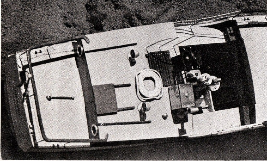
Assemble the after cabin end, together with the beam known as Station 9 1/2, fit the portholes and also the celluloid, and erect the whole to the hull at the correct position given on the arrangement drawing of the deck.
The decks can now be fitted. Firstly, fit the stringers into the jogs as shown on the drawing and cut the decking to shape. The forward deck can be split into three sections to economise in plywood, but if the builder has sufficient material it can be put on in one piece. To avoid various fittings being knocked off at a later date, it is a good idea to fit them before the deck goes on. The nails can then be riveted over underneath the deck.
Fit the deck; that is the forward section, the after sections, and also the two side mid-pieces. Carefully sandpaper round the edges, and fit the top rubber, making it a neat fit against the mid-section fairing pieces. Make up the cabin sides complete with their windows and celluloid. Erect them in position and glue and nail them. It will be found that one frame fouls a window. Cut this neatly away. As with the deck, most of the cabin top fittings can be completed and fitted, so that the nails can be clenched inside. Before finally fitting the top, remember to varnish or stain the inside of the cabin, and glue some small curtains to the windows.
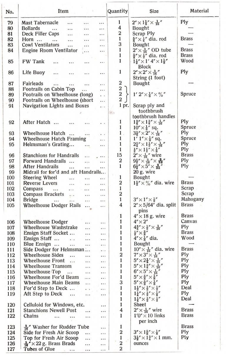
The wheelhouse is a separate unit and the exploded perspective gives a good idea how to assemble the various parts. In making up the sides, instead of using 1/8 in. (3mm) ply and gluing the celluloid inside, thin celluloid can be used and sandwiched between two thicknesses of 1/16 in. (1.5mm) ply. This is more trouble, but it makes for a neater job.
Make and secure the various fittings to the wheelhouse top. Cut out and fit the two steps to the dropped mid-deck with the wheelhouse between them, the ends of the wheelhouse resting on the forward deck and cabin top respectively. Note: For a working model, omit the compass fitted to the forward side of the helmsman’s control unit, as with this in position the wheelhouse will not be able to be lifted clear.
The skylight on the forward deck is very attractive, and quite easily made to the ‘broken down’ arrangement on the drawing. Care should be taken to make it an easy fit into the aperture. When running the boat, this skylight should be changed for the deck ventilator, which scoops in air to the diesel engine. For this purpose, it is advisable not to put celluloid into the rear windows of the wheelhouse, as when the boat is moving, the deck ventilator hatch and the open windows provide a through current of air essential to the small diesel engine installed.
The deck rails may present some difficulty, so a word as to their construction. A good idea to maintain them in a parallel line is to make a jig, which is easily done by cutting two pieces of Deal about 1 1/2 in. x 3/8 in. (38mm x 9mm) thick, with sawcuts corresponding to the uprights. These, when clamped together with the uprights in the sawcuts, will leave both ends exposed. On both top and bottom fit small washers or plates cut to size which should then be soldered in position. Cut the deck rail to shape and drill the holes for the uprights. Remove uprights from the jig and fit them to the rail. Cut off the protruding ends of the uprights and slightly rivet to prevent the rail from coming off.
The bottom ends can be left protruding, and can be sunk into small holes drilled in the edge of the deck, also of course, into the gunwale. The bottom plates should be drilled with two holes, enabling them to be fastened down with two small brads. The most difficult part is fitting the mid-rail, which passes through the 1/16 in. (1.5mm) stanchions. A light brass wire is quite sufficient, approximately about 22g.
With most fittings for the deck and superstructure, it will be found that patience is at a greater premium than expensive materials. For instance, with the navigation lights, small pieces cut from old toothbrush handles will give a good representation of the lights themselves; note the correct hands, red on the port side (left hand side looking forward) and the green on the starboard side.
When making the lifebuoy, remember to print in capitals about 3/16 in. (4.5mm) high, ‘DUBARRY LONDON’, as such attention to detail adds greatly to the model’s attraction.
For the wheelhouse dodger, it was found that 2 in. x 5/64 in. (50mm x 2mm) split-pins with wire through the eyes and solder down the seams made a good representation to the actual stanchions. Small plates were soldered about 3/8 in. (9mm) up from the bottom, so that when they were put through the wheelhouse top, the bottoms could be turned outwards as in a standard split-pin.
The forward wash strakes are best nailed to the sides of the model and the top rubber halved back about 1/2 in. (12mm). This can then be nailed to the top of the wash strake, serving two purposes, easy fitting of the wash strake and easier fitting of the top rubber round the bow.
There should be no difficulty in making up the mast and its crosstree, but a point worth noting is: If the model is intended to be working, do not fit halyards or stays, as in starting up the motor they are bound to be broken adrift. Between the after end of the forward rail and the cabin, there are two chains as seen in the general arrangement drawing. This chain should be about ten links to one inch (25mm).
The Blue Ensign aft is easily made from piece of cartridge paper or parchment, or can be purchased ready made from a model shop. The size should be about 2 in. x 1 in. (50mm x 25mm). The Ensign or Union Jack part takes one quarter of the area. Be sure to put the St. Patrick’s Cross the right way up; i.e., the red strip is at the bottom of the white at the staff, and at the loose side of the ensign the red strip is at the top. There is not a lot to be said about the many small deck fittings, the modeller with a lathe will be at an advantage, but some excellent fittings can be produced with simple tools.
Regarding painting: All the superstructure, top and mid-rubbers are varnished. Deck fittings, including stanchions, are silver plated. The hull generally is finished in white, with a black water line, below the water line being red. To obtain a correct water line, put marks as follows. After end 2 1/4 in. (57mm) down from the top of the gunwale, midships 2 3/4 in. (70mm) down and forward 4 1/2 in. (114mm) down. Put a light batten round positioned on these marks and draw in the line with a pencil. Regarding the flywheel, should you not have the use of a lathe it is advisable to have this job completed professionally. Alternatively,. flywheels are obtainable specially made to suit most popular engines. The coupling is quite easily made, likewise the shaft and propeller.
Finally the name, ‘DUBARRY’ with ‘LONDON’ beneath it, is painted on the transom in black lettering, ‘DUBARRY’ in quarter inch (6mm) letters and ‘LONDON’ in 3/16 in. (4.5mm).
The engine and underwater gear can now be installed, also the rudder gear. Fix the rudder pintle to the bottom of the keel and set the tiller arm on the rudder stock.
The model is designed for a popular 1 c.c. diesel, and even with this it is adequately powered. The actual speed of the real ship is in the vicinity of 6 knots, and consequently two or three miles per hour is ample for the model. A larger engine will tend to put the bow up and the model will then appear very much out of proportion. Even with the 1 c.c. motor, the speed must be kept as low as possible by means of the throttle control and a coarse pitch propeller. A fine pitch propeller will allow the engine to rev, resulting in a higher speed.
One last word to the modeller who wants only a scale job. As already stated, there should really be two propellers, thus two brackets, so make reference to the drawing before cutting out the keel. The cut-away for one propeller need only allow the rudder turning space, and of course there are no keel packing pieces needed.
Acknowledgement
These plans came back to MyHobbyStore via a contact of David J. Wiggins. So a big thank you to those guys for facilitating the re-introduction of what surely was a remarkable plan from the early 1950’s.


