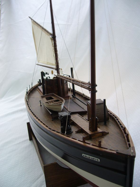
The Motor Fifie Amaranth
JOHN MARTIN, The Wobbly Shipbuilder, makes a welcome return with his construction of the Caldercraft kit
Enjoy more Model Boats Magazine reading in the monthly magazine.
Click here to subscribe & save.
This model, from the Caldercraft Mini-Fleet Series, was to be my next challenge. Regular readers of this magazine will know that I suffer from Parkinson’s Disease, but also that model boat building is both therapeutic and challenging for me.
The model, to a scale of 1:40, has a length of 600mm and a beam of 170mm and was to be a slight change for my model shipbuilding, since it has a moulded hull unlike my previous models which have been plank on frame. However, this Scottish trawler in all other respects is constructed of wood. The first task as always, was to open the box and check all the components against the list supplied. The detailed instructions supplied with Caldercraft (and Jotika) kits, are very explicit, easy to read and understand. The model is designed for electric propulsion and radio control, but I decided to build it as a static model as indeed have been my other models, but with the option of perhaps installing motive power later.
The hull
This was washed with warm, soapy water in order to remove any of the moulding release agent which would have given problems during painting. I also rubbed down the hull with a very fine abrasive wet or dry paper, which would give a good key for the paint and at the same time make doubly sure that the release agents had been fully removed.
The hull was first lightly coated with an undercoat to check for any blemishes, which there weren’t. A thin spray coat of Halford’s white primer is the easiest way to do this, being quick drying and easy to apply. Do check though with any model that you are building that the paints you use are compatible with the material being painted. Sometimes, the finish is excellent and then you discover that it hasn’t actually stuck to the base material. So test on a small and not visible part before painting the whole thing is a good idea if you are not sure.
This was followed by fitting into the hull the ribs and sub-deck in order to give rigidity to the initially quite flexible hull. This was quite straightforward, the CNC cut pieces being accurately cut and fitting together and into place with only minor adjustments. However, before the sub-deck was finally fitted and glued in place it was important to fit the propshaft and propeller. An epoxy adhesive was used to fully seal the hull around the propshaft to hull joint. Although my model was to be static, for the future it might be motorised, so it was best to do it properly at this stage.
The now rigid hull could be top-coated using an aerosol of Halfords satin black (Coal Black No.85). After three coats, the bottom of the hull up to the waterline, was painted using Humbrol enamel of a terracotta colour, similar to the anti-fouling normally used. I am sorry I have forgotten the tin reference number but a check with a Humbrol colour chart should point you in the right direction.
Then came a more difficult task for The Wobbly Shipbuilder – namely painting the white waterline without inadvertently painting any other bits! This was made much easier using a good quality masking tape and I had remembered from reading in Model Boats of such a tape recommended in previous articles. I therefore, bought a roll of 18mm wide Tamiya masking tape (other widths are available) which proved to be an excellent product. Remembering how I had used masking tape when I owned a full sized boat, with a wobbly hand and stretching the tape, it was duly attached to the hull in the desired position after a few failed attempts. The waterline was then painted with three coats of Humbrol satin white.
The printed overlay planked deck was glued over the sub-deck with impact adhesive and the capping rail plus the 72 small gunwale support pieces were duly made and glued into place.The use of pegs and clamps to hold things whilst the glue set proved to be a procedure not ideal for model shipbuilders with wobbly hands, but using cyanoacrylic glues, a bit of luck and patience, this was all eventually achieved. This last photo also shows the unused rudder servo mounting plate installed underneath the wheelhouse aperture. Staining and varnishing finished the deck, bulwark supports and capping rail finished it off very nicely.
Hatches and wheelhouse
Next came the fabrication of these items. Again the CNC cut parts needed little adjustment to fit together properly.
Unusually, the wheelhouse sides were satin varnished and glazed prior to assembly as I felt this as easier for me. The sides were then glued in place, the interior fitted out and the roof added. Any glue blemishes on the joints were touched in, but anyway it all fitted together rather well.
The navigation lights were painted gold and with the appropriate red, green and white coloured lenses. The deck light whitemetal parts were cleaned and fettled, painted satin black and were all fitted to the cabin roof with a very reasonable final result.
When fitting the aft hatch and its wheelhouse assembly, I found that unless it was in exactly the right position, it did not completely cover the hole in the deck. The hatch obviously needed to be removable in order to get to the hull interior should I so want at a later date.
With the hatches complete and the chimney exhausts firmly fixed in place, I turned my attention to the dinghy.
This was straightforward to construct within my limitations and I decided to stain the wooden seats and gunwale medium brown before finishing off with satin varnish. The exterior of the dinghy hull I chose to paint satin white, rather than green as recommended in the instructions. With this type of model, the colour scheme can within reason be whatever the builder might personally choose.
Next came the preparation and assembly of the whitemetal parts for the steam winch, which were also painted satin black before fixing to the deck. The companionway was however rather more challenging. This was due to the radius of the roof and I decided to assemble it on its own base before gluing it to the deck. It was not too difficult forming the radius of the roof with the thin plywood supplied, but I found it difficult to keep it in place whilst the glue was setting. Rubber bands were a great help in solving this problem and after a few adjustments, a successful result was achieved.
During the latter parts of the construction, it was suggested to me by a fellow Parkinson’s sufferer that if I attached athletic weights to my wrists this would dampen out some of the tremor. These weights used by athletes, were obtained from John Lewis (never knowingly undersold!) and I certainly found them to be helpful. I am sure they help strengthen the muscles and I could perhaps get myself a pensioner’s job lifting materials for re-building the Cutty Sark at Greenwich!
Masts and booms
Dowel is supplied for these and it requires shaping. The question arose as to how to taper these without a lathe and my solution was to place the dowel in an electric drill chuck. When the drill was switched on at low speed, I could taper the dowel with various grades of abrasive paper until it was shaped as per the drawings. Obviously, the drill needs to be secured with either the chuck vertical or horizontal and care has to be taken with the dowel not to exert too much pressure when sanding or it could fracture. After staining and satin varnishing, the booms and mast were drilled for the necessary cleats and eyelets. The gaff booms were duly fitted with the wooden jaws and drilled to take the Parrel beads, which would encircle the masts. Here, I decided to make a small modification for my benefit to help with attaching the booms to the masts. I drilled a small hole in the end of the booms and into these holes I glued a short length of brass rod. This was concealed by the boom jaws and with a matching hole drilled in the mast, the booms could be fitted with some accuracy in the correct position. Okay, this is cheating a bit, but seemed to me to be acceptable for a static display model.
The masts were duly stepped into the hull and my thoughts turned to the sail and rigging. The sail supplied needed to be slightly modified to fit the shape of the aft mast and boom. This task was sub-contracted to my wife with her expert sewing skills. The metal rings for running the sail up and down the aft mast were simply made by winding some brass wire around a wooden dowel the same size as the mast.
All was now complete except for the whitemetal name plates. To paint these correctly and finish the model in the manner it deserved, this last piece of work was clearly beyond the ability of The Wobbly Shipbuilder and help was sought from a local artist who is an expert in miniature painting. As would be expected, the results were excellent and finished off my three and a half year’s work. So yes as you have guessed, I am not a rapid builder, but I find it very therapeutic and satisfying to achieve a decent personal final result.
The Motor Fifie Amaranth has now been placed on its own special shelf in the summerhouse, below the ship’s clock and barometer kept from my last full size boat.
I hope the foregoing will encourage similar sufferers with their endeavours. The personal satisfaction of overcoming a disability cannot be readily measured, but I can confirm that it helps maintain one’s confidence in oneself if nothing else.
And now?
On completion of this I was given a new kit for building a small sloop from Nelson’s HMS Victory. The kit appeared to be very comprehensive and the materials of a good quality. However, I experienced problems with the drawings, having annotations etc. all in Italian and the instruction book not in very good English. These were certainly not as comprehensive as the instructions I have been used to with the Jotika kits. I sent four emails to Italy requesting English translations without a reply, so for the future I have decided to buy British!
Double-planking model boats is not the easiest task of boat modellers and it certainly is made more difficult with hand tremors etc. which is a growing problem with Parkinson’s Disease. This handicap together with the language problem was slowing down the Victory’s sloop construction. I therefore decided to find another boat or ship kit supplied by a good British manufacturer. This could be built in parallel with the sloop allowing a choice of work at any one time.
So, I obtained an up to date catalogue from Jotika as I have had very satisfactory results from building the subject of this review and HMS Sherbourne as described previously. Model Slipway was also highly recommended to me and I duly received their excellent brochure, which although charged at £4.50, was extremely good value and probably the best model boat brochure I have seen over the years. This company manufactures and supplies very highly detailed kits for radio control, many containing over 300 fittings. However, I do like working with wood and therefore, finally decided to stay with the Jotika kits, purchasing their kit for S.S. Talacre, a typical single-hatch coaster used in the coal trade. I expect this kit to overcome many of the problems, as I know the drawings will be well detailed and the step by step instruction book easily understood. The hull is of GRP which will avoid my growing problem with double-planking, but much of the rest of the construction will be built from CNC plywood. A variety of white metal fittings, moulded ship’s boats and crew are also included.
I very sincerely must strongly recommend model making and in my case, model boats or doll’s houses by grandfathers for granddaughters! Indeed it is beneficial to anyone suffering a handicap as it helps both physically and mentally with Parkinson’s or other problems. It is excellent therapy and can be started with simple models, progressing as far as the builder wishes.
I now look forward to carrying on my ‘Wobbly Shipbuilding’ and writing again in this magazine.
(As I have written before, John is to be commended for his determination and positive attitude and I hope that this and his other articles are a source of inspiration to all of us – Editor)
********************
Kit details
The kit is available from model trade retailers (who should be the first port of call) or Jotika Ltd in the event of difficulty. A number of excellent retailers advertise in this magazine.
The Motor Fifie Amaranth was built originally as a sailing herring drifter. However, due to the expansion of the steam powered fishing fleet, Fifie owners fitted these boats with small oil powered motors to enable them to compete. Fifie’s were popular and very successful fishing boats. They continued to be built until the early 1930’s and were still earning money for their owners two decades later. This kit is based on a one piece ABS vac-formed hull and CNC cut ply parts. In addition to cast whitemetal fittings, the kit is supplied with a motor mount, propshaft and propeller, vac-formed lifeboat and a pre-stitched sail. The model is designed for radio control or it can be built for display. Part No. 7010, price £114.95, website: www.jotika-ltd.com or see advertisements in this magazine.
