DAVE WOOLEY’s semi-scale model built in eleven days!
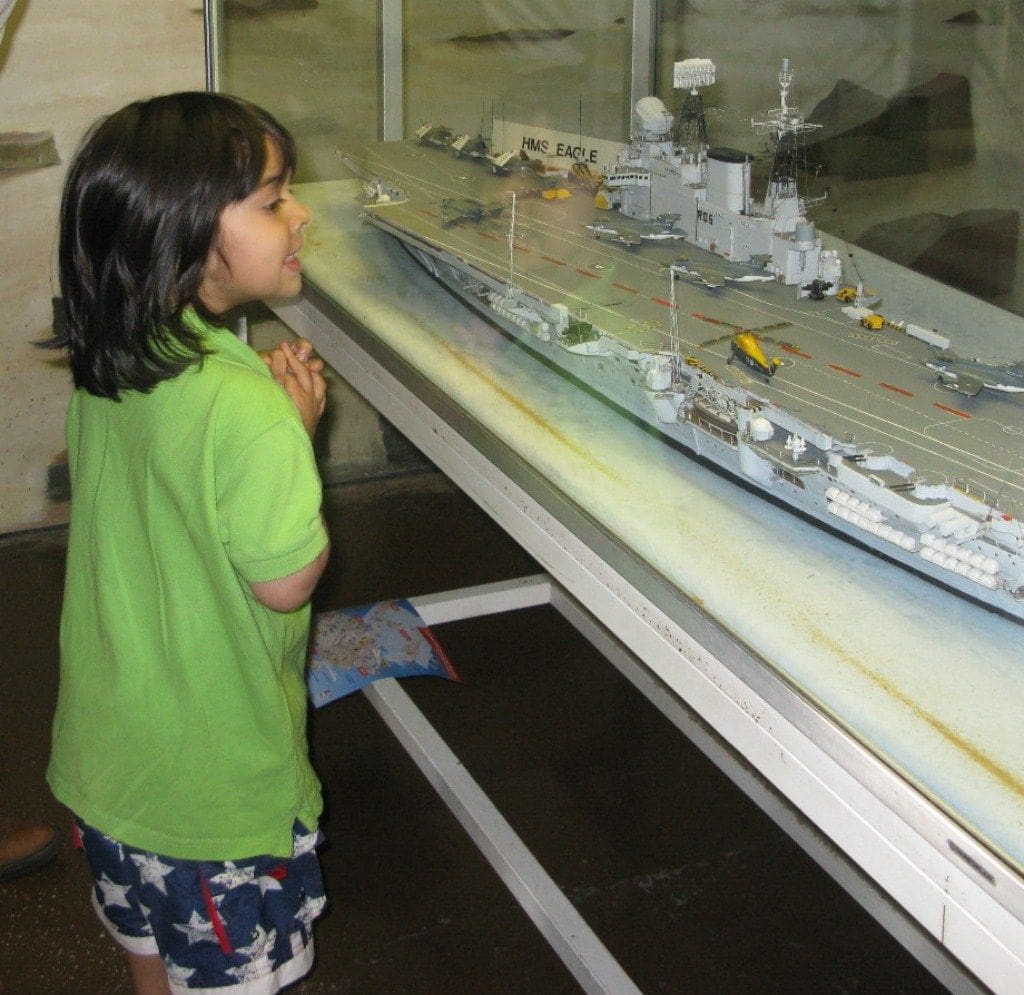
In late 2011, my five year old grandson was introduced to ship models with a visit to the Fleet Air Arm Museum and later his father took him along the Thames to see HMS Belfast and it was here that he first sighted a modern river police launch. His interest in boats and ship models was thus well and truly ignited!
From then on, he made it plain that he would like to have a model that worked and looked like a police boat. Being his grandfather and I suppose knowing a little bit about making model boats(!), I was asked if I could build such a model to further advance his enthusiasm. I hadn’t built a hard chine model for nearly 20 years, so I set about looking for a suitable drawing. Months passed and by late November 2011 I hadn’t cut a single frame until I was reminded that this model needed to be ready for December and certainly by Christmas! So this is the story of a rather rapidly built semi-scale police launch.
Enjoy more Model Boats Magazine reading in the monthly magazine.
Click here to subscribe & save.
Getting started
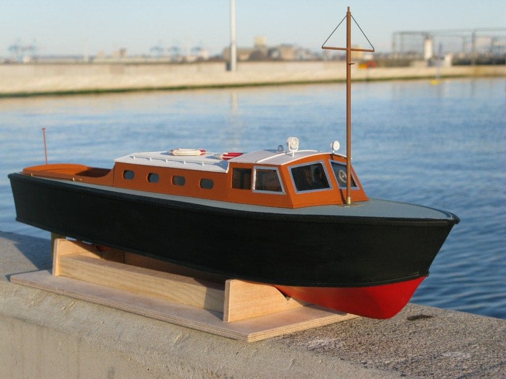
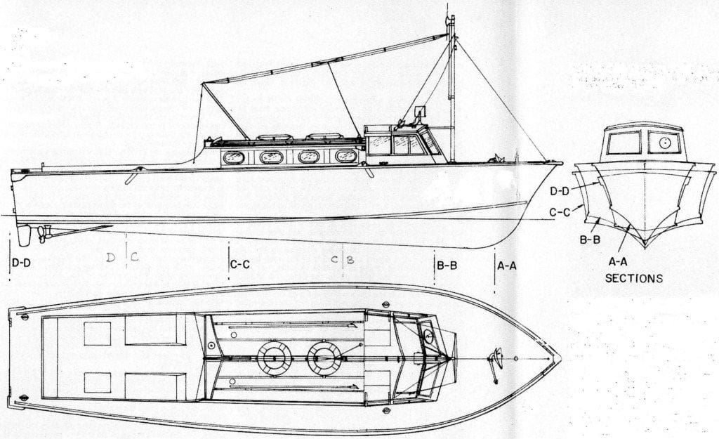
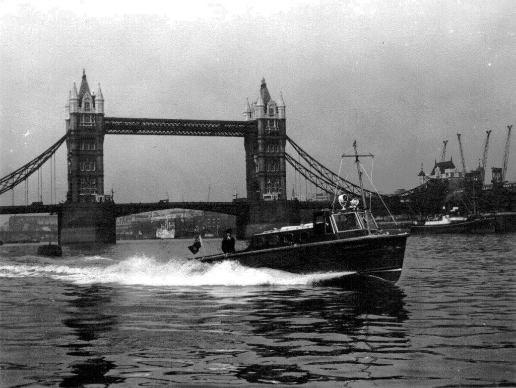
From memory, I recollected that I had seen a reasonable drawing published in August 1976 Model Boats magazine, Photo 1. Although it was an RAF seaplane tender, it followed the lines and appearance of a Thames River police launch of the 1950’s similar to the John Harriott, as in Photo 2. Time was pressing, but scratch build it had to be and the challenge now was to build and paint it, together with a storage box in just 12 days.
A rough working sketch was made and a general layout decided, that would be suitable for the hands of a five year old and his non-modelmaker Dad. So the KIS (Keep it Simple) principle was applied as I had already come to the conclusion that simplicity was the key, rather than scale fidelity. A model 565mm long by 145mm beam would be easy to handle and would look reasonable on the water, whilst being capable of operating in choppy conditions. Anyway, that was the theory!
Materials
For the keel and frames, the materials were 5mm thick balsa and 6mm x 2mm spruce for each of the four main hull edge stringers. The location of the 5mm x 5mm deck stringers would also determine the maximum size of the deck opening. Additional frames were drawn, in which the centres of Frames CB, CC and DC would be removed once the hull and deck were sheeted.
The hull
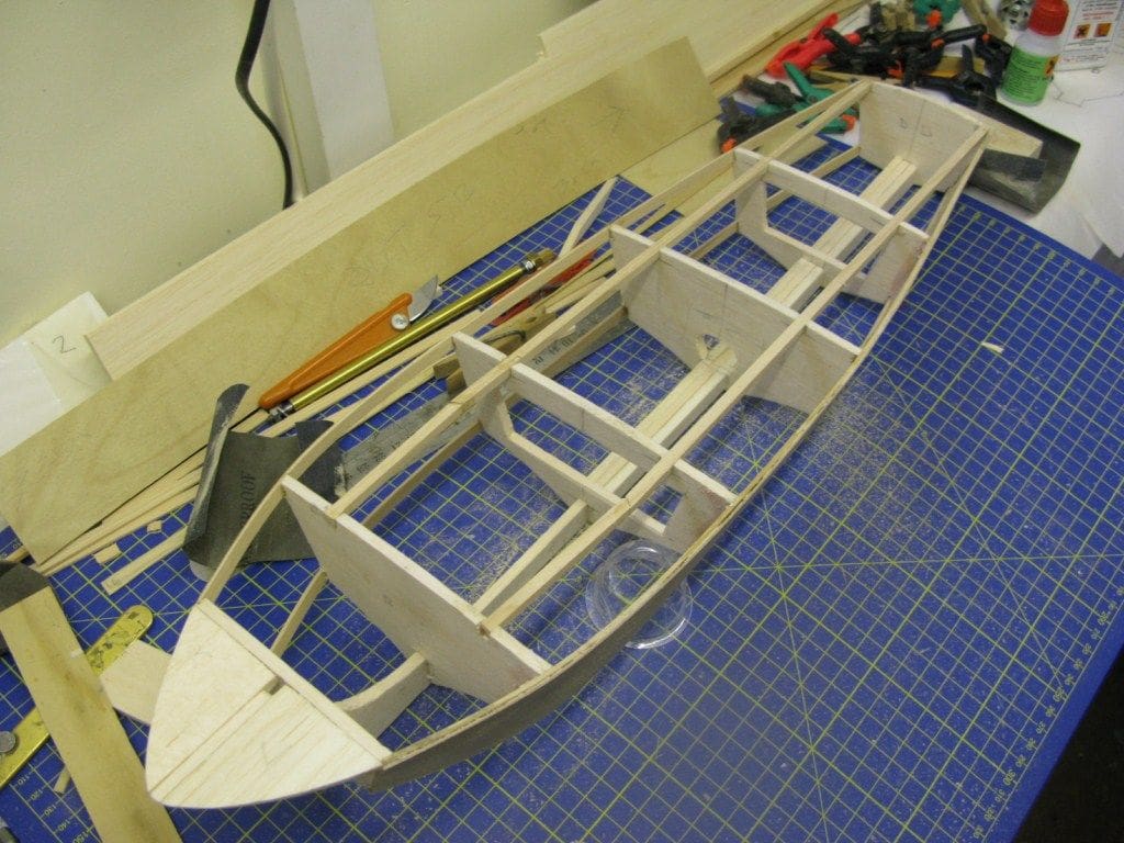
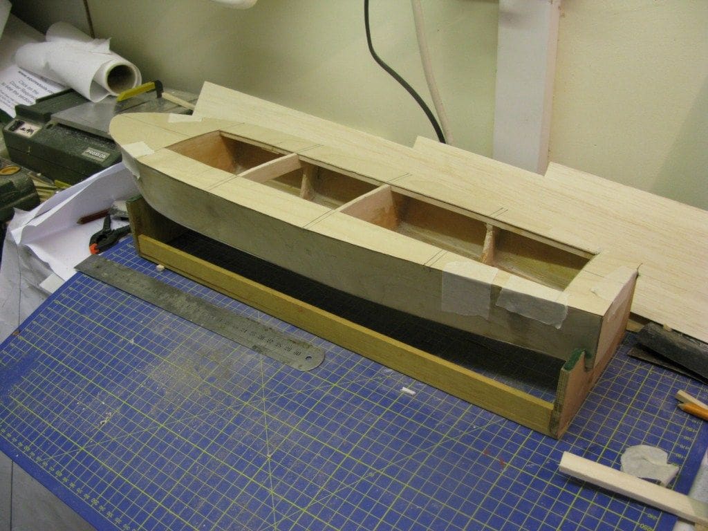
Using tracing paper, the keel shape was copied from the drawing together with the position and angle of the propshaft. The diameter measurements of the propshaft tube were marked on the balsa keel and that section removed. Doublers were then placed across the gap extending from Frame CB to the transom. All the frame positions were marked along the keel and using tracing paper, each frame was copied from the body plan, marked and cut from a 5mm balsa sheet. Slots were cut to correspond to the depth and thickness of the keel and sections removed along the chine line and deck edge to allow for the stringers. Commencing from the stem, each frame was slotted and glued into position along the keel. Once the glue had set, the hull stingers were added commencing from Frame AA. To ensure that the curve of the hull forward followed the top edge stringer, a sub-deck was added to correspond with the thickness of the ply sheets that formed the hull sides. Photo 3 is of progress thus far.
Skinning the hull
Using the hull side framework as a template, 1mm thick marine ply was marked, cut to size and glued in place with Evo-Stik waterproof wood adhesive. These panels did not extend right to the stem, stopping short approx. 3cm because of the curvature that would otherwise be required. Once the glue was dry they were trimmed to size, particularly along the chine line, and the bottom panels added, with a slight overhang on the chine line for later sanding to a smooth contour. The deck followed, which was easy as all that had to be done was to invert the hull over a wood panel and mark on to it the top outer edge with a pencil. Once this deck panel was cut to size, a centre line was marked from which the correct position of the access opening could be determined. The outer edge of this opening in the deck panel had to correspond with the inner edge of the deck stringers, Photo 4.
With the deck now in place, the bow area was completed with blocks of balsa that were glued in place and then sanded to match the hull shape. The last task here was to fit externally two lengths of spruce for the gunwales and two lengths for spray rails along the chine line.
The superstructure
This consists of three distinct sections; namely the forward wheelhouse, an amidships cabin and the aft well deck. It was decided that access to all the electrics and mechanics of the model were best provided for with two removable units, namely the wheelhouse plus cabin, and the well deck unit.
To achieve an uninterrupted motor and battery area required the removal of the centre of frames CB, CC and DC and a floor inserted to the length of the opening, resting on the top of the keel. The sides of this bay were measured, cut and glued to the remaining parts of each frame and the floor, the remaining complete bulkheads providing the ends. Any excess timber was sanded flush with the deck and thus an uninterrupted space was now available to install the running gear and electrics. Due to the depth available within this space, there were no problems with clearance beneath the cabin and wheelhouse upperworks since these were planned NOT to go below deck level. In other words, these would have no internal depth.
Wheelhouse and cabin
These were made entirely of styrene and as I wrote earlier, only extend down to deck level, a 2mm base plate fitting over the motor and battery area. This base was cut from styrene sheet and the shapes of each of the windows of the wheelhouse sides and front copied from the drawing and cut to size. The forward wheelhouse panel is from two separate sections meeting on the centreline with their top edges curved to correspond with the curve of the wheelhouse roof and their bottom edges slightly curved to mirror the camber of the forward deck.
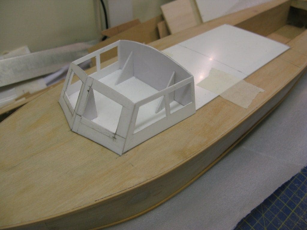
The width of the wheelhouse matches the width of the baseplate which is wider than the opening in the hull. Attached to the underside of this styrene wheelhouse and cabin baseplate is a piece of 10mm thick balsa that plugs snugly into the opening and provides not only a good location for this superstructure unit, but increases its rigidity without compromising on weight, Photo 5.
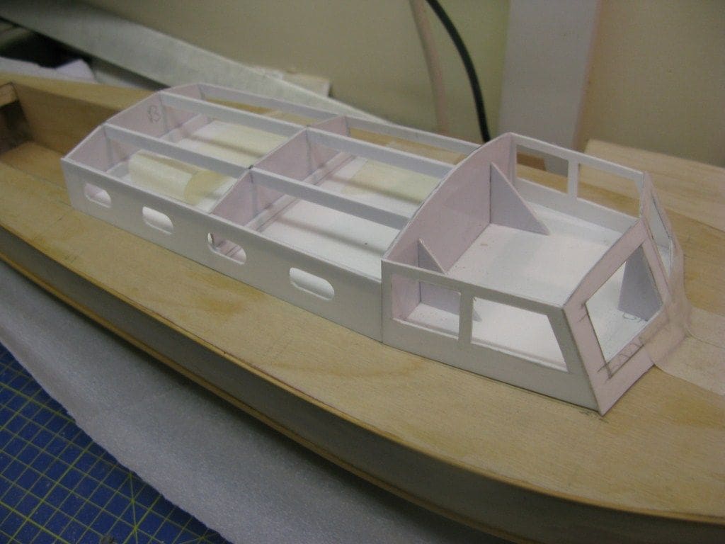
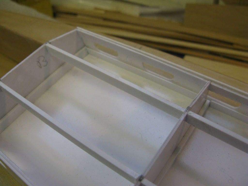
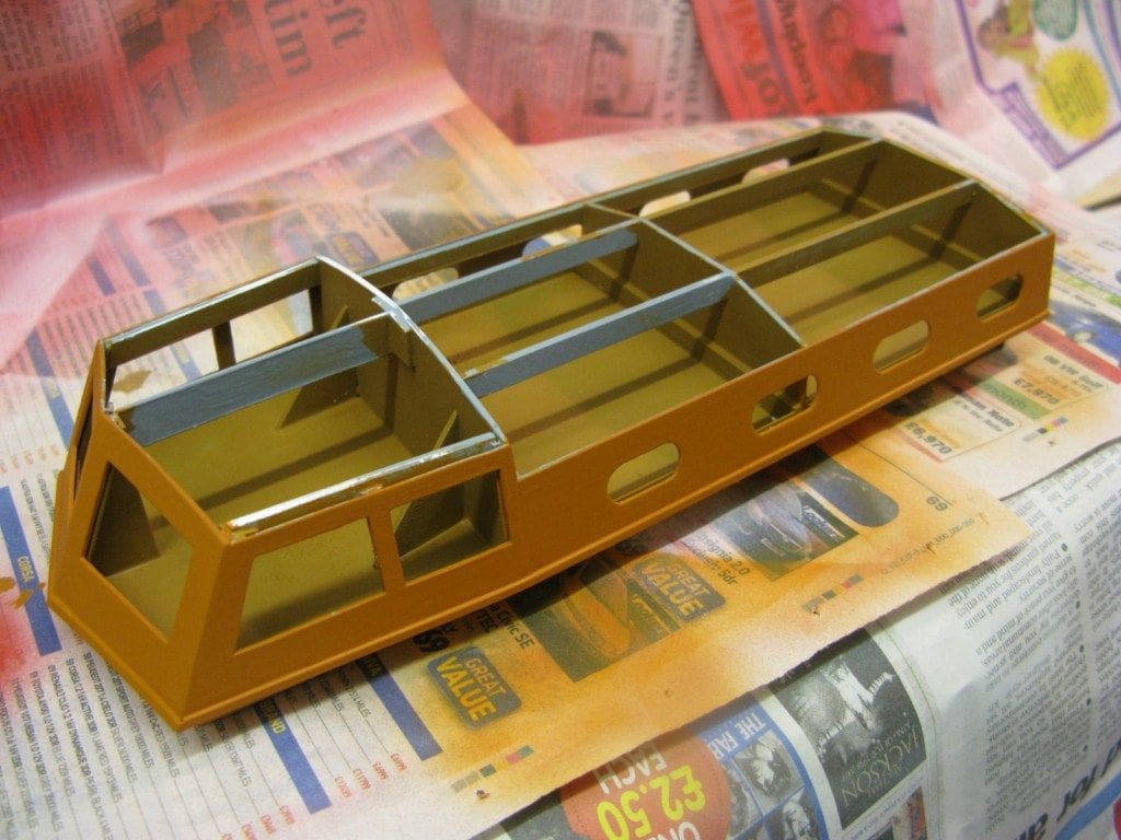
The second task was to construct the cabin which extends rearwards from the wheelhouse. This consists of centre and rear profiled sections, roof supports and the sides with window openings, Photo 6. For ease of construction, the roof consisted of three sections.
Glazing
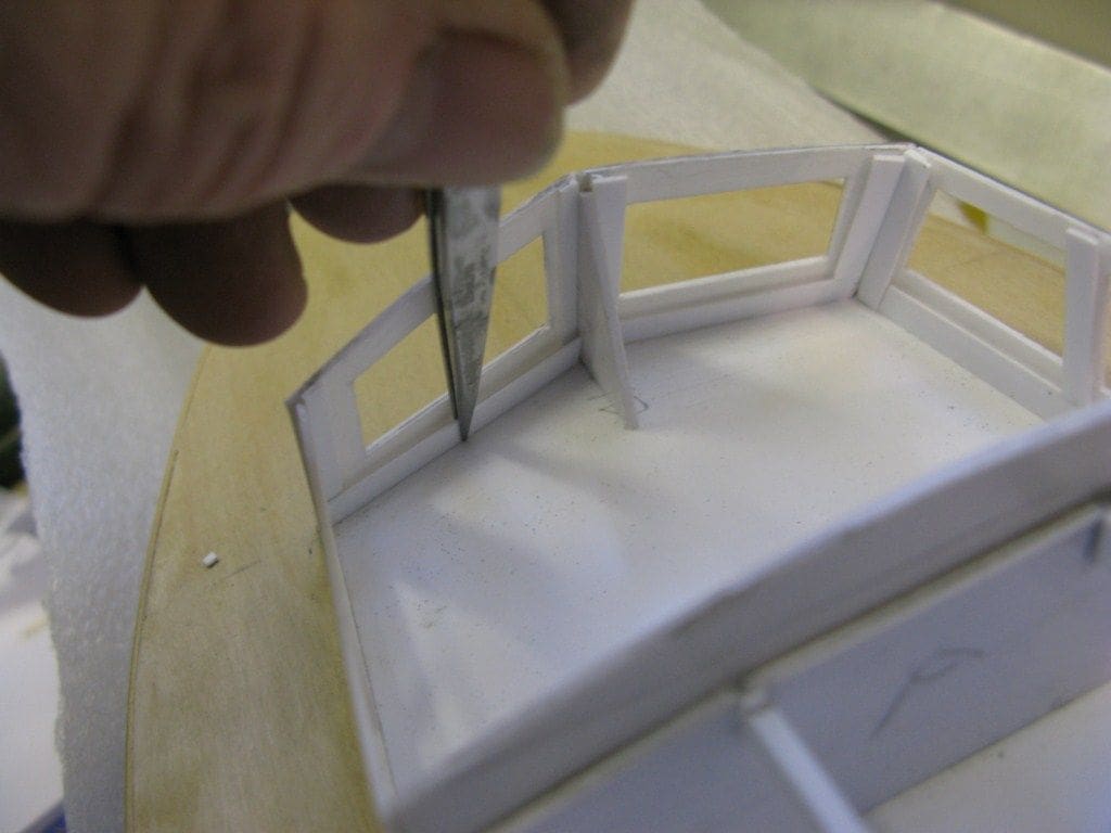
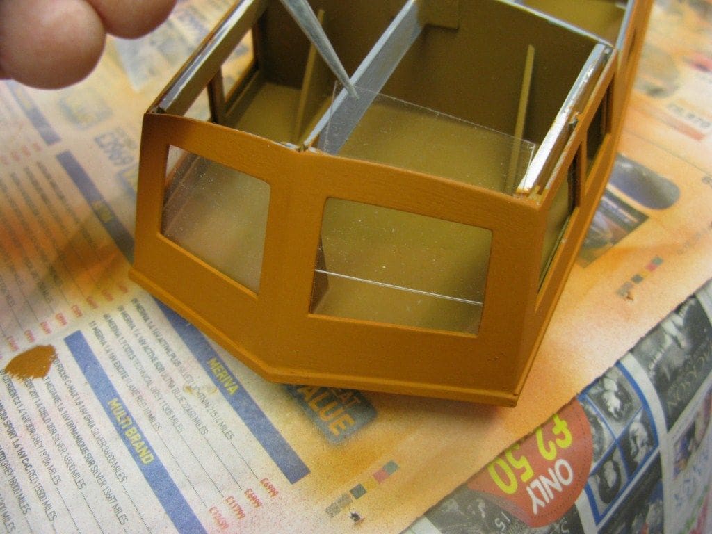
My preferred method when using clear acetate sheet for glazing, is to build internal frames using styrene strip. This eliminates the need for gluing, it being just necessary to slide the cut glazing into the internal frame, Photo 7. A similar method was used for glazing the cabin, Photo 8.
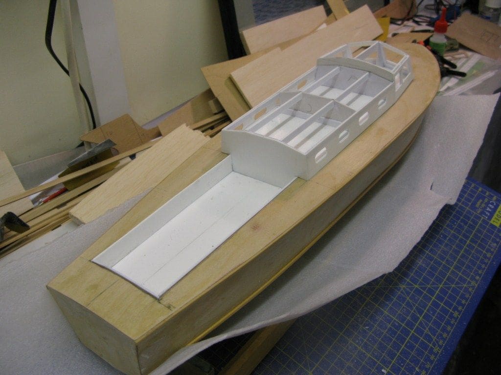
Well deck
I had no information as to the correct depth of the after well deck, but its bottom had in any event to clear the rudder linkage and servo. So, yes it is bit shallower than full size, but has the virtue that it can be removed as one unit. Construction consisted of the bottom, two sides and back section, Photo 9. Around its edge internally within the hull are strips of timber which form a shelf on which it all sits. The sides are extended above the deck to maintain the same line as the forward superstructure base plate.
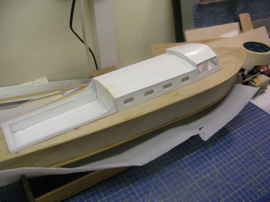
Preparing the roof and well deck sides
The wheelhouse roof was measured and cut to size allowing for a slight overhang on each side and to the front. To ensure that painting of the interior and glazing could be easily undertaken, both the wheelhouse and amidships deck housing roof coverings where made removable and only fixed when everything else was completed Photo 10. Profiled sections were added to the sides of the well deck unit to provide the vertical lip above the deck. Finally, to ensure a good match with the hull a styrene ‘fiddle’ strip was fitted to the edge of the wheelhouse, cabin and well deck sections where they meet the wooden deck, Photo 11.
Fitting out
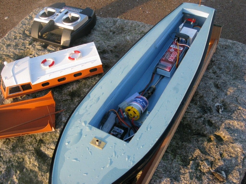
The last stage prior to painting was to install the running gear, rudder, motor, coupling and electrics, remembering KIS! The battery pack is a 1600mAh capacity 7.2v sub-C pack sourced from Component Shop, website: www.component-shop.co.uk. An MFA Torpedo 400 provides the oomph. For speed control an Mtroniks Viper waterproof Micro Marine esc fitted the bill perfectly and for r/c, a two channel Acoms 2.4Ghz combo from Scoonie Hobbies, website: www.scoonie-hobbies.co.uk fitted the bill nicely. Photo 12 is of the complete installation, but after painting! Sorry, I forgot to take the picture at this time.
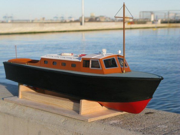
Painting
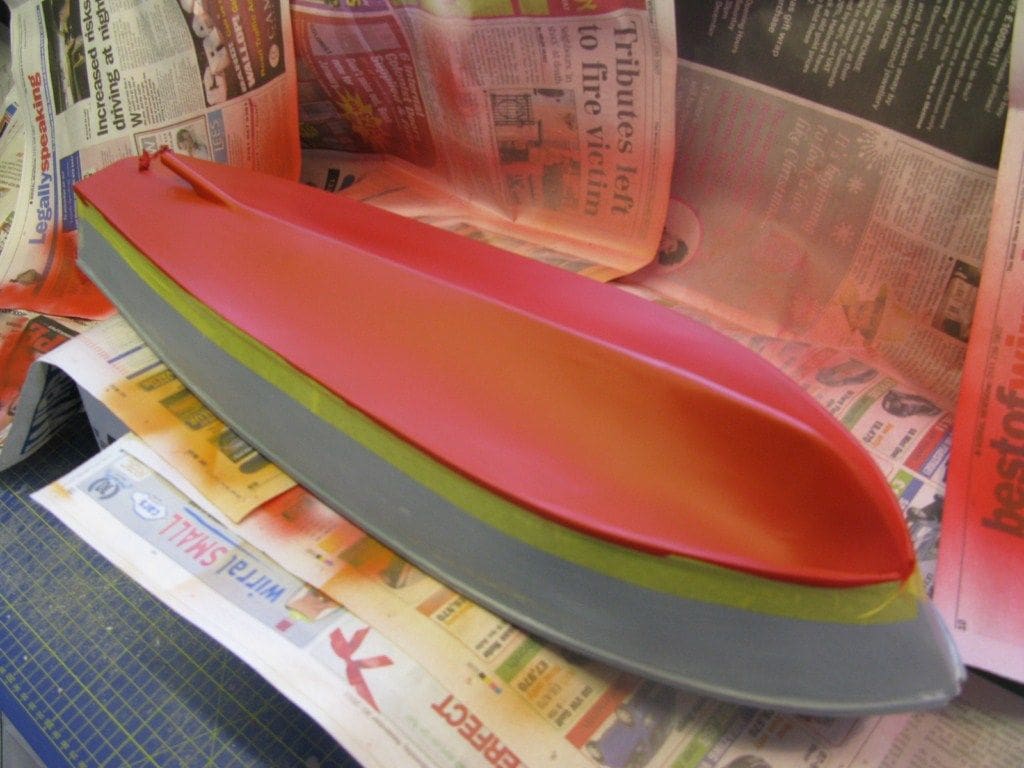
The hull was sanded and sealed with sanding sealer prior to a coat of hi-build primer providing an excellent base coat when sanded smooth with wet and dry paper. Any imperfections on the surfaces were filled with David’s Isopon P38 and also sanded smooth. For final colour coat finishing, the deck and hull sides were masked off and the underside given a single airbrush coat of Revell No.174 Signal Red as in Photo 13. When dry the underside and hull sides was masked off and the deck airbrushed in Humbrol No.65 Matt Aircraft Blue. The hull sides are Humbrol No.33 Matt Black.
The removable complete wheelhouse, cabin and well deck unit is of course all in styrene, so a different approach was required.
First task was to clean this, then apply a coat of primer, check for blemishes and then paint the outer surfaces with Revell No.85 Matt Brown, together with the entire well deck. The inside of the cabin unit was brush painted a slightly darker brown as in Photo 13, and the two roof covers are matt white. I didn’t overspray the whole model with varnish since time was pressing!
Glazing
When the paint was dry, glazing of the windows could begin. Having internal retaining frames made the task very straightforward, All that was required was to slot in each prepared acetate sheet as in Photo 15. As it so happened, because of this system, it was possible to later change the glazing to a darker tinted version which looks better.
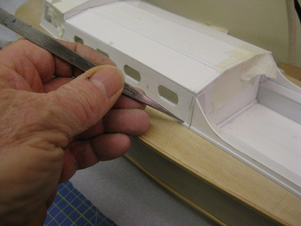
Outer window frames
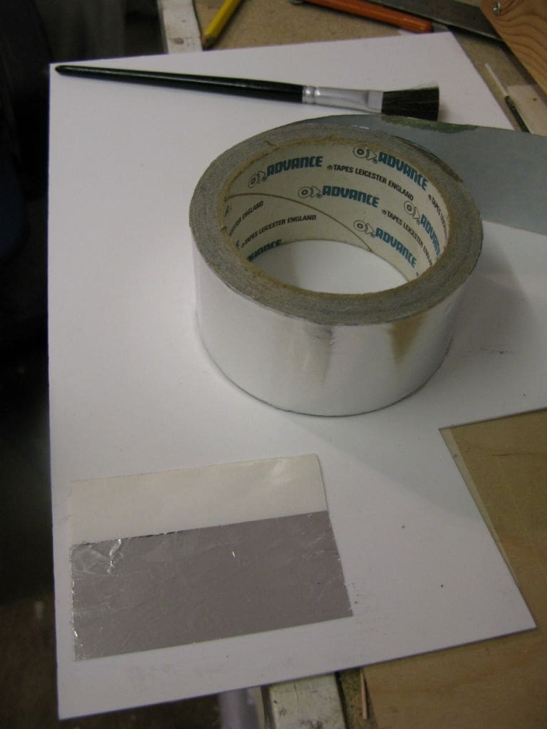
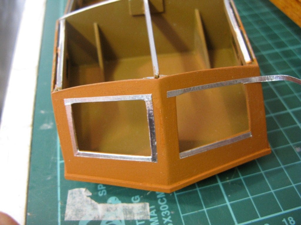
Fitted to the outside of the front and side windows are an aluminium frame. A simple but reasonably effective method to replicate these was sticky backed aluminium insulation tape from Advance Tapes, website: www.advancetapes.com. Each strip was measured to correspond with a window, cut, peeled clear from its backing and fitted, Photos 16 and 17.
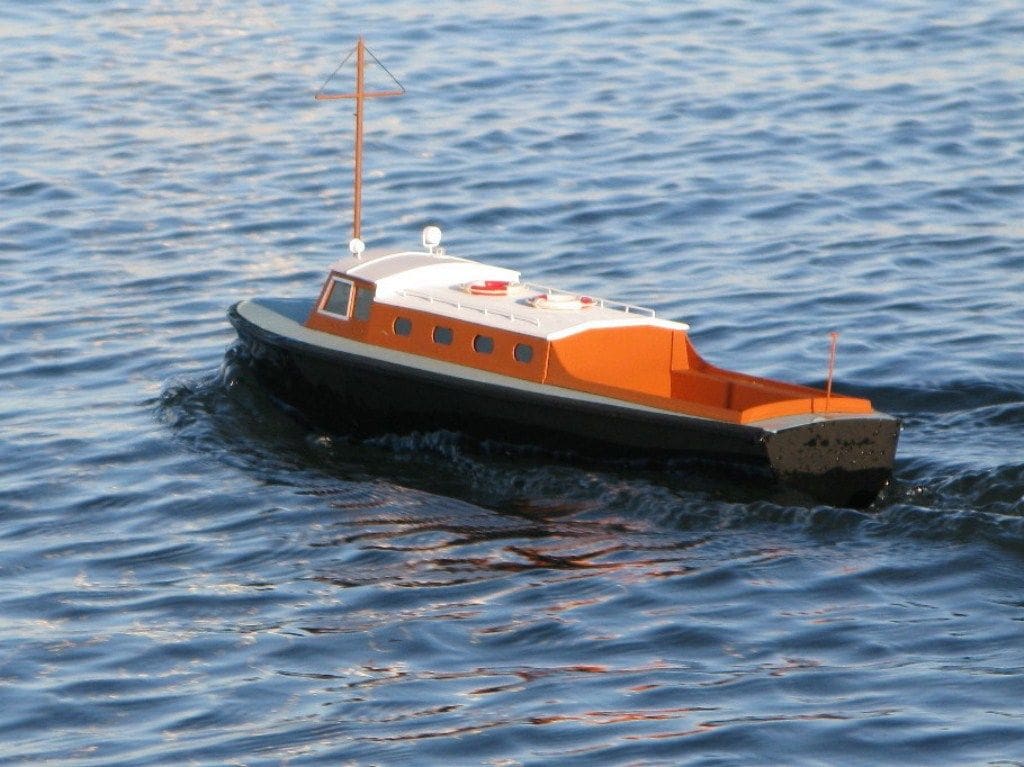
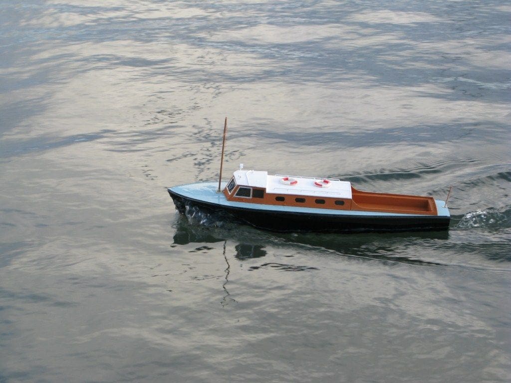
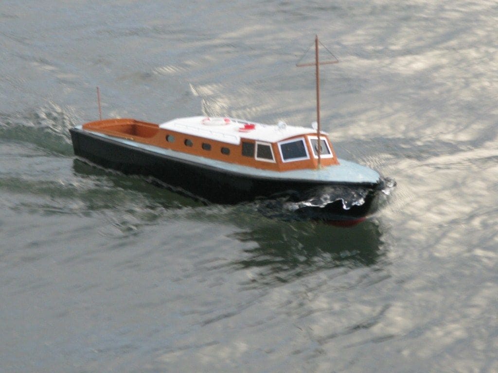
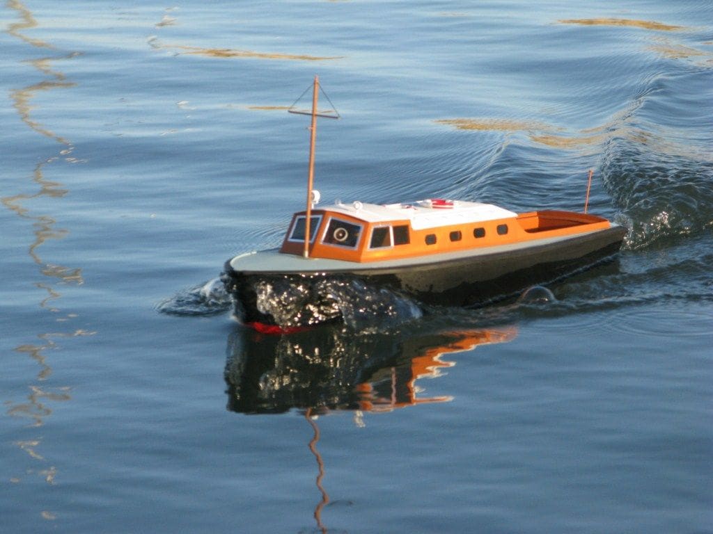
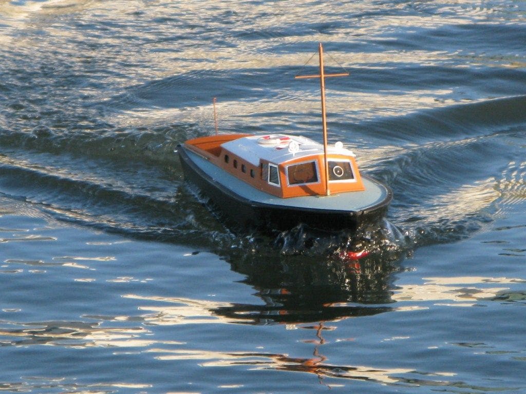
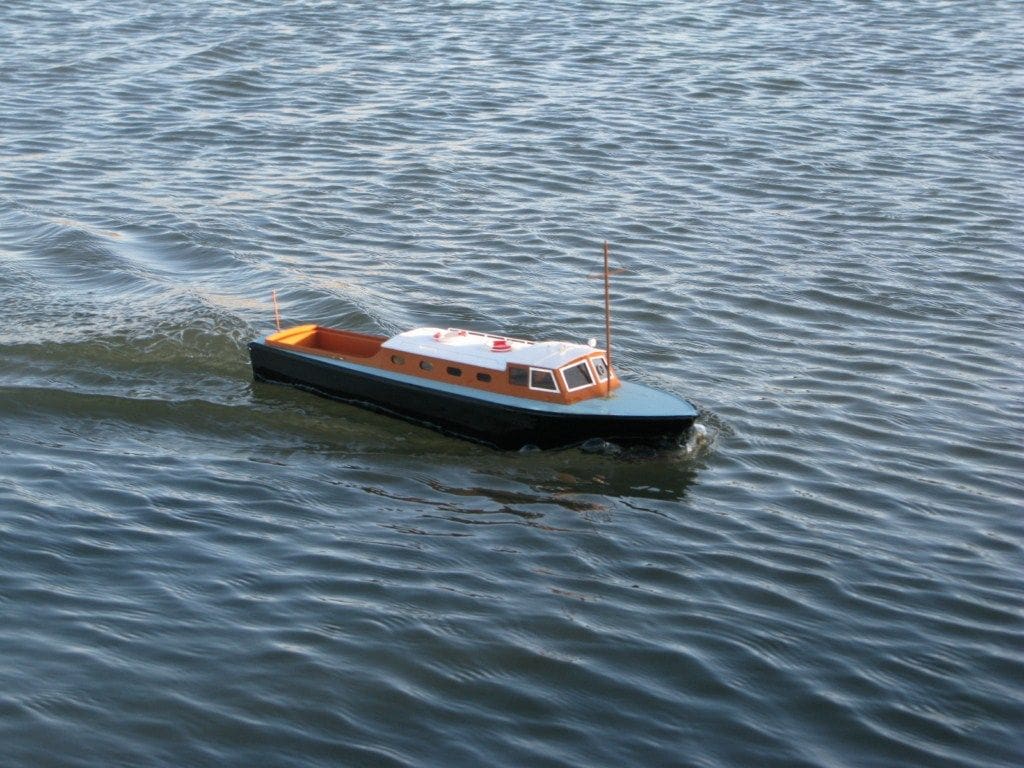
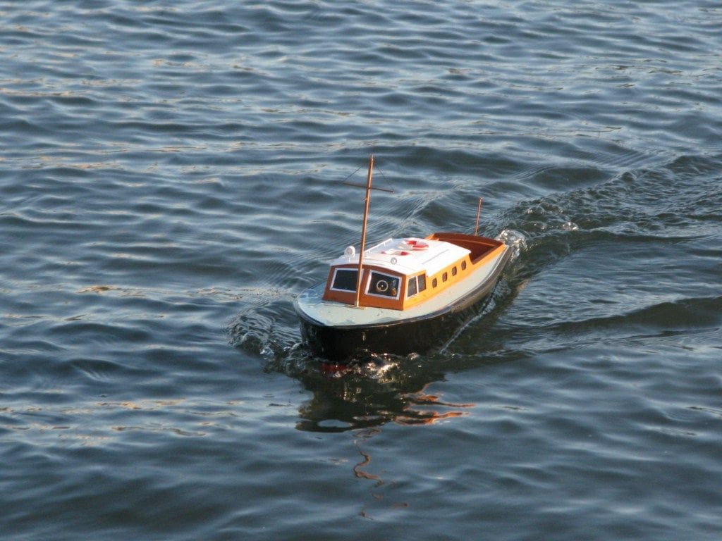
On to the Water
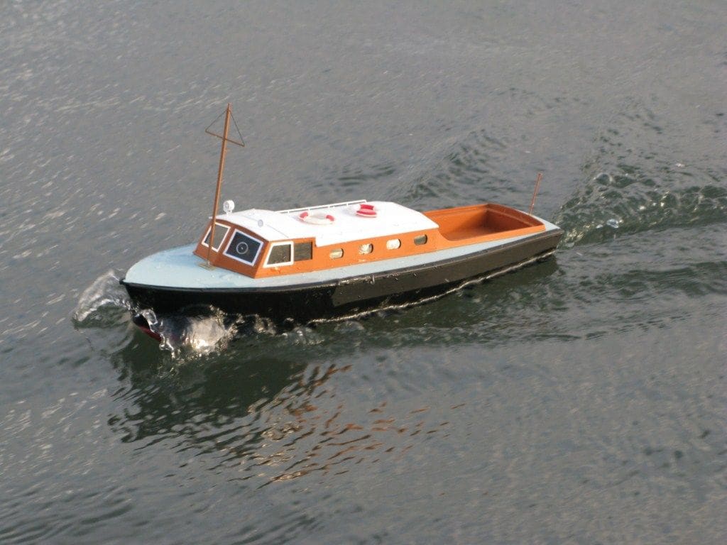
All of the foregoing took just under eight days, Photo 18. Model trimming relied on a simple rule that could equally be applied to many similar hulls. This rule is that the centre of gravity usually equates to a position about 60% of the length back from the bows or alternatively where the propshaft enters the hull. Using my forefingers either side of the hull at about the 60% mark, the battery (which is the main movable ballast item) was shifted around until balance was achieved. This hull is a planing hull and as such with the right propeller will have a lively performance. The plan here was to have a model that was not too quick but would respond well, do tight turns, and for a complete novice be hopefully easy to handle and safe. The results of going for 60% centre of gravity? It ran with enough of a performance to please the expectations of a little boy, but not too much to make it a handful, Photo 19.
Storage and portable case
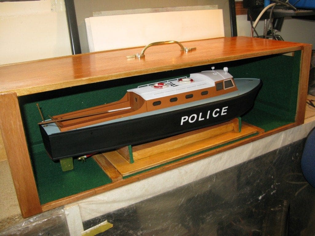
After completing the initial trials. the next essential was to construct a box, light enough yet strong enough to withstand the occasional knock and large enough to store the boat comfortably. To this end, 10mm thick off-cuts of ply were sourced from the local timber merchants. The box has an internal framework plus clearance for the model’s stand with access via an open front that has a lift out 5mm ply panel, Photo 20. It required two days to construct the box and one day to varnish and also dress the interior in green felt. Total cost was approximately £6.50 including the brass handle and felt.
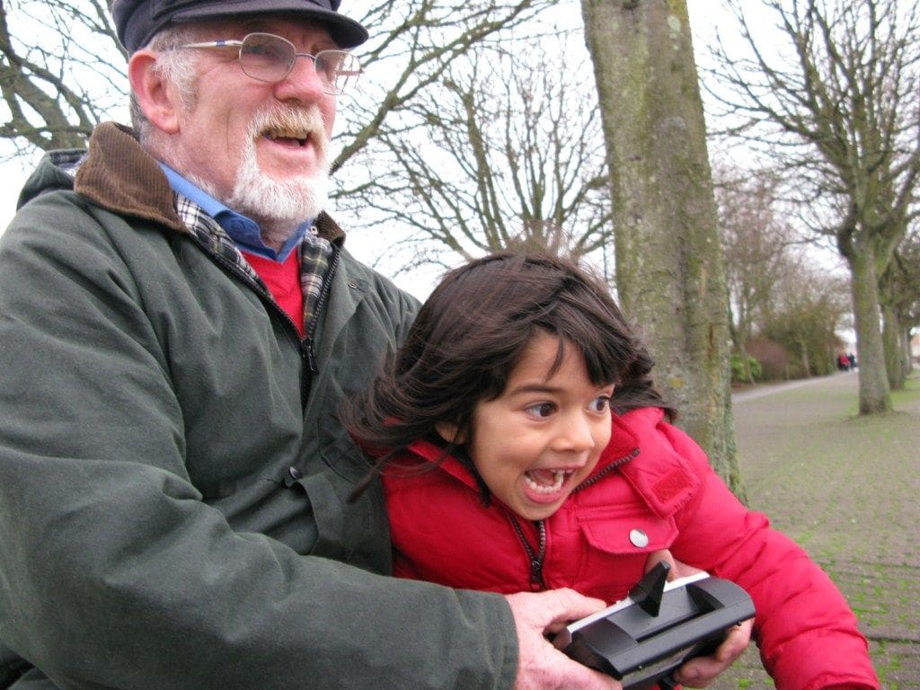
Conclusion
From start to finish the whole project took just eleven days and I can honestly say the project was very rewarding and the delight it brought one little boy and his granddad at Xmas 2011 can be seen in Photo 21. More to the point, sourcing plans and enlarging something from an old magazine can provide a good basis for such a model.