Tamar class lifeboat
TERRY SMALL reviews the Model Slipway kit
Enjoy more Model Boats Magazine reading in the monthly magazine.
Click here to subscribe & save.
The Tamar
The Royal National Lifeboat Institution Tamar class is the result of several years of research and development to produce the new generation of slipway launched lifeboats. The Tamar is virtually unsinkable and if it capsizes it will right itself within a few seconds. These new lifeboats are gradually replacing the Tyne class. The lifeboat includes a computerised Systems and Information Management System (SIMS) that enables the crew to control many of the lifeboat's functions remotely from the safety of their internal cabin seats. Other features include advanced ergonomics that reduce the impact on the crew as the lifeboat crashes through waves and a powered Y class boat stored behind a transom door. This Y class boat can be accessed by lifting a section of the rear deck and then launched and recovered on to a ramp provided by the lowered transom door.
The kit
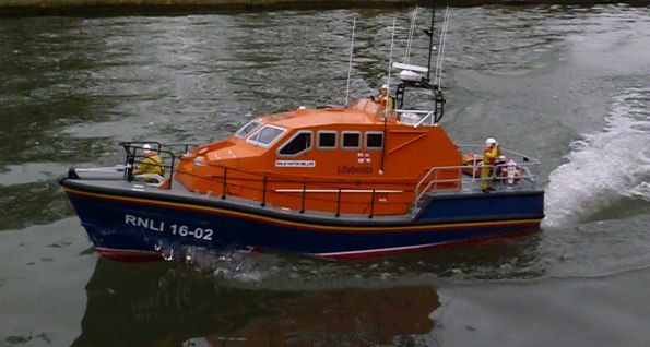
Model Slipway produce high quality kits and were the first to produce a commercial kit in the UK of the Trent class lifeboat. To compliment this they have now produced the Tamar to the same 1:16 scale. Length is 1000mm, beam 320mm with a displacement of approximately 7.5kg. The kit contains all the required parts to build the model to exhibition standard as a functional radio control model, Photo 1. Included are: GRP mouldings for the hull and deck; a comprehensive cast white metal fittings set; CNC cut and printed styrene sheets for the cabin; three large frets of etched brass items with detailed window frames, instrumentation, interior detail etc; some self-adhesive and decal lifeboat lettering and RNLI flags; three sheets of plans and instructions with over 70 isometric drawings for ease of construction, plus propshafts and rudders and other hardware materials complete the kit. Not included are glues, paints, radio control, motors, couplings and other minor functional requirements.
The kit is probably not for a beginner, but anyone with a modicum of model making skills and experience should have no difficulty building this kit to a high standard.
Stand, hull openings and deck edge supports
The hull itself is a really super GRP moulding with all the spray rail detail. Various holes and slots will need to be drilled and filed into the underneath of the stern to install the running gear. A drawing showing all the required dimensions is supplied and was followed to a ‘T’. Always apply masking tape over the areas to be drilled as it stops the GRP gel coat from cracking and also usually prevents the drill bit from slipping when drilling, Photo 2. This is dusty work and it is probably no bad thing to cut all the hull openings in one go to get this task out of the way. Fibreglass (GRP) dust is hazardous, so wear a mask and/or do it outside and vacuum up all the dust afterwards. Any sanding of the top edge of the hull should also be done now, and it can be beneficial to add the deck support stringers providing additional strength to the unsupported top edge. The deck will rest on these stringers made from 2 strips of 3 x 6mm styrene glued in place just 2mm below the top edge of the hull all the way around allowing for the step positions either side. The first layer of strip will require thorough keying of all its contact surfaces. For speed and convenience, the first strip was superglued to the inside of the hull and the second was cemented with traditional polystyrene glue from a tube. Bulldog clips are essential to hold them in place while the glue sets, Photo 3. Please note that the bow thruster holes have been cut and I will refer back to that a little later. For additional support a fillet of Isopon P38 between the hull sides and undersides of the styrene strips will reinforce the joint. Depending on your skill level, you can mix and match at this point in construction because you could install the propshafts and rudders etc before the deck stringers or vice-versa, as it can make it a bit more interesting to ‘chop and change’ a bit.
Rudders
Two brass versions are supplied which need to be modified to represent the correct size and shape of the originals. This is rather cleverly achieved by gluing two styrene outer blades over the original sheet brass blade as in Photo 4. The key here to obtaining sound glue joints is to roughen the brass and inside face of each styrene blade with course sandpaper and use thick viscous superglue. The gap all around the join, due to the thickness of the brass blade, can then be filled with scrap pieces of 0.5mm styrene, allowed to thoroughly dry and then each rudder can be sanded to the correct profile.
Bilge keels and central skeg extension
The main central keel skeg extension piece will then need to be assembled. The two main outer side plates are spaced using printed styrene strip parts, leaving the inside hollow. Once glued to the GRP hull and central keel, it becomes a very strong unit. However, I felt it needed to be ultra strong to withstand the odd knock, so I decided to take the belt and braces approach with a little modification as can be clearly seen in Photo 5. Tubular brass pegs through into the hull help improve its fixing. One of the bilge keels can also be seen just behind my hand and the propshafts are currently just loosely placed, pending proper glueing.
Bow thruster
Having marked the opening on the hull, it is best to drill a series of small holes inside the marked area and file out to the required opening, checking the unit against the hull openings and when it fits nicely, glue in place using five minute epoxy, later reinforced with Isopon P38 car body filler, Photo 7.
Propshafts
The outside of these where they pass through the hull will need to be keyed with rough sand paper then each glued in place with five minute epoxy followed later with P38 filler as extra reinforcement. Each shaft will also require a white metal skeg casting fitted with its flat support locating in a slot filed in the hull bottom. These are best further supported with a keeper wire of 1.6mm rod as indicated in Photo 8. I cannot stress too much the need to get their positions just right before finally gluing in place. It can be handy just to tack these parts in place with a blob of thick superglue and double check the alignment etc., before reaching for the epoxy. In this photo, the rudder tubes have already been installed. Some rather nice vac-formed supports for these are included in the kit.
Transom
Whilst this was all setting, I decided to assemble the trim tabs, their rams and the exhaust outlets, so that I could work out and draw their locations as well as thinking how best to fit them all. Just gluing them on would not be best practice as after a few runs on the water they would probably all fall off! I am a great believer in pinning and gluing things in place and that’s what was eventually done using dome head brass veneer pins where the pin heads can simulate rivets or a hidden brass rod will have much the same effect. This is also where it is best to think ahead as regards painting. Photo 9, has some of these fittings temporarily in place on a trial dry run. Note the trim tabs and their brackets assembled from etched brass parts which will involve some soldering to make the mounting brackets.
GRP deck
One other constructional feature on the deck are the steps between the forward and aft sections. These are vac-formings that just need to be trimmed to size and glued in place, filling any gaps as necessary.
Main cabin
Construction of the cabin at first looked daunting due to all the different angled sections, but once time had been spent studying each assembly stage in the instructions, it all became very clear as most of the complicated parts are CNC cut, so accuracy is guaranteed, also reducing the cutting-out process, thus saving time. It pays (if practical) to assemble the basic cabin on the deck as then everything should be nice and symmetrical. It should be noted that the two main side panels are different in that they have slightly different window spacing, so don’t mix them up. It is vital when marking the insides for the cabin interior base supports that you measure twice and glue once, Photo 13. The rear bulkhead is set at 90 degrees to the base, Photo 14, whereas the front bulkhead is slightly angled, Photo 15. The fronts of the two side panels require a single light ‘score’ to make a sharp bend line as the section in front of the cabin tapers. Gentle hand pressure is all that is required to bend the cabin sides without breaking them. The top sloping faces at the front end also need care, but if you follow the instructions and double check the fit of each panel, then it will all go together like a dream.
Cabin roof and front windows
An internal roof former has to be constructed with two centre cross pieces lengths of 6 x 3mm strip either side glued flush with the top edge of these allowing more contact area for attaching the roof panels, Photo 16. It is essential to get this correct, otherwise the roof panels will not fit into place as they should.. To achieve a better fit of each panel, it is worth chamfering a bevel where it meets its neighbour as in Photo 17 and Photo 18 is an alternative view of that section. It is best (and logical) to get the centre window perfectly right before adding the front side windows. To add support to each roof panel join I used strips of styrene scrap 1mm thick by 5mm wide, as in Photo 19. Once complete, any defects on the joints should be filled and sanded smooth and Humbrol Model Filler has been as good as any in my experience. There is also another option to be considered for either now or later.
There are two storage compartments set into the sides and top of the sloping area in front of the cabin windows. The hatches for these can be either scribed using the paper template supplied or made from thin styrene sheet. The latter option means the hatch covers will sit proud, which is not protypical, so like the transom door, they were marked with a very fine black permanent marker pen after all the painting was complete, Photo 20. The paper template as supplied is too thin and flimsy to ensure really neat lines, so it is best to make a thicker template from domestic cardboard or styrene sheet, then the marker pen has a hard edge along which to run. I stress that this is a matter of choice – there would be no reason why they could not be made to open if you were so inclined and had the patience.
Flying bridge and fittings
This section is just a simple task of ‘box’ building. The floor has to be fitted first using a 6 x 3mm strip across the rear bulkhead as a ledge and it needs to be 1.5mm below the door cut-out panel and must be parallel to the lower floor piece, Photo 21. The liferaft canister box is a straightforward build and has to be glued on the inside of the rear bulkhead, Photo 22, plus other sub-assemblies such as a rope reel box which will later have a half vac formed simulated rope reel glued within it. Photo 23 is a general view of the rear of the cabin and flying bridge. The upper instrument panel is a little more complex in construction owing to the many angled parts requiring cutting from the printed styrene sheets. Once again, chamfering the edges is essential so that each piece fits nicely against the next, Photo 24.
White metal fittings
Model Slipway has a first class reputation for their white metal fittings and this kit maintains that high standard, Photo 25. As usual, the first task is to clean these, removing any surplus flash material and casting lines using fine sandpaper, a file or a knife, finally followed by a polish using a small suede wire brush, so they are ready for painting and gluing. Some of the small fittings can be just glued in position once painted, but the larger and more vulnerable fittings require an additional securing technique. The rear deck capstan, Photo 26, for example had a small piece of brass rod inserted though its base and into the deck.
Etched brass fittings
You could use superglue or epoxy adhesive, but for etched brass to etched brass, solder is in my opinion the best way forward.
Windscreen
The frame is of etched brass and has all the bolt head detail. When removing the main front frame and two side frames from the mother sheet, care is required not to accidentally cut off the fold over tags that will later retain the clear glazing to the frame. I decided to solder the side frames to the main frame first, after confirming the angles needed and preparing a template, Photo 32. As there is no means of securing the complete frame to the cabin roof, I added some small short 0.8mm pins at intervals along the lower edge of the frame, Photo 33. As this was thin and fragile, care was required removing the flux residue and excess solder. It was a simple matter to carefully mark the positions for the holes to match the locating pins. Templates are included in the instructions for each glazing panel which all fitted very well and by just bending over the tabs on the frames were firmly located.
Fenders and baskets
The fender basket has two inner frames held together by three strips requiring neat curves. A spot of soldering is required again and Photo 35 gives you an idea of what is in involved.
Railings
Holes will have to be drilled to allow the stanchion mounting pin to pass through the kicking boards, Photo 37. A few additional small holes were drilled on the inside face of each kickboard base plate, so they could each be pinned for added security as well as being glued to the deck. The angle of each stanchion will need to be set as the per plan.
The bow handrail is made up from lengths of white styrene tube with (once again) 1.6mm wire threaded through it to maintain its shape. Photo 38 is of the finished item.
Rear cross bar assembly
A plan is included to get all the lengths and angles correct, together with step by step progress drawings. Pins through each of the joints enhance its strength. Where two pieces of dowel meet at right angles, an arc will need to be sanded in one section to make for a cleaner joint. The holes can then be marked and drilled to accept the stanchion uprights. To get the holes perfectly upright drilling through both bars, I used a drill stand and a hand vice holding the piece at right angles to the drill bit. The dowel being softwood I decided to start with a small drill diameter working my way up to the right size to accept the plastic stanchion, Photo 40 is of further progress, but please note that you will have to fill some of the butt joints.
Windows
Each window is made up of three parts; the clear glazing and two etched brass frames, Photo 41. As you can see, the clear glazing fits inside an etched surround that fits over the riveted frame outer, thus creating an internal ledge for the glazing to rest against.
Cutting the clear styrene is best done with a new sharp knife blade, firmly scoring two or three times and then snapping out the shaped piece. There is a knack to this, but a file may be required to get to the final shape and there may be one or two disasters along the way!
Painting? Well in theory you could paint the etched brass parts before adding the gazing, but then the glue may well not stick very well. So, the solution was to assemble each frame and its glazing in unpainted form, then carefully mask off the glazing and then spray each complete frame (and masked window) silver. A bit fiddly with the masking, but the end result was worth the effort, Photo 42.
Cabin interior
The dashboard is also a vac-forming which is cut and trimmed to fit inside and over the front of the cockpit face. Likewise the internal companion way is glued to the floor with detail added in the form of a door and hinges from the etched brass set. The whole interior is satin black to make it easier for the crew at night. No instrumentation for the dashboard is supplied, so I photocopied a set from another lifeboat and glued in place. Admittedly, they are not correct for a Tamar, but they look okay from the outside and better than nothing, Photo 45. The floor once complete, simply locates over some retaining tongues and slides forwards to secure. The model builder can add as much detail as he or she so wishes, weight permitting.
The mast
Model Slipway have simplified construction by supplying pre-formed brass tube for the mast hoops, Photo 46. White metal cast pivots are supplied for the bottom ends, and 4mm styrene tube for the cross pieces and radar platform. This is quite a vulnerable part of the model, and to be honest I substituted brass tube for the styrene tube and soldered it all together using the styrene tube sections as templates, Photo 47. None of this is to say the Model Slipway method wouldn’t work, but it was not difficult and since the hard part, namely bending the arch tubes has been done for you, it was all plain sailing (or soldering!). The whip aerials and H aerial are all from the rod and tube supplied, Photo 48. The radar platform itself is styrene and was just superglued on to the tubular base.
Radar, liferaft containers and lifebelts
These are all assembled from vac-formings with no problems, Photo 49. The best way to sand and achieve a consistent flat surface is with a sheet of fine sandpaper taped to a flat surface. Then the joining edges of each vac-forming are gently sanded to a perfect fit by moving the part in a circular motion over the sandpaper. When, for example, the two halves of the lifebelts are glued together it is very important not to apply too much solvent glue as the plastic is very thin and will easily deform if ‘over glued’. The liferaft containers need to be checked to make sure that they will all fit in their stored bin in the cabin rear bulkhead box. I cheated a bit and once each was made, they were all glued together as a block of three containers.
Y-boat
This is a major feature of the Tamar class. Of course you could not make it and simply say it is stowed and therefore hidden, but it is a nice model in its own right. The inflatable hull and outboard motor are each assembled from two halves of vac-formings, Photo 50. As before, it is best to add to one half of each pair of mouldings a reinforcing styrene strip so that 2.5mm of it locates in the other half, Photo 51. Some filling of the joint will be necessary. On the front of the inflatable hull, there is an apron cover to be added after trimming to size. The outboard motor looks very realistic once complete with its control handle and white metal propeller. Other additional detail comes from scrap box items. Once complete, the Y-boat normally sits inside the stern compartment, but it looks rather better on deck than hidden, Photo 52!
Painting
For the white waterline, plus the yellow and red lines stripes on the hull, lining tape was used, of which there are a number of brands in the market place and the choice is yours. To achieve the anti-slip deck effect, Badger abrasive oxide powder mixed with two Humbrol Matt Grey No. 27 paint applied with a 20mm wide brush creates a very nice slightly rough deck, but don’t overcook it! It is best to have a go on some scrap material first to see what finish you achieve. You don’t need a lot of the abrasive powder mixed with the paint and you certainly don’t want it to ‘clump’. Once dry a further couple of coats of the paint (not mixed with powder) are then applied, thinned 50/50. A final top coat of Humbrol Satin Varnish No. 135 mixed with 20% Matt Varnish No. 49 completes the effect.
Fender
This is supplied as a length of D shaped foam rubber. Gluing it along the hull requires the careful application of gel superglue. This is best applied down the centre of the flat side of the ‘D’, just approx. 12 inch lengths at a time, and the rubber is then positioned and gently pressed down. Cutting the mitre joints is best done with a sharp scalpel or Stanley knife, after the rubber is positioned, Photo 54.
Vinyl and water slide decals
A part self-adhesive set is supplied within the kit, but the modeller then has to specify which Tamar his model will represent and source the cabin nameboards, roof numbers, hull numbers and lettering from the suppliers listed within the instruction book. This is not to save Model Slipway money, but because the kit is a model of a Tamar lifeboat of which there are many. The choice as to exactly which one is depicted is up to the kit purchaser.
With self-adhesive decals, each has been machine cut to shape and will therefore only require peeling from the backing sheet, placing in position, firmly rubbing down and removal of the carrier film, Photo 56. Self-adhesive decals do not need a protective varnish coat.
Radio control and motors
When it comes to this, everybody has their own ideas and product preferences. I like total control over a model using a good quality Tx and Rx, plus the electronic accessories ideally all from one source. My usual request to ACTion R/C Electronics (www.action-electronics.co.uk) giving them details of the model, motors used, radio etc., rapidly produced the required information and a clear full colour wiring diagram. With items ordered, delivery was the very next day! The electronics wiring and layout inside the model was then planned and completed. The heart of it all, is a P92 Power Distribution Board making everything much neater. Fuse boards, although not essential, are handy. Batteries were obtained from The Component Shop, website: www.component-shop.co.uk. The two motors currently installed are Graupner Speed 600 ECO running on 8.4v, Photo 57.
On the water and disaster!
I eventually used the recommended standard motors and not unsurprisingly, they work perfectly well and give excellent results. Why eventually?
I have to add that many modellers use brushless motors and they work very well, so this disaster is all down to me. Total modeller’s block set in for the next three weeks before I began to pick up the pieces and repair all the damage, which was:
A very large hole in the hull
Deck to hull joint badly cracked
Superstructure cosmetic damage
Paintwork badly damaged
This all took some time to repair using fibreglass matting, resin and P38 car body filler, plus a total re-spray, almost taking as long as building the model. Now fitted with brushed motors, all is well again, but that is why this review has been somewhat longer in appearing than would normally be the case. As to the cause of the accident, I have to say that I haven’t a clue and with the set-up as noted in this review it is absolutely fine.
Conclusion
Model Slipway should be congratulated on bringing to the modeller what must have been a design nightmare having so many complex angles on the cabin, but they pulled it off and have produced a very high quality model boat kit that was as enjoyable to build as it was to sail – eventually! The exploded drawings, plans and instructions are well prepared and written. The kit is probably best for those with some model boat experience. Where I have deviated, this is just for my own personal reasons. The kit is currently priced at £367. Model Slipway, website: www.modelslipway.com, tel: 01226 770008, have a large range of kits in addition to the 1:16 scale Tamar.


