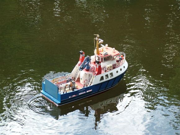
A few years ago when I was building the Metcalf Mouldings Graemsey kit, I thought that the model would be enhanced if the rear loading ramp could be made to operate. Over the years much interest has been shown in the system used for the motorised ramp, as a result of which I have had more than a few requests to do a write up on the system. Being a bit bored and between projects, I succumbed!
Although the method of how to do it did not present a problem, it took me some time to figure out the best mechanical means to use, bearing in mind that the mechanism had to be relatively small to fit beneath the cargo deck of the model. Well, it so happened that in an issue of Model Boats, Model Motors Direct advertised a linear motor that they were about to market. That was it, problem solved! I spoke with Alistair Graham (Model Motors Direct, Keepers Cottage, Home Farm, Iwerne Minster, Dorset DT11 8LB. Tel: 01747 812440 ) who explained that the price depended on the length of screwed rod required. The linear motor plus screwed rod and tapped brass running block came to approx. £22 at the time and proved to be almost tailor made for the job in hand. The length of rod that I used is 8cm, although for other applications different lengths will be more appropriate. The obvious maxim is: If the length of the rod is too long, the run can always be limited with the micro switches, but if the rod is too short then you have a problem. Therefore buy longer rather than shorter, which is blindingly obvious.
Design concept
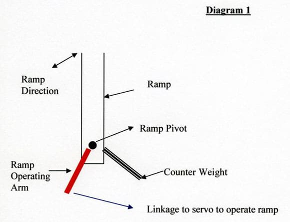
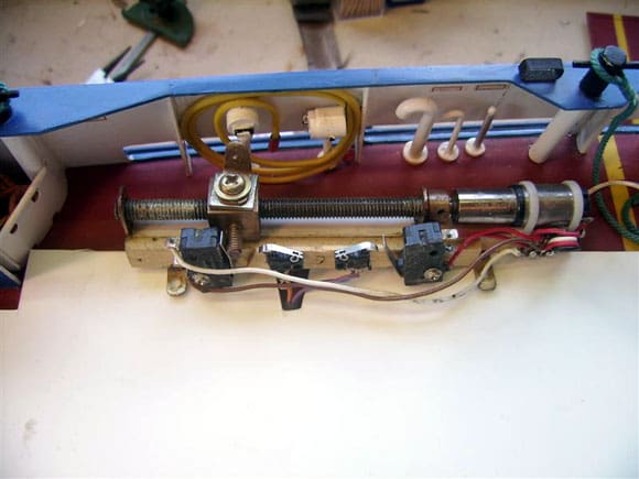
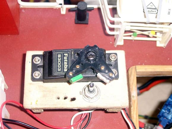
This is simple: As the brass running block travels along the screwed rod, it pulls or pushes an arm on the end of the ramp backwards or forwards, which in turn raises or lowers the ramp. At the same time it also operates the travel limiting micro switches (see wiring diagram and photos). The running block on the screwed rod provides far more movement than a servo arm and allows proper control of the ramp. The voltage provided by 3 x AA pen cells, produced a scale like operating speed for the ramp. When the brass running block reaches the designated limit, its travel is halted by a micro switch. There is obviously one micro switch strategically placed at each end of the travel of the rod, Photo 1.
Enjoy more Model Boats Magazine reading in the monthly magazine.
Click here to subscribe & save.
Diagrams and photographs
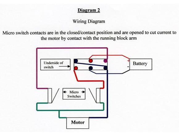
It will be seen from Diagram 1, that the ramp operating arm is set at something like a 30 degree angle to the vertical ramp. This ensures that when pulled forward, as the ramp is lowered, the arm does not override the point of no return. On the other side of the ramp and at a similar angle, but angled the opposite way, a lead counter weight was installed. Obviously the direction of the servo motor is controlled by changing the current to the motor. Now I suppose that this can be achieved by purchasing a proprietary electronic switch, or as I did by using a double pole double throw toggle switch operated by a standard servo (cost £1). The circuit is as in Diagram 2 where it will be seen that as the toggle switch is operated by the servo, it simply changes the positive and negative electrical current to the motor, Photos 2 and 3.
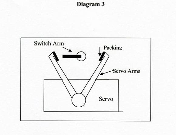
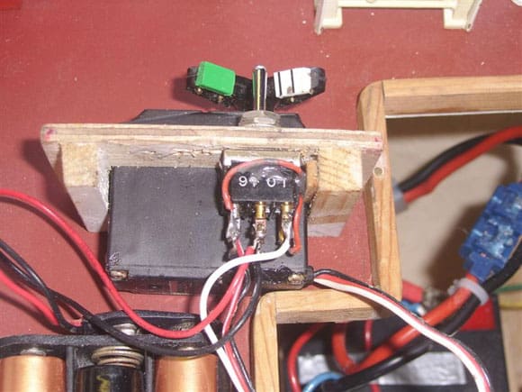
A standard four arm servo output with two arms removed needs to be fitted to the servo itself. Additionally a small amount of packing on the inside edge of each arm needs to be fitted in order to help flick the toggle switch arm to and fro, Diagram 3 and Photos 2 and 3 again. It will be seen that as the double pole switch operates, it reverses the current to the motor terminals which in turn allows the screwed rod to travel in opposite directions. The motor and servo assembly was mounted onto to a piece of 1/8in (3mm) plywood, cut to size and which in turn was sited within the hull. Photo 3 is of the servo and its mounting board, but removed from within the model. The servo can in practical terms be fitted anywhere that is convenient. The linear motor and screw mechanism has obviously to be mounted such that it can easily be attached to the ramp.
Moo and oink!
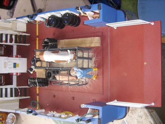
Now for something different: In the photographs two additional miniature micro switches will be seen. On the cargo deck of my model is a pastoral model in which there is a cow and a pig, Photo 4. As the ramp operates, the arm of the running block triggers each of the micro switches in turn allowing the cow to moo and the pig to oink! The sound units were obtained from childrens toys that are normally squeezed to make a noise. Within the sound unit of the toy is a small PC board. All that is necessary to operate the sound unit remotely is to carefully solder a couple of wires from each circuit and connect them to the open side of a micro switch. When the arm of the micro switch is depressed briefly, the circuit is made and the animal noise produced. As an alternative, a ramp operating warning klaxon could be used with perhaps even deck lights wired in.
Conclusion
So, I hope all of this gives you the reader one or two ideas as to how to make things work. It is always worth thinking tangentially (that is a nice word) and looking outside of the normal model boat supply channels for bits and pieces. That doesnt mean to say you should go around Toys are Us testing all the toy animals! Finally, of course the ramp operating mechanism could also be used in much the same way to make a crane, davit, lift, or bow door to function.


