This 1:24 scale model of the Bluebird has been on the market for only a short time. It was primarily marketed as a static model but could be converted for rocket power or fast electric control. This article hopes to show both the detailed static model and the conversion to radio control. First a brief history of the full size Bluebird. It was named by Dorothy Campbell, Donald’s second wife, in February 1955, and during the next twelve years it was to set seven water speed records, with the final speed record of 276.33mph set in 1964 on Lake Dumbleyung in Australia. On 4th January 1967 Donald Campbell was killed while attempting to increase this record on Lake Coniston in the Lake District.
Article continues below…
Enjoy more Model Boats Magazine reading in the monthly magazine. Click here to subscribe & save. After many years half buried in mud at the bottom of the lake an amateur diver named Bill Smith found the Bluebird and later led a team of divers to successfully recover the vessel. Bluebird is now in storage awaiting a restoration project hopefully to bring her back to her original running condition, which when completed will be placed in a museum close to where the tragedy happened. The body of Donald Campbell was also found and was placed in a coffin on the lakebed, later to be raised and buried in the churchyard of St Andrew’s Church, in the village of Coniston.
|
|
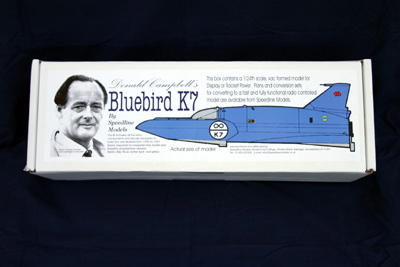
The ModelThe model comes well packed in a box with an illustration of the Bluebird at an actual size of 13 x 5.5ins with a photograph of Donald Campbell. The model is a set of vac-formed sheets from which the separate parts need to be cut out. Two sheets of instructions are also included, one on the history of Bluebird K7 showing the different versions from 1955 up to 1967, complete with line drawings. There are also instructions to build the model as a static model and with rocket power. The second set of instructions show how to install an electric motor and radio control, both are very comprehensive and easy to follow. Photo 1 shows the contents of the kit. Before starting with the building a decision must be made on which model version to use and the year in which it was built, as the parts can then be adapted to suit. The first thing to do was to cut out all the parts from the vac-formed sheets. Lines were indented on the parts to indicate where to cut, and I found the best way to make the lines easier to follow was to run a thin black marker pen along them. Cutting out the parts was done with a sharp craft knife, being careful only to lightly score the plastic and then cut deeper with several cuts of the knife. Trying to cut in one go will produce a jagged finish and may damage the parts. Photo 2 shows all of the parts cut out.
|
|
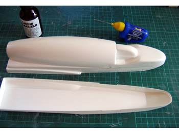
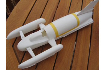
AssemblyWith the parts cut out it was time to start the assembly, but first I decided on the glue to use. As recommended in the instructions I used liquid Plastweld which can be obtained from model shops and is a plastic solvent glue which works best by capillary action when gluing two plastic items together. But a word of warning, do not overuse on ABS plastic as it can melt or deform the material. I also used Revell Liquid Contacta Professional for the stronger joints as this has a very fine nozzle for accurate application onto joints etc., but it takes longer to set and may require clamping parts together. Photo 3 shows the two glues with the first parts ready to join. The two halves of the main hull were the first to work on and with the edges of the parts sanded level they were glued together and left to set, as were also the parts for the sponsons (outriggers) and the rear fin; these can be seen in Photo 4. The sponsons were made from two parts of vac-formed ABS plastic, jointed and made watertight. With the main hull and the sponsons parts joined they need to be fitted temporarily to the spars, wood dowels that pass through the hull and into each of the sponsons. These must not yet be glued as the spar covers need to be fitted. Photo 5 shows the dowels and sponsons. The spar fairings need to be fitted and again these are made up from two parts of vac-formed plastic and glued together. These parts are probably the most important to get right as they have to be trimmed to fit as near as perfect to match the contours of the hull and the sponsons. When happy with the fit they were slid over the dowels and all were glued together as can be seen in Photo 6. Any slightly open joints were filled with plastic filler. When working on the front of the hull I turned the hull upside down and fitted the planing wedge on the underside of the nose. I decided to make this wedge from balsa, (not provided in the kit, but a wooden wedge is) and faired in with Isopon as can be seen in Photo 7. The rear fin is also in two parts that are glued together and sanded to the shape of the hull and then glued in position. To finish this section of the building the main access panel on the hull was cut out and held temporarily in place with masking tape, also the cockpit cover was temporarily fitted, but more on this later. Photo 8 shows the bare assembly ready for the next stage.
|
|
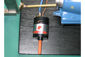
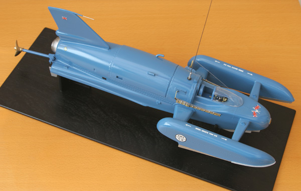
Extra detailingNow is the time to mention that I wanted to add some extra detailing not included in the kit. Most of the items are included in the kit but as different materials to those that I used. The cockpit cover is vac-formed in white plastic and I decided to make a clear canopy. Having cut out the original I made a mould of the canopy with Isopon and when cured I took it to our local model shop (Mainly Models of Hitchin) who vac-formed the canopy in clear ABS for me. This looked much more authentic. Photo 9 shows the original canopy and Isopon mould. Also I made the jet engine cowls to simulate the prototype; these were from litho plate and fitted together with the brass rudder and stabiliser fin – the templates for these items are provided in the instructions. I also decided to simulate the rivets around the major parts; this was done by hand with Superglue and a cocktail stick, slow but effective. See Photos 10, 11 and 12. Also the interior of the cockpit was detailed with a seat, instrument dials and the Perspex spray guards along the side of the cockpit. These can all be seen in the general photos. PaintingNext was the painting, and in the true style the model was carefully sprayed in the correct blue colour, appropriate decals provided in the kit were added and then given two coats of gloss varnish. All paints used were Humbrol enamels. Finally the canopy was fitted and my static version was complete. Working versionThe model cried out to be a working version and the separate instructions showed how this could be achieved. This called for some very careful attention being as the model was complete and painted. Firstly the prop shaft had to be installed; a prop tube and prop specially made for this model can be obtained from Prop Shop. The hole for the shaft was drilled into the hull and an electric motor mount installed in the hull, there are templates provided in the instructions. A fast electric motor 400JR from Midway Models was installed using a flexible rubber tube coupling from SHG Supplies. The motor, prop-shaft and propeller can be seen installed in Photos 13, 14 and 15. The radio control side of installation was done using equipment that I already had, but any combination of equipment can be used, keeping the weight as low as possible. I used a HiTec Little Gem receiver that can still be bought in four-channel mode from Scoonie Models, a small 30amp model aircraft controller (reverse is not required on this model) and a 6 cell 300HHA battery and a micro servo. These items were purely my choice but any other combination could be used. The battery was wrapped in foam and sat at the front of the hull under the cockpit, and the other equipment was mounted on with double-sided servo tape. All the R/C equipment can be seen in Photo 16. Last of all was the access panel. I decided not to drill and screw fix the panel but to simply seal the panel to the hull with low tack clear tape as I felt that this did not spoil the appearance and could easily be removed and replaced during charging the battery and switching on the R/C equipment.
|
|
ConclusionSo there we have the finished model but now for the big test, on the water. Bluebird ran quite smoothly, albeit rather fast. The model has to run on calm ripple free water and the power needs to be applied gently from slow to full speed. If full speed is applied at the start the hull is liable to dig itself into the water. Do not expect to do any tight turns with the rudder provided, although a rudder extension could be fitted, as the prototype was designed to run at high speed in a straight line. This gave a truly spectacular performance. No pictures I’m afraid, as it is a little difficult to operate the controls of a fast electric model and a camera at the same time! Incredible value for money whether building as a static model or radio controlled, with plenty of scope for extra detailing. I look forward to the next model from Speedline. Available from Speedline Models, Windsor End Cottage, Windsor Street, Burbage, Leics. LE10 2EE. Tel: 01455 637658. Email: [email protected]. Price is £29 plus p&p. AcknowledgementsCanopy: Mainly Models, 66 Hermitage Road, Hitchin, Herts. Tel: 01462 422204.
|
Speedline Models Blue Bird
by
–
Advert
Enjoy more Model Boats Magazine reading every month. Click here to subscribe.
Article Tags:


