Some people seem to have difficulty in coming up with ideas for their next models. I’ve even seen people pleading for advice on internet sites. Maybe I’m lucky in this respect as there is never a shortage of possible prototypes to build. In fact there is a drawer in my filing cabinet that is packed with folders full of ideas, sketches and draft plans, enough to keep me going for a couple of decades.
What actually sets me off building a new model can vary widely. Sometimes it can be part of a logical path, maybe a series of related models or a development of a previous design. A few times it has been because someone has annoyed me by saying that something is impossible to do, the proverbial red rag to a bull! In this case it was a minor irritation with all the steam powered models I had built previously.
All my steam experience has been gained with small single cylinder oscillating engines. They are very simple, but still have the appeal of live steam with the characteristic smell, smoke and noise that electric models, however practical can never produce. On the basis of a pleasure/cost ratio, these simple steam plants are hard to beat. Yet, they do have one drawback in that there is no possibility of controlling the engine. You might be able to slow these engines down a little, but if it stops, self starting is not one of their features, neither is reversing!
Enjoy more Model Boats Magazine reading in the monthly magazine.
Click here to subscribe & save.
Cheaper solution
Thus far all my steam powered models have had rudder only control as represented by ‘Beadle’ in the May 1997 Model Boats and ‘Sabina’ in the December 2003 Model Boats issues. They were still great fun to sail but you always had to remember not to sail it into any position they could not sail straight out of. Likewise, any attempt at a steering course had to be undertaken at full speed, an interesting but hardly relaxing experience. One obvious answer was to move up market to something like a twin cylinder engine with throttle and reversing controls.
A twin cylinder engine did not appeal to me for a couple of reasons. Having two nicely run in steam engines, I really could not justify the cost of another one. A larger and more powerful steam plant would also probably demand larger and more expensive models than I really wanted to build. My sailing sessions usually involve two or three different models, so a steam powered one is at best, used as a pleasant interlude between sailing other models. This does not seem to justify spending a lot of money on any one model.
Another reason was professional vanity. Being an engineer I like to solve problems without throwing money at them! I cannot remember who said that ‘An engineer can do for 25 pence what any fool can do for a pound’, but it’s a sentiment I’ve always tried to follow. So, the problem was how to control the speed of a model powered by a steam engine which has to run continuously, ideally being able to stop and reverse its motion. The obvious answer was to look at how others have attempted this.
A gearbox and clutch mechanism would do it, but looked awfully complex and expensive to make. A variable pitch propeller had the same problems, but the idea did keep me occupied for a few hours. Some form of ducting with swivelling nozzles, shades of the Harrier jump jet, might have been more practical, but it always seemed an inelegant solution. Thus, I ended up with the idea of a Kitchen Rudder and a quick search on the internet located details on the Wikipedia site.
Outside the box
Kitchen type rudders employ two curved blades either side of the propeller. In the ahead mode, these blades act like a conventional steerable nozzle and should give good manoeuvrability to any model. By closing the rear edges of the blades together, in effect forming a solid cup, the propeller’s wash is redirected forwards and causes the model to move astern. Intermediate positions of the blades can be used to control the speed of the model without altering the speed of the engine. This looks a good idea, but……..
Using two servos it was not hard to see how to make a mechanical linkage that would operate a Kitchen Rudder. One servo could cause the two parts of the rudder to move together and control steering, the other servo causing the parts to open and close thus controlling speed and astern. Whilst it looked workable, it was going to be bulky and more complex than I normally prefer.
In one of those ‘light bulb above the head’ moments, I realised that this was the same sort of mechanism that our aeromodelling cousins had used to combine elevator and aileron functions (the control surfaces then being called elevons ). Nowadays this effect is obtained not by mechanical mixing of functions, but through the magic of transmitter electronics. Flick a switch on the transmitter and two servos will either rotate together or in opposite directions as the transmitter controls direct.
On the bench
Now I have used this mixing of transmitter controls before, but this was to drive and steer electrically powered models. By using two independently controlled motors to drive the propellers (Jenny Sue 2 – February 2004 Model Boats) or paddlewheels (Tipstaff – April 2005 Model Boats), elevon mixing in the transmitter produced extremely manoeuvrable models that were great fun to sail. The question was: would this mixing allow two servos to operate a Kitchen Rudder?
Before readers try to point out that this form of transmitter mixing must demand the use of expensive and complex computer radio outfits, let me say it doesn’t. I bought one of the Hitec Ranger III outfits when they first came out some years ago. They offered a three function 40 MHz FM radio for little more than the basic 27 MHz AM outfit price. They featured servo reversing, nothing special there and Adjustable Travel Volume (allowing the servos movement to be reduced) which was nice. Even better was a small On/Off switch in the back of the transmitter case for this ‘elevon’ mixing function. As I write (July 2007), this r/c outfit is still available, so if you are in the market for a new outfit and are prepared to pay a few pounds more than the price of the cheapest gear your could buy, then the Hitec Ranger III is highly recommended.
Laying receiver and servos on the bench, the elevon mix was switched on and the transmitter sticks stirred around. Much to my delight it looked like they could be used to control the two parts of a Kitchen Rudder set up. Depending upon the orientation of the servo and tiller arm linkages, some care would be still be needed to ensure the correct movement of the servos. But, this would be little more than you have to use with a conventional rudder set up.
Simplification
I know my limits so there was no way that I was going to attempt to make the complex curved parts that a real Kitchen Rudder requires. After a little experimentation it looked as if two simple flat rudder blades, in other words conventional rudders, might do the job almost as well.
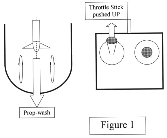
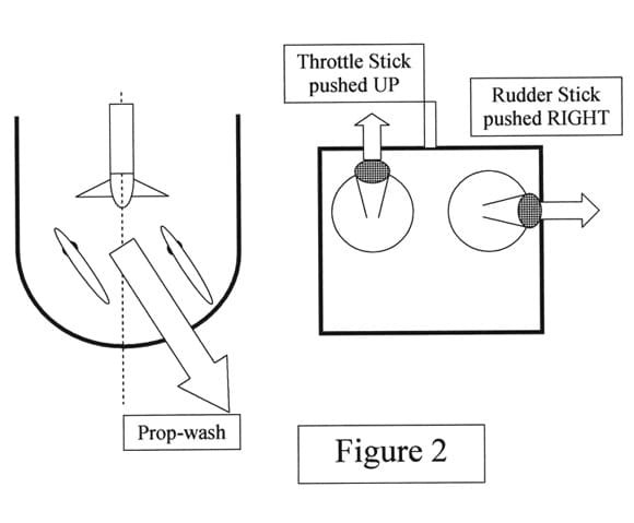
With the throttle stick on the transmitter pushed fully forwards, the two rudder blades would be parallel and create a channel down which the propeller stream would flow, Figure 1. Moving the rudder stick on the transmitter ought to deflect the blades and hence the propeller stream, so turning the model, Figure 2.
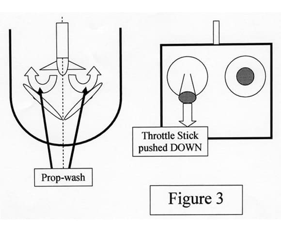
Pulling the throttle stick fully back should bring the rear edges of the rudder blades together and, hopefully, deflect the propeller stream forwards and so create astern motion, Figure 3. With the throttle stick at some intermediate position, i.e. with a small gap between the rear edges of the blades, the forward and astern reactions could be balanced to hold the model stationary. Well that was the idea!
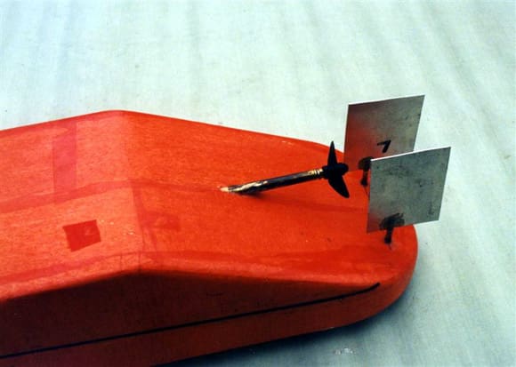
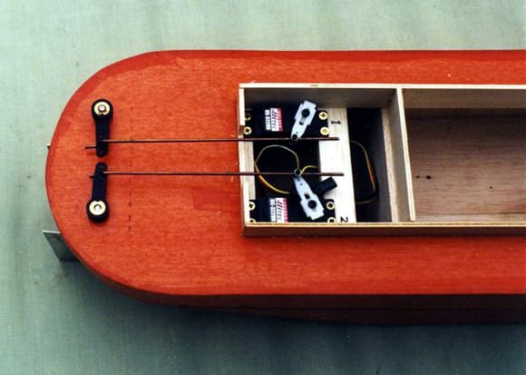
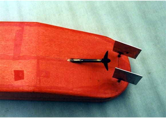
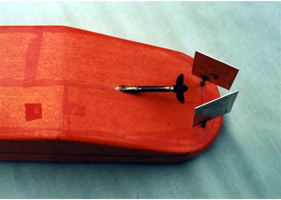
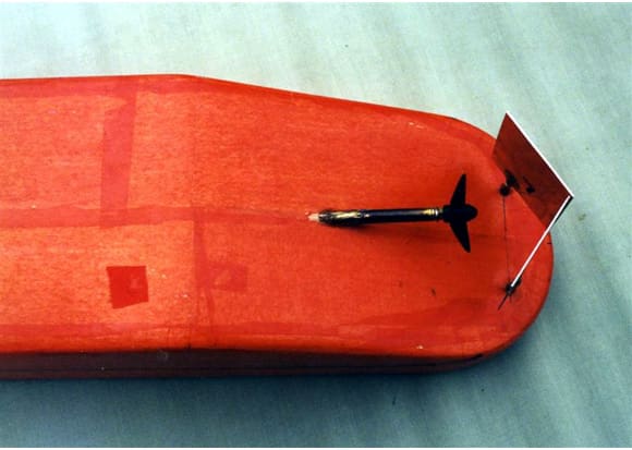
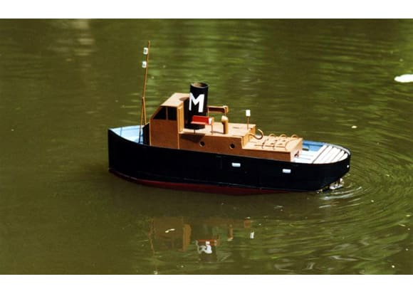
Pic 7: Parallel rudders for full ahead steaming. Pic 8: Twin servo installation for Kitchen Rudders – linkages set for ‘full ahead’. Pic 9: Parallel rudders set for a turn. Pic 10: Bringing rear edges of rudders together to slow the model. Pic 11: Rear edges of rudders together to stop model and to produce an astern movement. Pic 12: The finished model underway.
Installation
Thus encouraged a small steam powered model, based on a traditional harbour tug, was built. I decided to use my Midwest steam plant in this model as its compact form suited the hull. Previous use in the Sabina model proved that it could move this size of hull at a realistic speed.
This steam plant seems to give its best performance turning a 45mm diameter two bladed plastic propeller. After some experimentation, and a lot of head scratching I add, the best layout appeared to be with the rudder blades mounted some 65mm (2.5 inches) apart. The blade size was settled by erring on the generous, being 60mm (2.25ins) wide by 75mm (3ins) deep. The blades were cut from thin aluminium sheet and epoxied to steel shafts. The shafts were positioned to give semi-balanced rudders with about 30% of their areas ahead of the shafts.
The two servos were fitted into the hull and connected to the tiller arms with short wire links. Anticipating that lots of fine tweaking would be needed, I used adjustable servo arms and Du-Bro connectors to secure the wires to the arms. I wasn’t wrong, as it took some time to achieve reliable rudder action. At first the blades would fail to meet in the astern position, or worse jam together before the throttle stick was fully back. Adjusting the linkages to avoid these problems then resulted in the blades not being parallel when the throttle stick was fully forwards. Solving that problem resulted in limited rudder movement for steering. One persistent problem was that there was always some combination of rudder and throttle stick movement that risked a linkage going over centre and jamming. Eventually a less than perfect, but hopefully good enough mechanism was achieved.
Pond tests
At the time I was digging it! Our garden pond seemed to be another back breaking exercise I had let myself get talked into doing. Since then it has proven to be a godsend for this hobby, as new models and ideas can be tested quickly and easily. Even better, any serious fiascos are hidden from public view!
After ballasting the model, steam was raised and the model lowered into the water and the fun began. Checking the rudder actions whilst holding the model revealed no problems, everything moved as it should and nothing jammed. Releasing the model, with the throttle stick pulled full back, i.e. the rear edges of the rudders pulled together and it had no forward motion. Advancing the throttle stick, i.e. opening the gap between the rudders, resulted in the model moving ahead.
The throttle response was checked out and found to be reliable. The modest size of our pond would not let the model reach top speed, but I was pleased with the acceleration. Even better was the fact that pulling the throttle stick fully back quickly brought the model to rest. Steering, at least in the confines of the pond looked okay, but there was a problem. With the throttle stick fully back in what I hoped would be the astern mode, the model showed little desire to move backwards. At best it would drift backwards although the propeller was obviously churning around a lot of water. At least the model would stop and go reliably, so it was completed and then tested on the local canal.
Maiden Problems
Sailing on a larger water showed that the performance was good. With the throttle stick pushed fully forwards, the model had a healthy top speed of around 2 ft/sec (0.6 m/s) which looked just right for a tug of this type and size. The steering was positive and the model handled just as if it had a conventional rudder. Despite it being a windy day, the model would hold a straight course better than I expected.
Moving the throttle stick down from the fully forwards position would slow the model down. At slower speeds the steering was unaffected but, as I’d expected, the turning radius was increased. With the gap between the rudders almost closed I found an unexpected steering characteristic in that their action was reversed, that is right rudder on the transmitter caused the model to turn to the left. This caught me by surprise at first, but as the model was moving slowly it was no great challenge to adapt to this effect.
Pulling the throttle stick fully back would bring the model to stop, but as before, any astern movement was very slow. Steering astern was marginal to say the least. I did find out that it was possible to get the model to rotate by moving the rudder stick slightly whilst the throttle was fully back. This was a very handy manoeuvre whenever a model gets into a tricky situation.
Maiden solutions
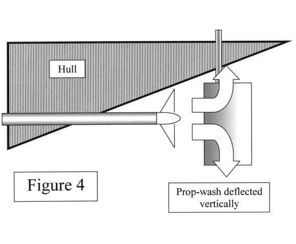
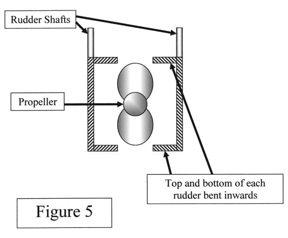
Thinking about the slow (‘hardly moving’ might be a better description) astern motion and the problem looked like it was due to the simple flat rudder blades used. When fully closed they did stop the prop-wash from moving astern, but appeared to deflect most of it up or downwards, Figure 4. The visibly turbulent water around the rudders seemed to support this idea. What was needed was to prevent the water just flowing up or down across the inner faces of the rudders and deflect it forwards. The easy answer was to bend the top and bottom edges of the rudder blades through 90 degrees to restrict this vertical motion and hopefully increase the astern force on the rudders, Figure 5.
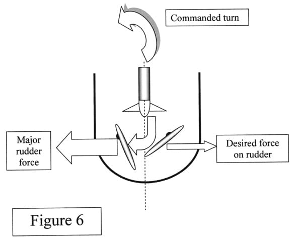
The reversed steering effect at very slow speeds looked like it was due the rudder blade on the outside of the desired turn deflecting the prop-wash on to the inner rudder and creating a larger sideways force in the wrong direction, Figure 6. No obvious way to avoid this effect could be found. In the end I settled for learning to live with it.
Sailing again
Back to the water and it looked like the bent rudders did in fact improve astern sailing. It’s still only a slow astern speed, but at least the model can be backed out of trouble. Astern steering is possible, but needed to be limited to gentle turns otherwise the model will come to rest.
The ahead sailing was unchanged and the model behaved itself, except as before at very slow speeds when the rudder action was reversed. As things are happening slowly it has never been a serious problem. Maybe it’s because my natural reaction is ‘the model is turning the wrong way, push the stick the other way’. Come to think of it, this is probably the way I sail and fly most of my models, rather than ‘It’s going to turn right even if I have to bend the rudder stick around the transmitter case’.
Judgement day!
My original objective was to achieve speed control of a model powered by a single cylinder oscillating steam engine, i.e. an engine that must run continuously in one direction. Twin parallel rudders operated in a Kitchen Rudder fashion, via a transmitter ‘elevon’ mix function have produced the desired effect. Well, I say desired effect, but must admit that it is in no way perfect. It is, however, a very simple way to control the speed of these models without incurring a lot of expense and effort. I agree we can rarely do a good job unless we know what perfection is, but we ought to be smart enough to settle for ‘good enough’.
A construction article and free plan based on the model on which this work was carried out should be published shortly. Even if you do not want to use the Kitchen Rudder idea, a single rudder behind the propeller ought to produce a nimble steam powered model, but of course speed control will be non-existent with the simple Midwest steam plant.


