R.N.L.I. and the Severn Class historyThe Royal National Lifeboat Institution has a history dating back to 1824. The lifeboats that existed in this early period were not mechanically powered craft; the only form of propulsion was by oar and sail. Brave crews would turn out in the most treacherous weather conditions and face an uphill battle that could only be won by extremely hard work, sweat and determination to save lives – even though it could have ended their life too. Up to the 19th century the idea of using steam was discussed many times, which would in principal provide many advantages over man power. However it was not until 1889 that the idea became reality with the launch of the Duke of Northumberland with a boiler that provided steam to an engine that drove hydraulic pumps, broadly equivalent to today’s water jet units. On speed trials she averaged nine knots with a potential radius of action of 250 miles. Unfortunately the disadvantages of the system outweighed the propulsion advantages, as it could take up to 30 minutes to get steam up and once under way battling the elements, she could just average five to six knots. Even keeping the boiler lit could become a major problem. Steam lifeboats lasted in service for around 30 years. The invention of the petrol engine which was doing so much for car development in the 1880’s, now found a place in the marine sector. In April 1904 there was a new period of trials, with an engine in an open lifeboat, as an auxiliary to sail. Tests were carried out which proved very promising, even to the point of placing the test vessel on station at Newhaven for six months. Although not called upon in anger, the crew were very impressed, requesting their own station lifeboat to be converted. From that moment onwards the motor lifeboat was officially born. Since that day there have been many designs of lifeboat, a trend that will no doubt continue as the quest for more speed and safety will always be the driving force. The Severn lifeboat class was introduced in 1991, based on similar lines and ideas learnt from the earlier Arun class. The new prototype name was FAB3 (Fast Afloat Boat Three). This time speed and technology would play a large part; the hull was built from (FRC) Fibre Reinforced Composite which combined strength with lightness. The deck sheer line was lowered, to reduce the freeboard to help casualty handling as on the Arun class. Internally it could carry seven crew including a doctor, plus had locations for two stretchers. All controls internally were duplicates of the flying bridge ones. A bow thruster was fitted for extra manoeuvrability, plus a Y Class inflatable boat was stored on the flying bridge deck.
Article continues below…
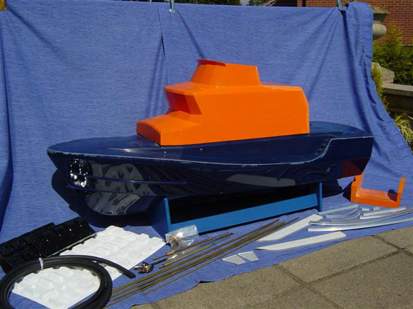
Enjoy more Model Boats Magazine reading in the monthly magazine. Click here to subscribe & save. The first batch of Severns had a Y boat that could be launched and recovered by means of a lightweight frame and winch. On later versions this was replaced with a hydraulic Hiab crane, which reduces the time and effort required for launching. The class name was chosen after the rivers that run through the heart of the country from where the R.N.L.I. receives a large amount of its income. Up until 2004, a total of 46 have been built, with a length of 17 metres, beam 5.5 metres, displacement 37.5 tonnes, fuel capacity 5,500 litres and they are fitted with twin Caterpillar 3412T engines. An excellent book by Nicholas Leach is available containing lots of information and photos, entitled RNLI Lifeboats; ISBN 1-84306-201-1, price £19.99. Speedline Models Severn Class Lifeboat SuperkitLifeboats make the most eye-catching of subjects be it full-size or a model, either because of their bright orange superstructure or the simple fact that everybody can associate with usually seeing them at the seaside. Modellers either build one or sometimes just dream of it. Now’s your chance to put that dream into reality. For sometime Adrian Gosling of Speedline Models had been designing with the aid of his team, a 1:12 scale superkit of the Severn Class, the R.N.L.I.’s largest in it’s fleet, to compliment his existing Trent class kit – and this is now a reality. The model kit is based around two very strong high quality GRP mouldings of the hull, including a pre-fitted deck, plus the superstructure. The model has an overall length of 58ins by 18ins beam. This kit in the hands of a good modeller makes into a top quality museum standard model that the builder will be proud of. It can be purchased as a complete kit of parts, or as individual sets (listed at the end), thus spreading the cost as the build progresses. This method of building is well suited to scratch builders who wish to build some parts themselves. Whichever method is chosen, the sets making up the full kit are as follows: hull and wheelhouse GRP mouldings set; detail sets in laser-cut Perspex and etched brass; resin and pewter casting set; handrails/stanchion and kicking board set; running gear set; window set; vac-forming set; screw set; rubber fendering pack; miscellaneous collection of annealed brass rod to make up all grab rails, mast, etc. and the Y boat. Instructions along with a comprehensive picture CD of a real Severn lifeboat complete the package. There are no plans supplied for copyright reasons. These have to be obtained direct from the R.N.L.I. at around £18 for a set of three. The price for all this is around £950, a high price you may think, but on closer inspection it is very realistic for the super high quality parts that you get and no hull or superstructure to build either. It’s a big model that’s extra big on detail and is well suited to a river or large lake for operating. See Photos 1 to 3. |
|
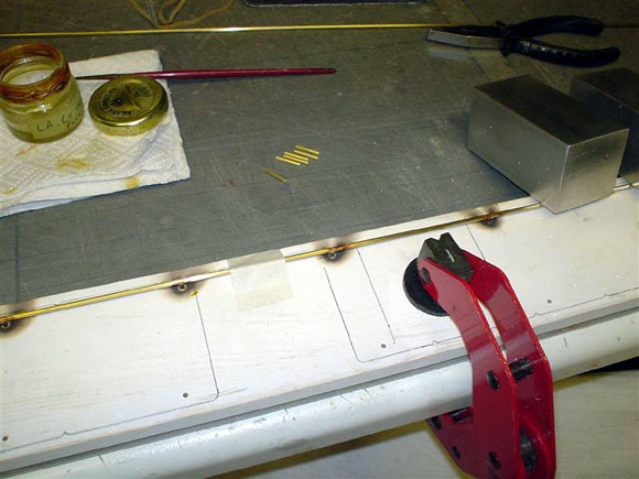
The BuildWith a large project like this it takes time and although a lot of the hard bulky work has been done for you with the GRP mouldings there is still plenty to do. I hope to explain the majority of the build and techniques used and where there are gaps the photos should tell the story. It’s been a long build, but an extremely enjoyable one and once completed and on the water it was all very much worth it. DrawingsSpeedline do not supply any drawings but they do supply a photo CD containing many pictures showing close up detail and overall shots of a real Severn class lifeboat. So a plan needs to be sourced which is a very simple task by contacting the R.N.L.I. at West Quay Road, Poole, Dorset, BH15 1HZ or Tel: 01202 663276. The contact at the time of writing was a Mrs. J Durman who is the Engineering Secretary, email [email protected]. The plan set comes as three A1 size sheets, although in actual fact only one sheet is required, this being the general arrangement drawing which has been drawn at 1:20 scale. This is no great problem, as Speedline have indicated that all dimensions need to be multiplied from the plan by 1.66. One can either do this as you go along, or go through the plan marking up all relevant dimensions in red, which for me was the best method and much quicker in the long run. Also you start to get an appreciation where everything goes and what it is. The plans together with the photos are your bible so to speak. Brasswork notesA lot of this kit is made up of etched brass, rod and tube that will ideally require good soldering skills, either with the use of silver solder or soft solder. Instead of repeating myself every time through this review, here is my method of soldering. I have spent some years, due to my electronics background, perfecting my methods of soldering, especially using soft solder and as for some reason I never felt very comfortable with silver solder, everything I do will be using the former. I also use just one type of solder and all my models use the same method of soldering and with the big Severn there is plenty of it, believe me! There is no easy way of getting around it so just enjoy! Some think it’s a black art which it is not – just good tools, the right heat, a good quality flux and solder, as well as a steady hand. The saying ‘practice makes perfect’ is very true with this skill. For small work I use a mains powered adjustable temperature soldering iron of up to 60 watts, as used in electronics work and is ideal for small delicate items and medium jobs. For the larger jobs I use a Butane gas torch. This is compact and sturdy, the flame is fully adjustable in length and intensity capable of producing a maximum temperature of 1,300 degrees C. The solder is of the standard electronic type, resin cored 60% tin 40% lead, 22SWG. As for the flux, well if you want a super clean good flowing solder joint I would highly recommend the use of LA-CO Brite regular soldering flux which is a non acid and non toxic flux. In the past I have used Carr’s flux which is corrosive and therefore also requires the parts to be cleaned, ideally immediately after the process. The best surface to solder on is a mat made from a non-burning material. At a recent model show I purchased a Skamolex plate, which is very light in weight and looks like very tightly compressed cork. It does not burn and it insulates, but does not draw the heat away from the item being worked on. The other big bonus is that it is asbestos free. Mine is mounted within a wooden frame for protection, as the plate is quite flexible and will break easily. For holding the material during the solder process I use either crocodile clips as used in electronic work, or aluminium hair clips (the latter can be bent to any shape to hold the work and they can also be used as a way of taking the heat away from an adjacent joint. The other items I use a lot of, are various sizes of metal and aluminium blocks. When it comes to bending brass I always use the best tools available – bending tools such as springs, various shaped pliers, jigs and formers work a treat. How to solder a joint is knowing where to place the heat, the correct amount of heat, how long for and when to remove the heat. The thing to remember is the flux is there to help the solder flow and it does not need a great deal of heat, nor does the solder and they should not be applied at the same time in the flame. Brass needs to have a little flux applied to the two surfaces before heat is applied and soldered. I then heat up both surfaces which require joining together at the same time with the flame or heat source – the flux will start to flow a few seconds later. Just as the brass starts to go from a semi bright colour to a dull colour, I remove the heat and apply a little solder – not too much – just enough to flow and create the joint and then leave to cool. Once cool the joint should be shiny silver. If it is dull then that is what we call a dry joint and it will most likely break if put under pressure. Gravity plays a big part, so all pieces need to be kept level. There is no point soldering anything on a downward slant as the molten solder would just run down away from the joint. Soldering multiple joints near to each other can be made easier with the use of aluminium hair clips or blocks depending on location – either to hold or act as a heat shunt – thus avoiding other nearby joints coming melting. Of course there are other methods, one being the use of different melting temperature solders. My method works very well for me and I think it is much easier and less fiddly. When heating up flat thin brass, care has to be taken not to use too much heat, otherwise you can distort the brass. Once all the soldered joints have cooled down I give them a wipe over with white spirit to remove any flux residue, then wash them with mild soapy water and clean up with a fine wire brush and wet and dry abrasive paper ready for painting. Photos 4 and 5 show the tools involved plus finished soldered parts. Etched Brass and Perspex SheetThe quality of all these sheets with all the holes, cut outs and the fine etched detail is first class. Any areas requiring folding or gluing should be done on a flat surface. For Perspex I used a thick sheet of glass as it is a perfectly flat surface to work on. A good sign of quality etching or laser cutting are straight and clean edges which is very much the case here. Both materials are superb for spray painting and machining. The preparation for painting and gluing the surface areas simply just requires a light sanding down with very fine wet and dry abrasive paper; 400 – 1000 grade works for me. To glue the relevant brass etch to Perspex or GRP I have used liquid superglue, just enough and not too much so that it does not run otherwise as you press the plate firmly into position all the glue will ooze out. I also found that once the superglue is applied to the brass surface alone, it starts to set very quickly, so speed and accuracy all at the same time is required. So once offered up to its mating surface you really only have one go at it – once in close contact it’s set. Any areas requiring a part to be soldered to it should be done off the model first. I always try to think a few steps ahead, especially when it comes to painting. Should a part be on the model now or later? Even depending on what colour the part needs to be can be a deciding factor. Please note that when positioning and gluing on the lower side vent brass plate overlays, that they should overhang the hull sides slightly around 3mm lower than the wheelhouse. Also care should be taken when removing Perspex detailed parts from their mother sheet as double-sided tape is used to hold them securely in place during the laser cutting process and it is very strong I can assure you. See Photos 6 to 7. |
|
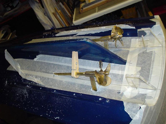
ScratchbuiltIt has to be said that although this is a kit containing many parts and fittings, there are a few items the modeller will have to make from scratch or source themselves. On closer inspection of the photo CD and plan these become more apparent. If you decide to base the model on one of the actual stationed lifeboats, then there is a very good chance other differences will emerge. This is because each coxswain can request changes to a standard ex-factory craft, as different seas, areas and local requirements can dictate these alterations. I have noticed that some parts fitted to the lifeboats differ as they may come from various manufacturers and builders – even the orange and blue paint varies slightly, so do your homework! The parts that do require making up have been simple and easy to do. In fact if you can build the kit then the rest is simple. HullThe hull comes as a very substantially laid up GRP moulding, with the deck already moulded on and if you are used to the average size car boot type model, then this 1:12 scale big Severn (and I do mean big) takes on a whole new dimension. Even the first job of deciding materials and marking out to build a suitable building/docking stand for it to sit on requires some forward planning, allowing for the skegs and shafts. Thinking, solving, planning and then building is all part of the interest. The best way I found to find the hull shape to build a suitable stand was by using a profile gauge, although this time due to the size of the gauge being only 10ins long, it could only be done in stages. Working from the keel outwards to find its true profile was the best way, then I transferred the shapes on to a piece of cardboard and a trial template can be made and checked for correct fit based on its position on the hull. Forward thinking for the stern part of the stand’s shape is required along with the depth of the skegs and propeller shaft ‘A’ frame locations, so that allowances can be made. The choice of materials for the stand needed to be strong, so I have chosen to use 18mm thick multi layer resin bonded marine plywood as I had some to hand. The cross braces are 50mm x 25mm painted softwood and the protective rubber edge is cut from an old computer mouse mat, glued on with Evostik to each stand face to protect the hull. Motor and Gearbox SetDeciding on what motors to use is not always an easy task and with a larger model this can be even more difficult. Luckily Speedline have carried out some tests and their recommendation of power plant seemed the only good choice, which is what I have used by sourcing the parts required from MFA, (see parts list below). Each main prop shaft is connected to two drive motors by means of pulleys, shafts and a toothed belt. Also, to aid smooth running, bearing blocks have been fitted, all obtained from the same supplier. Motor and Pulley parts list: 4 x Torpedo 850 Motors and Mounts – Pt. No.966D2.11. The first job is to mount all the motors on their respected motor mounts. Next task was to purchase a sheet of 4mm thick aluminium plate, large enough to make two main base plates for port and starboard drive assemblies. During the marking out stage of each base plate, I had to allow for belt tensioning. This was achieved by filing the four base plate holes for each outer motor as slots. Once fitted I would then be able to slide the motor and its mount up to 7mm between the two widest centre pulleys enabling tensioning of the belt. I have set the belt tension not too tight or too loose, with approximately 3mm of up and down movement. The inner motor and lower bearing blocks are permanently bolted in position. Each motor is then fitted with noise suppressor capacitors across the terminal connection points and one to the metal case. Once all assembled and tensioned I did some power consumption tests out of the water and off load with a 12v battery connected across both motors in parallel. Using a digital multimeter set to amps in line with the positive wire (one drive assembly), it drew 9.2amps and I guessed that once in the boat and on the water it would go up to around 13amps – maybe 15amps at full speed. See Photos 8 to 12. |
|
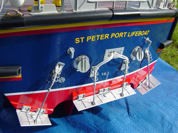
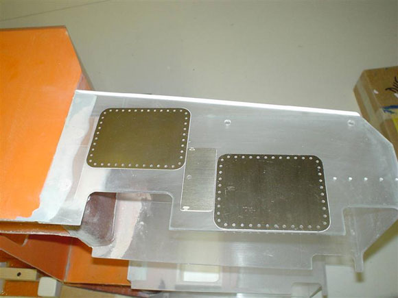
Bilge KeelsThese are made up from two 5mm thick laser cut Perspex parts which for strength purposes needs to have some brass pins/rods inserted inside that would then pass through the hull into the interior for added strength. I have done this by drilling seven holes 30mm deep with the use of a vertical pillar drill, Photo 13, equally spaced along the upper edge of each keel, then 60mm lengths of 3mm brass rod were glued in place with Superglue in each hole. I then offered the keel up to its final location, marked the positions of each rod on to the hull, then drilled the holes through. I spread a thin layer of P38 car body filler onto each joining surface and pushed the keel home, wiping away any excess filler. I carefully lined up both keels so that when the deck is level, the keels are vertical. Allow the filler to set hard. On the inside I have fitted a length of square wood with the same spaced holes drilled through and placed over the brass rod/pins for extra upright strength – all held in place with P38 filler. Once fully cured, all can then be sanded to blend in. Running GearThe shafts and props come supplied and are of a very high quality. The parts to make up the two ‘A’ frames come as flat brass and two short round pieces of brass bar with the centre hole drilled out ready to accept the diameter of the shaft tube. The ‘A’ frame brass flat side supports need to be cut and shaped as they are both to become angled handed pairs. The location dimensions are as per the plan. Speedline have now updated this item as part of their continued programme to keep up with new ideas and technology, also making them more scale like, so they are now cast in engineer’s resin with piano wire inside for added extra strength. They are fitted with two bronze bushes giving four bearings per shaft. On my model the standard long propeller shafts are used. For all to fit correctly and with correct alignment, the measurements and location of each ‘A’ frame and shaft were marked out evenly on both sides between the tunnels, then the holes were drilled and slots filed. Before fixing all in position, the best way to line up everything is with both motor drive assemblies mounted on wood block mounts, and placed in position for dry fitting tests to make sure everything lines up perfectly. Once happy all can be permanently fixed in place. The rudders and posts are made up from the pre-cut Perspex blades sanded to shape. The posts are 3mm diameter brass rod. Each blade requires a 3mm diameter hole to take the brass rudder post. Drilling a hole perfectly upright at 90 degrees down the centre of a piece of 5mm thick Perspex is not an easy task and the use of a pillar drill is essential. Now there is no point in just inserting the rod down into the hole with a little glue and thinking it will rotate the rudder forever, because it won’t! It’s bound to come loose so there needs to be some form of grip or cross piece holding the blade on to the post to absorb some of the forces during manoeuvres, so once again the pillar drill is required to provide another hole. This one is 2mm diameter through the centre width of the Perspex blade and a length of 2mm diameter brass rod can be inserted, glued and capped off with filler. The rudder post sleeves are simply from brass tube. Once the rudder location holes are in place, it was a case of dry assembling everything, making sure all visible angles are the same, plus the distance of propellers to rudder blades and with the rudders upright before fixing in place. See Photos 14 to 17. Bow Thruster and BulgeFitting a bow thruster is never an easy task. It’s a bit more than just drilling a round hole and fitting a tube, especially as the hole shape is actually oval on both sides of the hull because of the angles and the thruster must be in positioned symmetrically. The first job is to work out from the plan and supplied photo CD its actual location on the hull. As always, all marking out is done on an overlay of masking tape. The only large commercial bow thruster available is the Robbe No.1155 which is actually on the small side regards diameter, but it could be used. My choice, as I had one, was an early Robbe production unit part No.1486, unfortunately no longer readily available. It has an inner diameter of 32mm and with two propellers I was hoping it would do the job. I decided the supplied 380 size motor would not be powerful enough, so I replaced it with a 545 type. Once the correct shaped holes were marked out, it was a case of drilling a series of holes inside the desired shape to remove the excess material and then filing to shape until the bow thruster tube was a snug fit. The tube was then roughened up all over on the outside with coarse glasspaper, inserted and held in position with a couple of spots of 5-min epoxy glue, making sure that the motor access holes were pointing upwards. Once all looked correct I then later strengthened up the joints with P38 car body filler. The length of this tube is dictated by the width and shape of the hull which on further inspection of photos of a real Severn, showed a very distinctive bulge around the opening on both sides, and then it tapers away. Now there were two ways I could emulate this, either by shaping appropriately thick styrene plastic or ply, then gluing in position and coating all over with P38 filler and sanding to shape – or leaving approximately 13mm of the bow thruster tube hanging out all round on both sides of the hull and building up the bulge with the P38. I roughened up the outside of the hull roughly where the bulge is positioned with coarse sandpaper for the filler to key to, then applied the filler in three layers to the shape of the bulge and allowed it to cure well and then sanded it to final shape. Humbrol Fine Model Filler was used as and when necessary to achieve a smoother finish. It took lots of sanding and tons of dust, but well worth the effort to reproduce. See Photos 18 to 20. Transom and Trim TabsThe flat transom has quite a bit of detail to be added from the etched brass and cast resin set. The first job is to locate all the parts, that way one can work out the dimensions of any cut outs required. The transom was covered all over with masking tape to allow for easier marking out. Once the centre line and waterline position was drawn in, then from the plan and photos I could work out the position of each component, including any holes to be drilled. The trim tabs and associated parts are all soldered together and can be very fiddly to complete. |
|
Heat shunts have been used to stop other already soldered parts coming off, and etched parts with holes need to be lined up and double checked for their correct position before final soldering and eventually connecting them to their respective hydraulic rams. The latter are made up from 5/32in brass tube with brass rod from the K&S range of materials, the rod fitting inside the tube and drilled through at the connecting ends. Now for the more adventurous modellers these trim tabs could actually be made to work via cables or wires, but I felt quite happy to have them fixed at a slight angle which in turn would make the bow stay down slightly at speed. Phil Locke, who has been documenting his build of the Speedline Severn on his website, has worked this out to be about five degrees, so that’s how I have set mine. I must say his website is a must to visit, www.philsrcmodels.co.uk. He has many more lifeboats in the making so keep looking. Before mounting the trim tabs on the stern there are three resin blocks to glue in position with superglue, then the trim tab hinges are fixed in place by pinning with brass pins all the way through to the inside and bending over the pin to give a stronger and more secure fit. Once all is in place and bent over, a layer of P38 is placed over them all inside to seal and hold fast. The hinge part of the tabs is just a length of brass rod. I have simulated the hydraulic pipes with the use of plastic tube cut and bent to shape. This came from a children’s craft idea called Scooby Doos! All colours and sizes can be found, making them useful for all sorts of things. On each tab there is a half round dome shape with a wire connected to it. These are called anodes and I have reproduced them by placing a length of 10mm diameter plastic rod in my lathe and filing over the end to get the dome shape, then cutting off at the correct depth, drilling a small hole top centre and gluing in a piece of wire. Simple and effective, times it by three and another job is done! See Photos 21 to 33. Kicking BoardsThese are made from ‘T’ section aluminium extrusion, all pre-shaped by Speedline. To achieve some of the required bends, some filing, grinding and bending takes place on the extrusion which is the raw state you receive them. So to tidy it all up, especially the vertical surfaces, some filling with Humbrol Model Filler was required, plus a little final shaping and sanding. To be fair it is a much simpler job to do this than try and bend ‘T’ sectioned aluminium yourself, so well done Speedline. The cutting to length and position of each one is obtained from the plan, not forgetting the multiplication factor. These can then be glued to the deck with epoxy glue or superglue gel. I have also chosen to pin them down to the deck using round head brass veneer pins – this is my usual method of pinning things. Holes were drilled through the ‘T’ section and deck and little gel superglue applied between the ‘T’ section and deck, plus pins inserted and bent over on the underside as extra support. Once happy, all the kicking boards were then painted using Humbrol Medium Satin Grey No.165, although on hindsight I should have sprayed these off the model and then fitted them later for ease and a better paint line. See Photos 34 to 37. Textured DeckThe deck being already moulded on to the hull cuts down the workload considerably. Some cutting out and trimming is required at the hull opening sides for the superstructure to fit neatly once the valve boxes have been fitted to the wheelhouse. To obtain a smoother fitting of the superstructure I have sanded a chamfer with the use of Proxxon’s handy new Block Belt Sander BBS/S, a power tool well worth having and which made very short work of it, but care has to be taken not to overdo sanding at the sides. The deck finish on all lifeboats is anti-slip for a better grip under foot. There are a number of ways to achieve this. One is to use thick paint semi-dry and a stiff flat brush in a stippling motion to create raised bumps. Another way is by using textured coatings as used on car bumpers, available in a spray can by Rust-oleum No.2486 500ml size. Don’t forget to mask off the necessary areas. Another way I have seen some modellers achieve this, is by cutting and gluing on sheets of fine black wet and dry abrasive paper at a grit rating which can give a very good effect – except for all the join lines. My chosen method is to use fine oxide abrasive powder from good airbrush centres or Squires Tools. This is then mixed in with the right colour paint for the deck – in this case I have used Humbrol Grey No.27 mixed with a little standard Light Grey No.147 just to lift the darkness a little, applied with a 20mm wide flat brush. The trick is to keep mixing the powder within the paint as you progress so that it does not settle to the bottom. Three coats were applied which gave the correct textured finish. Finish off with a final thin coat of paint, but not too much to lose the anti-slip effect. See Photos 38 to 39. PAGE 2 |
Severn Class
by
–
Advert
Enjoy more Model Boats Magazine reading every month. Click here to subscribe.
Article Tags:


